VAT 650 Series Installation, Operating, & Maintenance Instructions
Pendulum control & isolation valve with logic interface
Hide thumbs
Also See for 650 Series:
Table of Contents
Advertisement
Quick Links
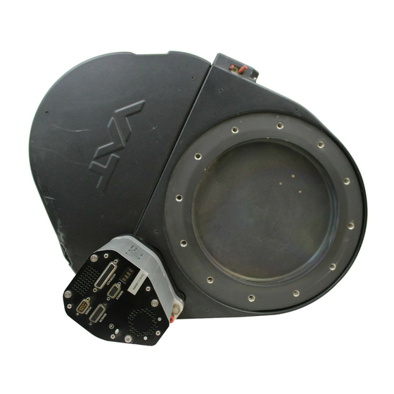
Pendulum control & isolation valve
with Logic interface
This manual is valid for the valve ordering number(s):
650 . . - . . GC - . . . .
650 . . - . . GE - . . . .
650 . . - . . AC - . . . .
650 . . - . . AE - . . . .
650 . . - . . HC - . . . .
650 . . - . . HE - . . . .
650 . . - . . CC - . . . .
650 . . - . . CE - . . . .
SPS = Sensor Power Supply
configured with firmware
The fabrication number is indicated on each product as per the label
below (or similar):
made in Switzerland
Fabrication No.:
patented
650 . . – . . . . – . . . . / . . . .
A – . . . . . .
Explanation of symbols:
Read declaration carefully before you start any other
action!
Attention!
Product is in conformity with EC guidelines,
if applicable!
Disconnect electrical power and compressed air
lines. Do not touch parts under voltage!
Read these «Installation, Operating & Maintenance Instructions» and the enclosed «General
Safety Instructions» carefully before you start any other action!
VAT Vakuumventile AG, CH-9469 Haag, Switzerland
Tel +41 81 771 61 61 Fax +41 81 771 48 30 CH@vatvalve.com www.vatvalve.com
Installation, Operating & Maintenance Instructions
Series 650 DN 320-400 (I.D. 12" - 16"), Logic
(1 sensor input)
(2 sensor inputs)
(1 sensor input / ±15V SPS)
(2 sensor inputs / ±15V SPS)
(1 sensor input / PFO)
(2 sensor inputs / PFO)
(1 sensor input / ±15V SPS / PFO)
(2 sensor inputs / ±15V SPS / PFO)
PFO = Power Failure Option
650P.1E.05, 650P.1E.32, 650P.1E.36
. .
Fabrication number
sample picture
Keep body parts and objects away from the valve
opening!
Hot surfaces; do not touch!
Loaded springs and/or air cushions are potential
hazards!
Wear gloves!
267422EC
2009-11-30
1/56
Advertisement
Table of Contents

Related Manuals for VAT 650 Series


Summary of Contents for VAT 650 Series
- Page 1 Do not touch parts under voltage! Read these «Installation, Operating & Maintenance Instructions» and the enclosed «General Safety Instructions» carefully before you start any other action! VAT Vakuumventile AG, CH-9469 Haag, Switzerland 267422EC 1/56 Tel +41 81 771 61 61 Fax +41 81 771 48 30 CH@vatvalve.com www.vatvalve.com...
- Page 2 VAT products. The VAT firmware contains a limited, time unlimited user license. The VAT firmware may not be used for purposes other than those intended nor is it permitted to make copies of the VAT firmware. In particular, it is strictly forbidden to give copies of the VAT firmware to other people.
-
Page 3: Table Of Contents
Valve unit ............................... 53 Accessories ..............................54 7.3.1 Centering ring with Viton o-ring ......................55 8 Warranty ................................. 56 VAT Vakuumventile AG, CH-9469 Haag, Switzerland 267422EC 3/56 Tel +41 81 771 61 61 Fax +41 81 771 48 30 CH@vatvalve.com www.vatvalve.com 2009-11-30... -
Page 4: Use Of Product
This product is a throttling pendulum valve with isolation functionality. It is intended to use for downstream pressure control applications. Use product for clean and dry indoor vacuum applications under the conditions indicated in chapter «Technical data» only! Other applications are only allowed with the written permission of VAT. Technical data Control and actuating unit +24 VDC (±10%) @ 0.5 V pk-pk max. - Page 5 Refer to chapter «Sensor supply concepts» for details. Refer to chapter «Schematics» for details. PFO = Power Failure Option. Refer to «Behavior in case of power failure» for details. VAT Vakuumventile AG, CH-9469 Haag, Switzerland 267422EC 5/56 Tel +41 81 771 61 61 Fax +41 81 771 48 30 CH@vatvalve.com www.vatvalve.com...
- Page 6 30 l/s molecular flow) Dimensions Refer to dimensional drawing of specific valve ordering number (available on request) VAT Vakuumventile AG, CH-9469 Haag, Switzerland 267422EC 6/56 Tel +41 81 771 61 61 Fax +41 81 771 48 30 CH@vatvalve.com www.vatvalve.com 2009-11-30...
-
Page 7: Installation
Do not disconnect air supply when device is under power. Compressed air pressure must be in the range of: 4 - 7 bar / 55 - 100 psi (above ATM). Use only clean, dry or slightly oiled air. VAT Vakuumventile AG, CH-9469 Haag, Switzerland 267422EC 7/56 Tel +41 81 771 61 61 Fax +41 81 771 48 30 CH@vatvalve.com www.vatvalve.com... - Page 8 This valve has a double sealed rotary feedthrough and optionally an intermediate pumping port for the actuator shaft. This port (1/8“ ISO/NPT) could be connected to the vacuum line, see Figure 2 below. This valve may optionally be equipped with a heating device. Connect VAT heating device according to manual of respective heating device.
-
Page 9: Tightening Torque
0.79 (65052 - ..- ..) Refer to «Spare parts and accessories» for centering rings ordering numbers. VAT Vakuumventile AG, CH-9469 Haag, Switzerland 267422EC 9/56 Tel +41 81 771 61 61 Fax +41 81 771 48 30 CH@vatvalve.com www.vatvalve.com... -
Page 10: Mounting With O-Ring In Grooves
For a combination of both forces (F and M) the values are invalid. Verify that the depth of the mounting screws is min. 1 x thread diameter. Please contact VAT for more information. VAT Vakuumventile AG, CH-9469 Haag, Switzerland 267422EC 10/56 Tel +41 81 771 61 61 Fax +41 81 771 48 30 CH@vatvalve.com www.vatvalve.com... -
Page 11: Requirements To Sensor Connection
650 . . - . . A . - ../ 650 . . - . . C . - ..SPS module included Note: The SPS module can be retrofitted. Refer to chapter «Retrofit / replacement procedure» for instruction. VAT Vakuumventile AG, CH-9469 Haag, Switzerland 267422EC 11/56 Tel +41 81 771 61 61 Fax +41 81 771 48 30 CH@vatvalve.com www.vatvalve.com... -
Page 12: Power And Sensor Connection (+24 Vdc Sensors)
Do not connect other pins, that may damage power supply or controller! • Connector: Use only screws with 4-40UNC thread for fastening the connectors! VAT Vakuumventile AG, CH-9469 Haag, Switzerland 267422EC 12/56 Tel +41 81 771 61 61 Fax +41 81 771 48 30 CH@vatvalve.com www.vatvalve.com... - Page 13 • Connector: Use only screws with 4-40UNC thread for fastening the connectors! VAT Vakuumventile AG, CH-9469 Haag, Switzerland 267422EC 13/56 Tel +41 81 771 61 61 Fax +41 81 771 48 30 CH@vatvalve.com www.vatvalve.com...
-
Page 14: Power And Sensor Connection (±15 Vdc Sensors) Without Optional Sps Module
Do not connect other pins, that may damage power supply or controller! • Connector: Use only screws with 4-40UNC thread for fastening the connectors! VAT Vakuumventile AG, CH-9469 Haag, Switzerland 267422EC 14/56 Tel +41 81 771 61 61 Fax +41 81 771 48 30 CH@vatvalve.com www.vatvalve.com... - Page 15 • Connector: Use only screws with 4-40UNC thread for fastening the connectors! VAT Vakuumventile AG, CH-9469 Haag, Switzerland 267422EC 15/56 Tel +41 81 771 61 61 Fax +41 81 771 48 30 CH@vatvalve.com www.vatvalve.com...
-
Page 16: Power And Sensor Connection (±15 Vdc Sensors) With Optional Sps Module
Do not connect other pins, that may damage power supply or controller! • Connector: Use only screws with 4-40UNC thread for fastening the connectors! VAT Vakuumventile AG, CH-9469 Haag, Switzerland 267422EC 16/56 Tel +41 81 771 61 61 Fax +41 81 771 48 30 CH@vatvalve.com www.vatvalve.com... -
Page 17: Logic Interface Connection
The service port (connector: SERVICE) allows to connect the valve to a RS232 port of a computer. This requires a service cable and software from VAT. You can either use our freeware 'Control View', which can be downloaded from www.vatvalve.com or purchase our 'Control Performance Analyzer'. -
Page 18: Operation
Local operation means that the valve is operated via the service port using a computer or the Service Box 2. When using a computer, a service cable and a software from VAT are required. You can either download our freeware 'Control View' from or purchase our 'Control Performance Analyzer'. -
Page 19: Remote Operation
Valve position after power up is closed Valve position after power up is open Refer also to chapter «Display information». VAT Vakuumventile AG, CH-9469 Haag, Switzerland 267422EC 19/56 Tel +41 81 771 61 61 Fax +41 81 771 48 30 CH@vatvalve.com www.vatvalve.com... -
Page 20: Behavior In Case Of Power Failure
Display indicates F. position pendulum plate at the current position. *) Provided that battery pack of the VAT controller is charged. Charging time after power up is 2 minutes max.. All parameters are stored in a power fail save memory. Display information There is a 4 digit display located on the panel. - Page 21 Power failure Service request If SR is blinking alternatively with the actual mode display (e.g. P.11 ⇔ ..SR) the valve requires cleaning. VAT Vakuumventile AG, CH-9469 Haag, Switzerland 267422EC 21/56 Tel +41 81 771 61 61 Fax +41 81 771 48 30 CH@vatvalve.com www.vatvalve.com...
-
Page 22: Setup Procedure
Note: It’s not possible to do ‘Interface configuration‘ Do configuration in menu ‘Setup / Interface’. via remote operation. VAT Vakuumventile AG, CH-9469 Haag, Switzerland 267422EC 22/56 Tel +41 81 771 61 61 Fax +41 81 771 48 30 CH@vatvalve.com www.vatvalve.com... -
Page 23: Valve And Sensor Configuration
Note: Do not perform ZERO, if the base pressure of your vacuum system is higher than 1‰ of sensor full scale. We recommend disabling ZERO function in this case; refer to «Valve configuration» of the setup procedure. Otherwise incorrect pressure reading is the result. VAT Vakuumventile AG, CH-9469 Haag, Switzerland 267422EC 23/56 Tel +41 81 771 61 61 Fax +41 81 771 48 30 CH@vatvalve.com www.vatvalve.com... -
Page 24: Learn
Note: Learn may take several minutes. Do not interrupt the routine as a single full run is required to ensure fast and accurate pressure control. The PID controller covers 5% to 5000% of the gas flow which was used for learn. VAT Vakuumventile AG, CH-9469 Haag, Switzerland 267422EC 24/56 Tel +41 81 771 61 61 Fax +41 81 771 48 30 CH@vatvalve.com www.vatvalve.com... -
Page 25: Close Valve
Select or enter position setpoint Set position SETPOINT Note: In case CLOSE VALVE, OPEN VALVE or HOLD is also set these have higher priority. VAT Vakuumventile AG, CH-9469 Haag, Switzerland 267422EC 25/56 Tel +41 81 771 61 61 Fax +41 81 771 48 30 CH@vatvalve.com www.vatvalve.com... -
Page 26: Pressure Control
For monitoring purpose each sensor signal may be read out individually. Note: Make sure that both sensors are calibrated. Note: Do not close optional gauge isolation valves during the transition phase between the sensors. VAT Vakuumventile AG, CH-9469 Haag, Switzerland 267422EC 26/56 Tel +41 81 771 61 61 Fax +41 81 771 48 30 CH@vatvalve.com www.vatvalve.com... - Page 27 Above picture shows a 2 sensor system. In this configuration sensor 2 covers low range (100 mTorr) and sensor 1 covers high range (1 Torr). Switchover between sensors is done automatically according to «Pressure control operation with 2 sensors». VAT Vakuumventile AG, CH-9469 Haag, Switzerland 267422EC 27/56 Tel +41 81 771 61 61 Fax +41 81 771 48 30 CH@vatvalve.com www.vatvalve.com...
-
Page 28: Tuning Of Control Performance
Pumping speed (l/s) and pump type (e.g. turbo pump) • System description • Problem description Send diagnostic file with and all required information to tuning-support@vat.ch VAT Vakuumventile AG, CH-9469 Haag, Switzerland 267422EC 28/56 Tel +41 81 771 61 61 Fax +41 81 771 48 30 CH@vatvalve.com www.vatvalve.com 2009-11-30... - Page 29 Note: It’s not possible to do ‘Interface configuration‘ Do configuration in menu ‘Setup / Control Parameter’. via remote operation. VAT Vakuumventile AG, CH-9469 Haag, Switzerland 267422EC 29/56 Tel +41 81 771 61 61 Fax +41 81 771 48 30 CH@vatvalve.com www.vatvalve.com...
- Page 30 Note: It’s not possible to do ‘Interface configuration‘ Do configuration in menu ‘Setup / Control Parameter’. via remote operation. VAT Vakuumventile AG, CH-9469 Haag, Switzerland 267422EC 30/56 Tel +41 81 771 61 61 Fax +41 81 771 48 30 CH@vatvalve.com www.vatvalve.com...
-
Page 31: Logic Interface
3.11 Logic interface Default configuration: OPEN input CLOSE input OPEN output CLOSE output not inverted not inverted open close VAT Vakuumventile AG, CH-9469 Haag, Switzerland 267422EC 31/56 Tel +41 81 771 61 61 Fax +41 81 771 48 30 CH@vatvalve.com www.vatvalve.com 2009-11-30... -
Page 32: Functions And Wiring
Configuration with switches for digital inputs: Note: Use a shielded cable for analog inputs. Do not connect other pins than indicated above! Connector: Use only screws with 4-40UNC thread for fastening the DB-25 connector! VAT Vakuumventile AG, CH-9469 Haag, Switzerland 267422EC 32/56 Tel +41 81 771 61 61 Fax +41 81 771 48 30 CH@vatvalve.com www.vatvalve.com... - Page 33 Configuration with voltage source for digital inputs: Note: Use a shielded cable for analog inputs. Do not connect other pins than indicated above! Connector: Use only screws with 4-40UNC thread for fastening the DB-25 connector! VAT Vakuumventile AG, CH-9469 Haag, Switzerland 267422EC 33/56 Tel +41 81 771 61 61 Fax +41 81 771 48 30 CH@vatvalve.com www.vatvalve.com...
-
Page 34: Digital Inputs
50ms to be effective. Refer to «Function and wiring» for details about input circuit. Highest priority is 1. Functions with lower priorities will not be effective as long as higher priority functions are active. VAT Vakuumventile AG, CH-9469 Haag, Switzerland 267422EC 34/56 Tel +41 81 771 61 61 Fax +41 81 771 48 30 CH@vatvalve.com www.vatvalve.com... - Page 35 50ms to be effective. Refer to «Function and wiring» for details about input circuit. Highest priority is 1. Functions with lower priorities will not be effective as long as higher priority functions are active. VAT Vakuumventile AG, CH-9469 Haag, Switzerland 267422EC 35/56 Tel +41 81 771 61 61 Fax +41 81 771 48 30 CH@vatvalve.com www.vatvalve.com...
-
Page 36: Digital Outputs
COMMON Common for all digital outputs. common Refer to «Function and wiring» for details about output circuit. VAT Vakuumventile AG, CH-9469 Haag, Switzerland 267422EC 36/56 Tel +41 81 771 61 61 Fax +41 81 771 48 30 CH@vatvalve.com www.vatvalve.com 2009-11-30... -
Page 37: Analog Inputs And Outputs
Chassis ground connected to case. Shall be used to connect cable shield. ground Refer to «Function and wiring» for details about input / output circuit. VAT Vakuumventile AG, CH-9469 Haag, Switzerland 267422EC 37/56 Tel +41 81 771 61 61 Fax +41 81 771 48 30 CH@vatvalve.com www.vatvalve.com... -
Page 38: Trouble Shooting
Exhaust «AIRx» compressed air input and output - Contact your local VAT service centre for support. - No compressed air at output exhaust 1)Priority of pin 14 is higher than pin 13. If pin 14 is connected to ground after pin 13 the valve will close. - Page 39 - Make sure a shielded sensor cable is used. If you need any further information, please contact one of our service centers. You can find the addresses on our website: http://www.vat.ch VAT Vakuumventile AG, CH-9469 Haag, Switzerland 267422EC 39/56 Tel +41 81 771 61 61 Fax +41 81 771 48 30 CH@vatvalve.com www.vatvalve.com...
-
Page 40: Maintenance & Repairs
Contamination from the process may influence the function and requires more frequent maintenance. Before carrying out any maintenance or repairs, please contact VAT. It has to be individually decided whether the maintenance/repair can be performed by the customer or has to be carried out by VAT. The fabrication number on the valve made in Switzerland Fabrication No.:... -
Page 41: Maintenance Procedures
A critical factor influencing the maintenance period is the lifetime of the vacuum grease, being limited under increased temperature. In this case grease will separate to PTFE and oil. The oil may flow and contaminate the valve parts. VAT can give the following recommendations for preventive maintenance: heated ≤ 80°C *) unheated *) heated >... - Page 42 Refer to «Safety mode» for details. Note: Retaining pins will move up. maintenance button VAT Vakuumventile AG, CH-9469 Haag, Switzerland 267422EC 42/56 Tel +41 81 771 61 61 Fax +41 81 771 48 30 CH@vatvalve.com www.vatvalve.com...
- Page 43 19 otherwise go to step 17. 17. Reassembly the valve in reverse order, step 9…3. 18. Close the valve bonnet, see step 40. VAT Vakuumventile AG, CH-9469 Haag, Switzerland 267422EC 43/56 Tel +41 81 771 61 61 Fax +41 81 771 48 30 CH@vatvalve.com www.vatvalve.com...
- Page 44 24. Unfasten all 3 actuator screws and Allen Wrench remove actuator. 5 mm VAT Vakuumventile AG, CH-9469 Haag, Switzerland 267422EC 44/56 Tel +41 81 771 61 61 Fax +41 81 771 48 30 CH@vatvalve.com www.vatvalve.com 2009-11-30...
- Page 45 • Tighten the controller screws with 1 Nm. Allen Wrench • Connect cables at controller • Connect compressed air at actuator VAT Vakuumventile AG, CH-9469 Haag, Switzerland 267422EC 45/56 Tel +41 81 771 61 61 Fax +41 81 771 48 30 CH@vatvalve.com www.vatvalve.com 2009-11-30...
- Page 46 • Mount valve bonnet, see step 2. Max. torque 16 Nm • Tightening torques for bonnet screws, see in table to the right. VAT Vakuumventile AG, CH-9469 Haag, Switzerland 267422EC 46/56 Tel +41 81 771 61 61 Fax +41 81 771 48 30 CH@vatvalve.com www.vatvalve.com...
-
Page 47: Option Board
Ambient temperature [°C] Note: This graph shows estimated life of UltraCap PFO for reference and not as guaranteed value. VAT Vakuumventile AG, CH-9469 Haag, Switzerland 267422EC 47/56 Tel +41 81 771 61 61 Fax +41 81 771 48 30 CH@vatvalve.com www.vatvalve.com... -
Page 48: Retrofit / Replacement Procedure
Note: All boards have a fixed position into control and actuating unit. It is not possible to fit a board in other position as shown in picture above. Do not try out other positions, that may be destroy the socket of boards! VAT Vakuumventile AG, CH-9469 Haag, Switzerland 267422EC 48/56 Tel +41 81 771 61 61 Fax +41 81 771 48 30 CH@vatvalve.com www.vatvalve.com... - Page 49 Pull out the option board a little. Push the connector release (1) a little down and disconnect fan cable (2) from option board. VAT Vakuumventile AG, CH-9469 Haag, Switzerland 267422EC 49/56 Tel +41 81 771 61 61 Fax +41 81 771 48 30 CH@vatvalve.com www.vatvalve.com...
- Page 50 12. Tighten female screw locks from POWER, SENSOR and INTERFACE Open end wrench 4.5 mm connectors with 1.1 Nm (see step 1). VAT Vakuumventile AG, CH-9469 Haag, Switzerland 267422EC 50/56 Tel +41 81 771 61 61 Fax +41 81 771 48 30 CH@vatvalve.com www.vatvalve.com...
-
Page 51: Drawing
Body seal Plate seal Rotary feedthrough seals Shaft feedthrough seals Pendulum plate Sealing ring Actuator Control unit VAT Vakuumventile AG, CH-9469 Haag, Switzerland 267422EC 51/56 Tel +41 81 771 61 61 Fax +41 81 771 48 30 CH@vatvalve.com www.vatvalve.com 2009-11-30... -
Page 52: Spare Parts
All sizes Product ordering number 650 . . - ..Control unit Too many to list. Depends on configuration, please contact VAT. Option board with SPS module 371399 (±15VDC sensor power supply) Option board with PFO module... -
Page 53: Valve Unit
308134 (version with stainless steel silencer on compressed air exhaust) B2 *) 245382 Note: Use only spare parts manufactured by VAT to assure safe and reliable operation! *) Refer to figures on next page to check for actuator position options. VAT Vakuumventile AG, CH-9469 Haag, Switzerland 267422EC 53/56 Tel +41 81 771 61 61 Fax +41 81 771 48 30 CH@vatvalve.com www.vatvalve.com... -
Page 54: Accessories
• DB-25 male INTERFACE plug Service Box 2 601BS-29NN-000 Control panel (rack-mount version 602BS-29NN-000 of Service Box 2) VAT Vakuumventile AG, CH-9469 Haag, Switzerland 267422EC 54/56 Tel +41 81 771 61 61 Fax +41 81 771 48 30 CH@vatvalve.com www.vatvalve.com 2009-11-30... -
Page 55: Centering Ring With Viton O-Ring
65052 - ..Centering ring with Viton o-ring Aluminum 32050-QAZV 32052-QAZV (for ISO-F installation only) VAT Vakuumventile AG, CH-9469 Haag, Switzerland 267422EC 55/56 Tel +41 81 771 61 61 Fax +41 81 771 48 30 CH@vatvalve.com www.vatvalve.com 2009-11-30... -
Page 56: Warranty
(including any delay in or failure to deliver), packaging, storage or use of any product sold or delivered by VAT shall fail to conform to the...
Need help?
Do you have a question about the 650 Series and is the answer not in the manual?
Questions and answers