Table of Contents
Advertisement
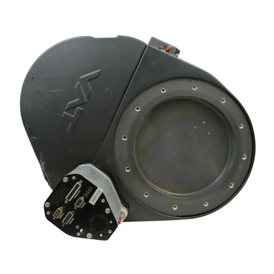
Pendulum control & isolation valve
with Logic interface
This manual is valid for the valve ordering number(s):
650 . . - . . GC - . . . .
650 . . - . . GE - . . . .
650 . . - . . AC - . . . .
650 . . - . . AE - . . . .
650 . . - . . HC - . . . .
650 . . - . . HE - . . . .
650 . . - . . CC - . . . .
650 . . - . . CE - . . . .
SPS = Sensor Power Supply
configured with firmware
The fabrication number is indicated on each product as per the label
below (or similar):
made in Switzerland
Fabrication No.:
patented
650 . . – . . . . – . . . . / . . . .
A – . . . . . .
Explanation of symbols:
Read declaration carefully before you start any other
action!
Attention!
Product is in conformity with EC guidelines!
Disconnect electrical power and compressed air
lines. Do not touch parts under voltage!
Read these «Installation, Operating & Maintenance Instructions» and the enclosed «General
Safety Instructions» carefully before you start any other action!
VAT Vakuumventile AG, CH-9469 Haag, Switzerland
Tel ++41 81 771 61 61 Fax ++41 81 771 48 30 Email
Installation, Operating & Maintenance Instructions
Series 650, DN 100 – 250 (I.D. 4" - 10")
(1 sensor input)
(2 sensor inputs)
(1 sensor input / ±15V SPS)
(2 sensor inputs / ±15V SPS)
(1 sensor input / PFO)
(2 sensor inputs / PFO)
(1 sensor input / ±15V SPS / PFO)
(2 sensor inputs / ±15V SPS / PFO)
PFO = Power Failure Option
650P.1D.00
. .
Fabrication number
reception@vat.ch www.vatvalve.com
Keep body parts and objects away from the valve
opening!
Hot surfaces; do not touch!
Loaded springs and/or air cushions are potential
hazards!
Wear gloves!
258550EE
2007-05-11
1/51
Advertisement
Table of Contents

Related Manuals for VAT 65040 Series


Summarization of Contents
1 Use of product
1.1 Technical Data
Provides detailed specifications, power consumption, and performance characteristics of the valve.
2 Installation
2.1 Unpacking and System Installation
Instructions for safely removing the valve and physically integrating it into the vacuum system.
2.3 Torque and Force Specifications
Details torque values for mounting and admissible mechanical forces to prevent damage.
2.5 Sensor and Electrical Connection
Covers requirements for sensor connection and detailed electrical wiring for operation.
3 Operation
3.1 Introduction & Modes
Overview of valve operation modes, local/remote control, and safety.
3.3 Power Behavior
Covers behavior during power up, power failure, and display information.
3.6 Setup Procedure
Step-by-step guide to configure the valve for pressure or position control.
3.10 Pressure Control Tuning
Parameters and procedures for tuning pressure control performance.
3.11 Logic Interface
Schematics and pin assignments for digital and analog inputs/outputs.
4 Trouble shooting
Troubleshooting Common Failures
Addresses common issues like remote operation failure, display errors, and control problems.
5 Maintenance & repairs
5.1 Maintenance Procedures
Outlines preventive maintenance tasks like seal replacement and cleaning.
5.2 Option Board and Replacement
Information on optional modules, battery life, and board replacement procedures.
6 Drawing
Valve Unit Diagram
Illustrates the physical components of the valve unit with numbered parts.
7 Spare parts and accessories
7.1 Accessories
Lists accessories like power supply units, software, and cables.
7.2 Control Unit Components
Details the control unit and available option boards for purchase.
7.3 Valve Unit Parts
Lists spare parts for the valve unit, including seals, plates, and actuators.
8 Warranty
Warranty Information
Outlines the terms and conditions of the product warranty provided by VAT.
Need help?
Do you have a question about the 65040 Series and is the answer not in the manual?
Questions and answers