Table of Contents
Advertisement
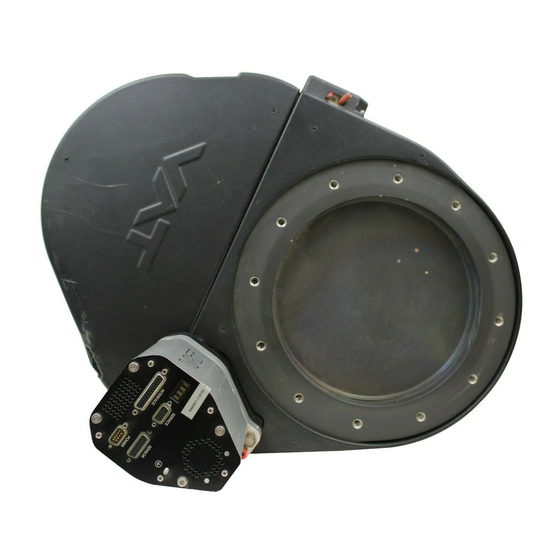
Pendulum control & isolation valve
with Logic interface
This manual is valid for the valve ordering number(s):
650 . . - . . GC - . . . .
650 . . - . . GE - . . . .
650 . . - . . AC - . . . .
650 . . - . . AE - . . . .
650 . . - . . HC - . . . .
650 . . - . . HE - . . . .
650 . . - . . CC - . . . .
650 . . - . . CE - . . . .
SPS = Sensor Power Supply
configured with firmware
The fabrication number is indicated on each product as per the label
below (or similar):
made in Switzerland
Fabrication No.:
patented
650 . . – . . . . – . . . . / . . . .
A – . . . . . .
Explanation of symbols:
Read declaration carefully before you start any other
action!
Attention!
Product is in conformity with EC guidelines!
Disconnect electrical power and compressed air
lines. Do not touch parts under voltage!
Read these «Installation, Operating & Maintenance Instructions» and the enclosed «General
Safety Instructions» carefully before you start any other action!
VAT Vakuumventile AG, CH-9469 Haag, Switzerland
Tel ++41 81 771 61 61 Fax ++41 81 771 48 30 Email
Installation, Operating & Maintenance Instructions
Series 650, DN 100 – 250 (I.D. 4" - 10")
(1 sensor input)
(2 sensor inputs)
(1 sensor input / ±15V SPS)
(2 sensor inputs / ±15V SPS)
(1 sensor input / PFO)
(2 sensor inputs / PFO)
(1 sensor input / ±15V SPS / PFO)
(2 sensor inputs / ±15V SPS / PFO)
PFO = Power Failure Option
650P.1D.00
. .
Fabrication number
reception@vat.ch www.vatvalve.com
Keep body parts and objects away from the valve
opening!
Hot surfaces; do not touch!
Loaded springs and/or air cushions are potential
hazards!
Wear gloves!
258550EE
2007-05-11
1/51
Advertisement
Table of Contents

Related Manuals for VAT 65044 Series


Summarization of Contents
Pendulum Control & Isolation Valve with Logic Interface
Explanation of Symbols
Explains the meaning of various symbols used in the manual.
Use of Product
Technical Data
Provides detailed specifications and technical parameters of the valve.
Installation
Unpacking
Step-by-step instructions for safely removing the valve from its packaging.
Installation into the System
Guidance on physically installing the valve within the vacuum system.
Tightening Torque
Specifies the correct torque values for mounting screws to prevent damage.
Admissible Forces
Details maximum forces the valve can withstand without deformation.
Sensor Connection Requirements
Guidelines for optimal sensor connection for accurate pressure control.
Electrical Connection
Information on wiring the valve's electrical interfaces.
Power and Sensor Connection (+24 VDC)
Wiring diagram for +24VDC power and sensor inputs.
Power and Sensor Connection (±15 VDC) without SPS
Wiring for ±15VDC sensors without SPS module.
Power and Sensor Connection (±15 VDC) with SPS
Wiring for ±15VDC sensors with optional SPS module.
Logic Interface Connection
Details on connecting the logic interface for remote control.
Service Port Connection
Information on connecting the valve to a computer via the service port.
Operation
Introduction to Operation
Overview of the valve's purpose and operating modes.
Local Operation
How to operate the valve using a computer via the service port.
Remote Operation
Operating the valve using digital and analog signals.
Safety Mode
Description of the safety mode and its behavior.
Behavior During Power Up
How the valve reacts upon receiving power.
Behavior in Case of Power Failure
How the valve behaves when power is interrupted.
Display Information
Explains the 4-digit display and its status indications.
Setup Procedure
Step-by-step guide to configure the valve for operation.
Interface Configuration
How to configure digital inputs and outputs for interface control.
Valve and Sensor Configuration
Setting valve position and sensor parameters.
ZERO Function
Procedure for compensating sensor offset voltage.
LEARN Function
Adapting PID controller to vacuum system characteristics.
Close Valve
Instructions for closing the valve locally or remotely.
Open Valve
Instructions for opening the valve locally or remotely.
Position Control
How to control the valve's position directly.
Pressure Control
Steps to prepare and perform pressure control.
Pressure Control with 2 Sensors
How to use two sensors for pressure control.
Tuning Control Performance
Adjusting parameters for optimal pressure control.
Gain Factor Adjustment
Adjusting the gain factor for stability and response time.
Sensor Delay Adjustment
Adjusting sensor delay to improve stability.
Setpoint Ramp Adjustment
Defining time for pressure changes between setpoints.
Valve Speed Adjustment
Adjusting the speed of valve plate actuation.
Logic Interface and Signals
Details digital and analog signal interfaces for remote operation, including schematics and I/O details.
Troubleshooting
Common Failures and Solutions
Lists common issues, their checks, and recommended actions.
Pressure Reading Issues
Troubleshooting steps for incorrect or negative pressure readings.
ZERO Function Issues
Troubleshooting steps when the ZERO function does not work.
Pressure Control Issues
Troubleshooting steps for pressure control not working or being suboptimal.
Maintenance & Repairs
Maintenance Procedures
General guidelines for performing maintenance and repairs on the valve.
Seal Replacement and Valve Cleaning
Procedure for replacing isolation seals and cleaning the valve.
Actuator Feedthrough Seal Replacement
Procedure for replacing actuator feedthrough seals.
Option Board and Battery Durability
Information on option boards, modules, and power fail battery life.
Retrofit/Replacement Procedure
Steps for retrofitting or replacing the option board.
Drawing
Valve Unit Component Diagram
A diagram illustrating the main components of the valve unit.
Spare Parts and Accessories
Accessories
List of available accessories such as power supply and software.
Control Unit Components
Information on control units and option boards.
Valve Unit Parts List
Part numbers for various valve unit components like bonnet, seals, and actuators.
Warranty
Warranty Terms and Conditions
Details the warranty provided by VAT for their products.
Need help?
Do you have a question about the 65044 Series and is the answer not in the manual?
Questions and answers