
Related Manuals for H3C RA100


Summary of Contents for H3C RA100
- Page 1 H3C RA100 Router Installation Guide New H3C Technologies Co., Ltd. http://www.h3c.com.hk Document version: 6W100-20170608...
- Page 2 , H3CS, H3CIE, H3CNE, Aolynk, Care, , IRF, NetPilot, Netflow, SecEngine, SecPath, SecCenter, SecBlade, Comware, ITCMM and HUASAN are trademarks of New H3C Technologies Co., Ltd. All other trademarks that may be mentioned in this manual are the property of their respective owners Notice The information in this document is subject to change without notice.
- Page 3 Audience This documentation is intended for: • Network planners • Field technical support and servicing engineers • Network administrators working with the RA100 Router Conventions The following information describes the conventions used in the documentation. Command conventions Convention Description Boldface Bold text represents commands and keywords that you enter literally as shown.
- Page 4 Symbols Convention Description An alert that calls attention to important information that if not understood or followed WARNING! can result in personal injury. An alert that calls attention to important information that if not understood or followed CAUTION: can result in data loss, data corruption, or damage to hardware or software. An alert that calls attention to essential information.
- Page 5 Obtaining documentation To access the most up-to-date H3C product documentation, go to the H3C website at http://www.h3c.com.hk To obtain information about installation, configuration, and maintenance, click http://www.h3c.com.hk/Technical_Documents To obtain software version information such as release notes, click http://www.h3c.com.hk/Software_Download Technical support service@h3c.com...
-
Page 6: Table Of Contents
Contents Preparing for installation ················································································· 1 Safety recommendations ··································································································································· 1 Safety symbols ··········································································································································· 1 General safety recommendations ·············································································································· 1 Electricity safety ········································································································································· 1 Examining the installation site ···························································································································· 1 Temperature and humidity ························································································································· 1 ... - Page 7 Technical specifications ··································································································································· 24 Appendix B LEDs ·························································································· 25 Index ············································································································· 27 ...
-
Page 8: Preparing For Installation
Preparing for installation Safety recommendations Safety symbols When reading this document, note the following symbols: WARNING means an alert that calls attention to important information that if not understood or followed can result in personal injury. CAUTION means an alert that calls attention to important information that if not understood or followed can result in data loss, data corruption, or damage to hardware or software. -
Page 9: Cleanliness
Table 1 Temperature and humidity requirements Temperature Relative humidity –20°C to +60°C (–4°F to +140°F) 5% to 90%, noncondensing Cleanliness Dust buildup on the chassis might result in electrostatic adsorption, which causes poor contact of metal components and contact points, especially when indoor relative humidity is low. In the worst case, electrostatic adsorption can cause communication failure. -
Page 10: Emi Prevention
The router does not provide an ESD wrist strap, prepare it yourself. To attach an ESD wrist strap: Wear the wrist strap on your wrist. Lock the wrist strap tight around your wrist to maintain good contact with the skin. Secure the wrist strap lock and the alligator clip lock together. -
Page 11: Pre-Installation Checklist
Figure 2 Installation accessories Pre-installation checklist Item Requirements • A minimum clearance of 10 cm (3.9 in) is reserved around the air inlet and outlet vents. Ventilation • The installation site has a good ventilation system. Temperature –20°C to +60°C (–4°F to +140°F) Relative humidity 5% to 90% (noncondensing) Dust concentration ≤... - Page 12 Item Requirements • The router is far away from any sources of heat or moisture. Safety • precautions The emergency power switch in the equipment room is identified and accessible. Installation • Installation accessories supplied with the router are ready. tools and •...
-
Page 13: Installing The Router
Installing the router WARNING! To avoid injury, do not touch bare wires, terminals, or parts with high-voltage hazard signs. Installation prerequisites • You have read "Preparing for installation" carefully. • All requirements in "Preparing for installation" are met. Installation flowchart You can install the router on a workbench, on a wall, or in a rack. -
Page 14: Installing The Router In A Rack
Figure 3 Installation flowchart Installing the router in a rack CAUTION: The mounting brackets can support only the weight of the router. Do not place any objects on the router. Mounting the router in a 19-inch rack Use a 19-inch rack mounting bracket to mark the cage nut installation holes in the front rack posts, as shown in Figure Make sure the cage nut installation holes on the front rack posts are on a horizontal line. - Page 15 Figure 4 Marking cage nut installation holes Install cage nuts, as shown in Figure a. Insert one ear of a cage nut into the marked installation hole. b. Use a flathead screwdriver to push another ear into the same hole. Figure 5 Installing cage nuts Use screws to attach mounting brackets to both sides of the router, as shown in Figure...
-
Page 16: Mounting The Router In An Etsi Rack
Figure 6 Attaching mounting brackets to the router Supporting the router at the bottom with one hand, use screws to attach the mounting brackets on the router to the front rack posts with the other hand. Figure 7 Securing the router to the rack Mounting the router in an ETSI rack Perform the following tasks as shown in "Mounting the router in a 19-inch... -
Page 17: Mounting The Router On A Workbench
Figure 8 Attaching ETSI rack mounting brackets Supporting the router at the bottom with one hand, use screws to attach the mounting brackets on the router to the front rack posts with the other hand. Figure 9 Securing the router to the ETSI rack Mounting the router on a workbench IMPORTANT: •... -
Page 18: Installing The Router On A Wall
To mount the router on a workbench: Place the router upside down on the workbench and attach the rubber feet to the four round holes in the chassis bottom. Figure 10 Attaching rubber feet to the router Place the router upside up on the workbench. Make sure the rubber feet stand securely on the workbench. - Page 19 Figure 12 Drilling holes in a wall Attach 19-inch rack mounting brackets to both sides of the router. Figure 13 Attaching mounting brackets to the router Align the screw holes in the mounting brackets with the holes in the wall, and use M6 screws to secure the router on the wall.
-
Page 20: Grounding The Router Through The Grounding Terminal On The Rack
Figure 14 Installing the router on the wall Grounding the router through the grounding terminal on the rack CAUTION: • Correctly connecting the grounding cable is crucial to lightning protection and EMI protection. • Ensure a minimum resistance of 5 ohms between the router and the ground. •... -
Page 21: Connecting Interface Cables
Figure 15 Grounding the router through the grounding terminal on the rack Connecting interface cables Connect cables to the interfaces on the router before powering on the router. The following uses an Ethernet copper port and an Ethernet fiber port as examples to describe the cable connection procedures. -
Page 22: Connecting An Ethernet Optical Fiber
Figure 16 Connecting an Ethernet copper cable Connecting an Ethernet optical fiber WARNING! Do not stare into any open apertures of operating transceiver modules or optical fiber connectors. The laser light emitted from these apertures might hurt your eyes. CAUTION: •... -
Page 23: Connecting The Console Cable And Setting Terminal Parameters
Connecting the console cable and setting terminal parameters To access the router for the first time, use a console cable to connect the console port on the router. Connecting the console cable CAUTION: The serial ports on PCs do not support hot swapping. To connect a PC to an operating router, first connect the PC end. -
Page 24: Connecting The Power Cord
Connecting the power cord Connecting the DC power cord Make sure the router is reliably grounded. Connect one end of the power cord to the DC-input receptacle on the router. Connect the other end of the power cord to the DC power source. Figure 19 Connecting the DC power cord Connecting the AC power cord Make sure the router is reliably grounded. -
Page 25: Verifying The Installation
Figure 20 Connecting the AC power cord Verifying the installation Verify the following items before you power on the router: • There is enough space around the router for heat dissipation. • The router is reliably grounded. • The power source is as required by the router. •... - Page 26 Do you want to check SDRAM? [Y/N] Booting Normal Extended BootWare The Extended BootWare is self-decompressing..Done. **************************************************************************** H3C RA100 BootWare, Version 0.11 **************************************************************************** Copyright (c) 2004-2017 New H3C Technologies Co., Ltd. Compiled Date : Feb 14 2014 CPU ID : 0xb Memory Type...
-
Page 27: Troubleshooting
• Keep the tamper-proof seal on a mounting screw on the chassis cover intact, and if you want to open the chassis, contact H3C for permission. Otherwise, H3C shall not be liable for any consequence. -
Page 28: Garbled Display On The Configuration Terminal
Verify that the console cable is in good condition. If the problem persists, contact H3C Support. Garbled display on the configuration terminal Symptom The configuration terminal has garbled display when the router is powered on. Solution To resolve the problem: Verify that the Data bits field is set to 8 for the terminal. -
Page 29: Scenario 2
Scenario 2 Symptom The router cannot connect to the network after configuration modifications. The configuration is very complicated and it is hard to locate the errors. Solution If you have not saved any configuration, you can reboot the router by pressing the RESET button for a short time or power off the router. -
Page 30: Appendix A Chassis Views And Technical Specifications
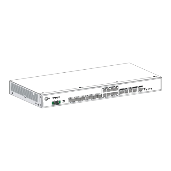
Appendix A Chassis views and technical specifications Chassis views The following figures are for illustration only. Figure 21 RA100-DC front panel (1) Grounding terminal (2) ALMI/ALMO port (3) TOD port (4) CLK port (5) Management Ethernet port (6) Console port... - Page 31 Technical specifications Table 4 Technical specifications Item Specification Dimensions (H × W × D) (excluding rubber 44.2 × 440 × 205 mm (1.74 × 17.32 × 8.07 in) feet and mounting brackets) Memory 1 GB DDR3 Flash 256 MB Rated AC voltage 100 VAC to 240 VAC @ 50 to 60 Hz Rated DC voltage –48VDC to –60VDC...
- Page 32 Appendix B LEDs Figure 23 RA100-DC LEDs (1) Alarm LED (ALM) (2) Clock synchronization LED (SYNC) (3) System status LED (SYS) (4) GE fiber port LED (5) GE copper port LED (6) Power status LED (PWR) Figure 24 RA100 LEDs...
- Page 33 Status Description BootWare is starting and the system software image is Flashing green (8 Hz) being copied and decompressed. This phase starts 10 seconds after the router is powered on. Steady green The device is being initialized. System status LED Comware has started with the configuration file and the Flashing green (1 Hz) (SYS)
- Page 34 Index C E G L M R S T Mounting the router in an ETSI rack,9 Cleanliness,2 Connecting an Ethernet copper cable,14 Reset button usage guidelines,22 Connecting an Ethernet optical fiber,15 Connecting the AC power cord,17 Safety symbols,1 Connecting the console cable,16 Scenario 1,21...
Need help?
Do you have a question about the RA100 and is the answer not in the manual?
Questions and answers