H3C MSR810 Installation Manual
Hide thumbs
Also See for MSR810:
- Command reference manual (389 pages) ,
- Safety manual (64 pages) ,
- Installation manual (46 pages)

Related Manuals for H3C MSR810


Summary of Contents for H3C MSR810
- Page 1 H3C MSR810 Routers Installation Guide New H3C Technologies Co., Ltd. http://www.h3c.com Document version: 6W108-20190528...
- Page 2 The information in this document is subject to change without notice. All contents in this document, including statements, information, and recommendations, are believed to be accurate, but they are presented without warranty of any kind, express or implied. H3C shall not be liable for technical or editorial errors or omissions contained herein.
- Page 3 Preface The H3C MSR810 Routers Installation Guide includes five chapters, which describe the preparing for installation, installing the router, troubleshooting, chassis views and technical specifications, and LEDs. This preface includes the following topics about the documentation: • Audience. • Conventions.
- Page 4 Convention Description Multi-level menus are separated by angle brackets. For example, File > Create > > Folder. Symbols Convention Description An alert that calls attention to important information that if not understood or followed WARNING! can result in personal injury. An alert that calls attention to important information that if not understood or followed CAUTION: can result in data loss, data corruption, or damage to hardware or software.
- Page 5 It is normal that the port numbers, sample output, screenshots, and other information in the examples differ from what you have on your device. Documentation feedback You can e-mail your comments about product documentation to info@h3c.com. We appreciate your comments.
-
Page 6: Table Of Contents
Lightning protection ············································································································· 4 Installation accessories and tools ·································································································· 5 Installation accessories (RT-MSR810/RT-MSR810-W/RT-MSR810-W-DB/RT-MSR810-LM/RT-MSR810- LM-CNDE-SJK/RT-MSR810-W-LM/RT-MSR810-10-PoE/RT-MSR810-LM-HK/RT-MSR810-W-LM- HK/RT-MSR810-LM-GL/RT-MSR810-W-LM-GL) ······································································· 5 Installation accessories (RT-MSR810-LME/RT-MSR810-LMS/RT-MSR810-LMS-EA/RT-MSR810-LUS) 6 Installation tools ·················································································································· 6 Pre-installation checklist ·············································································································· 6 Installing the router ··········································································· 8 ... - Page 7 Scenario 3 ······················································································································· 31 Reset button usage guidelines ····························································································· 31 Appendix A Chassis views and technical specifications ·························· 32 Chassis views ························································································································· 32 RT-MSR810 ····················································································································· 32 RT-MSR810-W ················································································································· 33 RT-MSR810-W-DB ············································································································ 34 RT-MSR810-LM ················································································································ 35 ...
-
Page 8: Preparing For Installation
Preparing for installation The H3C MSR810 router series includes the models in Table Table 1 H3C MSR810 router series models Model (marked on the front panel) Product code RT-MSR810-W RT-MSR810-W-DB H3C MSR810 RT-MSR810-LM RT-MSR810-W-LM RT-MSR810 RT-MSR810-10-PoE RT-MSR810-LM-HK RT-MSR810-LM-CNDE-SJK RT-MSR810-W-LM-HK H3C MSR810 Series... -
Page 9: Electricity Safety
• Place the router in a dry and flat location and make sure anti-slip measures are in place. • Remove all external interface cables and power cords before moving the router. Electricity safety • Locate the power switch of the power source before installation. Shut off the power immediately if an accident occurs. -
Page 10: Cleanliness
Table 2 Temperature/humidity requirements in the equipment room Model Operating temperature Operating humidity • H3C MSR810 RT-MSR810-W RT-MSR810-W-DB RT-MSR810-LM RT-MSR810-W-LM • H3C MSR810 Series RT-MSR810 0°C to 40°C (32°F to 104°F) 5% RH to 90% RH, noncondensing RT-MSR810-LM- CNDE-SJK RT-MSR810-10-PoE RT-MSR810-LM-HK RT-MSR810-W-LM- RT-MSR810-LM-GL RT-MSR810-W-LM-GL •... -
Page 11: Cooling
Cooling • Maintain a minimum clearance of 100 mm (3.94 in) around the air vents. • Make sure the installation site has a good ventilation system. All electromagnetic interference (EMI) sources, from outside or inside of the router and application system, adversely affect the router in the following ways: •... -
Page 12: Installation Accessories And Tools
4G antenna WLAN antenna Ring terminal (optional) supplied) Mounting brackets and screws (provided only with the Screw anchor and screw Rubber feet RT-MSR810-10-PoE and optional for other models) (user supplied) Table 5 Antenna compatibility Model 4G antenna WLAN antenna • RT-MSR810-LM •... -
Page 13: Installation Accessories (Rt-Msr810-Lme/Rt-Msr810-Lms/Rt-Msr810-Lms-Ea/Rt-Msr810-Lus)
Installation accessories (RT-MSR810-LME/RT-MSR810- LMS/RT-MSR810-LMS-EA/RT-MSR810-LUS) Figure 2 Installation accessories The RT-MSR810-LME, RT-MSR810-LMS, and RT-MSR810-LUS routers are not shipped with 4G antennas. Installation tools No installation tools are provided with the router. Prepare them yourself as required. Figure 3 Installation tools and equipment... - Page 14 Item Requirements Result humidity RT-MSR810 RT-MSR810-W RT-MSR810-W-DB RT-MSR810-LM RT-MSR810-LM-CNDE-SJK RT-MSR810-W-LM RT-MSR810-10-PoE RT-MSR810-LM-HK RT-MSR810-W-LM-HK RT-MSR810-LM-GL RT-MSR810-W-LM-GL • 0% to 95% (noncondensing): RT-MSR810-LME RT-MSR810-LMS RT-MSR810-LMS-EA RT-MSR810-LUS: Dust concentration ≤ 3 × 10 particles/m (no visible dust Cleanness on the tabletop over three days) •...
-
Page 15: Installing The Router
• Keep the tamper-proof seal on a mounting screw on the chassis cover intact, and if you want to open the chassis, contact H3C for permission. Otherwise, H3C shall not be liable for any consequence. -
Page 16: Installing The Router
Figure 4 Installation flowchart Start Determine the installation position Mount the router on a Mount the router on a Mount the router in a rack workbench wall Connect the grounding cable Install antennas Connect interface cables Connect the router to a configuration terminal Connect the power adapter or power cord... -
Page 17: Mounting The Router On A Wall
Figure 5 Mounting the router on a workbench Mounting the router on a wall Only the following routers support wall mounting: • RT-MSR810 • RT-MSR810-LM • RT-MSR810-LM-CNDE-SJK • RT-MSR810-W-DB • RT-MSR810-W • RT-MSR810-W-LM • RT-MSR810-LM-HK • RT-MSR810-W-LM-HK • RT-MSR810-LM-GL •... -
Page 18: Installing The Router In A Rack
The mounting brackets can support only the weight of the router. Do not place objects on the router. Mounting brackets and screws are provided with the RT-MSR810-10-PoE and are optional for the other models. The RT-MSR810-LME, RT-MSR810-LMS, RT-MSR810-LMS-EA, and RT-MSR810-LUS routers do not support rack mounting. - Page 19 Figure 7 Marking cage nut installation holes Install the cage nuts, as shown in Figure a. Insert one ear of a cage nut into the marked installation hole. b. Use a flathead screwdriver to push another ear into the same hole. Figure 8 Installing cage nuts Attach mounting brackets to both sides of the router, as shown in Figure...
- Page 20 Figure 9 Attaching mounting brackets to the router Use M6 screws to attach the mounting brackets on the router to the front rack posts, as shown in Figure Figure 10 Securing the router to the rack...
-
Page 21: Grounding The Router
Grounding the router CAUTION: • Correctly connecting the grounding cable is crucial to lightning protection and EMI protection. When you install and use the router, first ground the router reliably. • Ensure a minimum resistance of 5 ohms between the router and the ground. The router provides only a ring terminal. -
Page 22: Grounding The Router With A Grounding Conductor Buried In The Earth Ground
Use the grounding screw to attach the ring terminal of the grounding cable to the grounding hole. Use a screwdriver to fasten the grounding screw. Connect the other end of the grounding cable to the grounding strip. Figure 12 Connecting the grounding cable to the router Grounding screw Grounding... -
Page 23: Installing A 4G Sim Card
Remove the screw on the 4G SIM card slot cover and take off the cover. Insert the 4G SIM card into the SIM card slot along the guide rails. Reinstall the cover and fasten the screw on the cover. Figure 14 Installing a 4G SIM card (RT-MSR810-LMS/RT-MSR810-LUS) Installing a Micro SD card CAUTION: To avoid damaging the Micro SD card slot, do not use excessive force when you install a Micro SD card. -
Page 24: Installing An Sd Card
• The router cannot read data from or write data into a SD card if the SD card is in write protection state. Only the RT-MSR810-10-PoE router supports SD cards. To install an SD card: Remove the screw on the SD card slot cover and take off the cover. -
Page 25: Installing A 4G Antenna
• RT-MSR810-LMS-EA • RT-MSR810-LUS No 4G antenna is provided with the RT-MSR810-LME, RT-MSR810-LMS, and RT-MSR810-LUS routers. Purchase one yourself if required. To install a 4G antenna: Change the angle of the antenna orientation from vertical to horizontal. Attach the 4G antenna to the 4G antenna port on the router. Do not over-tighten the antenna to avoid damage. -
Page 26: Installing A Wlan Antenna
• RT-MSR810-W-LM-HK • RT-MSR810-W-LM-GL You can install two WLAN antennas for the RT-MSR810-W, RT-MSR810-W-LM, RT-MSR810-W- LM-HK, and RT-MSR810-W-LM-GL routers and four WLAN antennas for the RT-MSR810-W-DB router. To install a WLAN antenna: Change the angle of the antenna orientation from vertical to horizontal. -
Page 27: Installing A Gps Antenna
Figure 18 Installing WLAN antennas Installing a GPS antenna Only the routers support a GPS antenna: • RT-MSR810-LM • RT-MSR810-LM-CNDE-SJK • RT-MSR810-W-LM • RT-MSR810-LM-HK • RT-MSR810-W-LM-HK • RT-MSR810-LM-GL • RT-MSR810-W-LM-GL To install a GPS antenna: Attach the male connector of the GPS antenna to the GPS antenna port on the router. -
Page 28: Supplying Power To A Terminal Through Poe
Figure 19 Installing a GPS antenna Supplying power to a terminal through PoE Only the RT-MSR810-10-PoE router supports PoE. To supply power to a terminal, the terminal must support PoE. To supply power to a terminal through PoE: Connect one end of the cable to an Ethernet port on the router. -
Page 29: Connecting Ethernet Interface Cables
Figure 20 Supplying power to a terminal Connecting Ethernet interface cables Connect one end of the cable to an Ethernet port on the router. Connect the other end of the cable to the Ethernet port on a host. Examine the port LEDs on the router. For more information about the LEDs, see "LED description."... -
Page 30: Connecting The Console Cable And Setting Terminal Parameters
Connecting the console cable and setting terminal parameters Connecting the console cable CAUTION: The serial ports on PCs do not support hot swapping. To connect a PC to an operating router, first connect the PC end. To disconnect a PC from an operating router, first disconnect the router end. To connect the console cable: Select a configuration terminal, which can be an ASCII terminal with an RS-232 serial port or a PC. -
Page 31: Connecting The Power Adapter Or Power Cord
Connecting the power adapter or power cord CAUTION: The power adapter kit provided with the RT-MSR810-LMS-EA router includes UK, EU, and TH power plugs. Use a power plug that follows the standards of the country or region to assemble the power adapter. - Page 32 Figure 23 Connecting the power adapter (RT-MSR810/MSR810-LM/RT-MSR810-LM-CNDE- SJK/RT-MSR810-W-DB/RT-MSR810-W/RT-MSR810-W-LM/RT-MSR810-LM-HK/RT-MSR810-W- LM-HK/RT-MSR810-LM-GL/RT-MSR810-W-LM-GL) Figure 24 Assembling the RT-MSR810-LMS-EA adapter Figure 25 Connecting the power adapter (RT-MSR810-LME/RT-MSR810-LMS/RT-MSR810- LMS-EA/RT-MSR810-LUS)
-
Page 33: Connecting The Power Cord
Connect the power cord to the AC receptacle. Insert the AC output plug of the power cord to the power adapter receptacle on the router. Figure 26 Connecting the power cord for the RT-MSR810-10-PoE Verifying the installation After you complete the installation, verify the following information: •... - Page 34 Press Ctrl+D to access BASIC-BOOTWARE MENU Booting Normal Extend BootWare Do you want to check SDRAM? [Y/N] **************************************************************************** H3C MSR810 BootWare, Version 1.03 **************************************************************************** Copyright (c) 2004-2018 New H3C Technologies Co., Ltd. Compiled Date : Mar 20 2018 CPU ID : 0xa CPU L1 Cache...
- Page 35 Configure basic settings for the router. For information about configuring basic setting for the router, see Fundamentals Configuration Guide in H3C MSR810[2600][3600] Router Series Comware 7 Configuration Guides and Fundamentals Command Reference in H3C MSR810[2600][3600] Router Series Comware 7 Command References.
-
Page 36: Troubleshooting
• Keep the tamper-proof seal on a mounting screw on the chassis cover intact, and if you want to open the chassis, contact H3C for permission. Otherwise, H3C shall not be liable for any consequence. -
Page 37: Garbled Display On The Configuration Terminal
Verify that the following settings are configured for the terminal: Baud rate—9,600. Data bits—8. Parity—None. Stop bits—1. Flow control—None. If the issue persists, contact H3C Support. No response from the serial port Symptom The serial port on the router does not respond Solution To resolve the issue: Verify that the serial cable is in good condition and the serial port settings are correct. -
Page 38: Restoring The Factory Settings
Restoring the factory settings Scenario 1 Symptom When you replace the router, the router password is lost. As a result, you cannot log in to the router and do not know the router configuration. Solution Because the router is replaced, you do not need to save the configuration of the router. In this case, you can press the RESET button for more than 4 seconds to reboot the router and restore the factory settings. -
Page 39: Appendix A Chassis Views And Technical Specifications
Appendix A Chassis views and technical specifications Chassis views The figures in this appendix are for illustration only. RT-MSR810 Figure 27 Front view (1) Power adapter receptacle (2) Gigabit Ethernet LAN ports (GE1 to GE4) (3) Gigabit Ethernet WAN port (GE0) -
Page 40: Rt-Msr810-W
RT-MSR810-W Figure 29 Front view (1) Power adapter receptacle (2) Gigabit Ethernet LAN ports (GE1 to GE4) (3) Gigabit Ethernet WAN port (GE0) (4) Gigabit fiber port (SFP5) (5) Console port (6) USB port 0 (7) Micro SD card slot... -
Page 41: Rt-Msr810-W-Db
RT-MSR810-W-DB Figure 31 Front view (1) Power adapter receptacle (2) Gigabit Ethernet LAN ports (GE1 to GE4) (3) Gigabit Ethernet WAN ports (GE0) (4) Gigabit fiber port (SFP5) (5) Console port (6) USB port 0 (7) Micro SD card slot... -
Page 42: Rt-Msr810-Lm
RT-MSR810-LM Figure 33 Front view (1) Power adapter receptacle (2) Gigabit Ethernet LAN ports (GE1 to GE4) (3) Gigabit Ethernet WAN port (GE0) (4) Gigabit fiber port (SFP5) (5) Console port (6) USB port (7) Micro SD card slot (8) Reset button (RESET) -
Page 43: Rt-Msr810-Lm-Cnde-Sjk
RT-MSR810-LM-CNDE-SJK Figure 35 Front view (1) Power adapter receptacle (2) Gigabit Ethernet LAN ports (GE1 to GE4) (3) Gigabit Ethernet WAN port (GE0) (4) Gigabit fiber port (SFP5) (5) Console port (6) USB port (7) Micro SD card slot (8) Reset button (RESET) -
Page 44: Rt-Msr810-W-Lm
RT-MSR810-W-LM Figure 37 Front view (1) Power adapter receptacle (2) Gigabit Ethernet LAN ports (GE1 to GE4) (3) Gigabit Ethernet WAN port (GE0) (4) Gigabit fiber port (SFP5) (5) Console port (6) USB port (7) Micro SD card slot (8) Reset button (RESET) -
Page 45: Rt-Msr810-10-Poe
RT-MSR810-10-PoE Figure 39 Front view (1) Gigabit Ethernet LAN ports (GE2 to GE9) (2) Gigabit Ethernet WAN port (GE0) (3) Gigabit combo interface (GE1/SFP1) (4) Console port (5) Reset button (RESET) (6) USB port (7) SD card slot Figure 40 Rear view... -
Page 46: Rt-Msr810-W-Lm-Hk
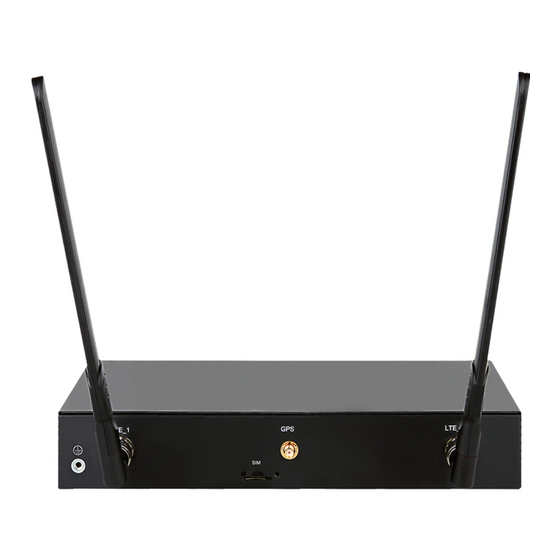
(2) LTE antenna port 1 (3) 4G SIM card slot (4) GPS antenna port (5) LTE antenna port 2 RT-MSR810-W-LM-HK Figure 43 Front view (1) Power adapter receptacle (2) Gigabit Ethernet LAN ports (GE1 to GE4) (3) Gigabit Ethernet WAN port (GE0) -
Page 47: Rt-Msr810-Lm-Gl
RT-MSR810-LM-GL Figure 45 Front view (1) Power adapter receptacle (2) Gigabit Ethernet LAN ports (GE1 to GE4) (3) Gigabit Ethernet WAN port (GE0) (4) Gigabit fiber port (SFP5) (5) Console port (6) USB port (7) Micro SD card slot (8) Reset button (RESET) -
Page 48: Rt-Msr810-W-Lm-Gl
RT-MSR810-W-LM-GL Figure 47 Front view (1) Power adapter receptacle (2) Gigabit Ethernet LAN ports (GE1 to GE4) (3) Gigabit Ethernet WAN port (GE0) (4) Gigabit fiber port (SFP5) (5) Console port (6) USB port (7) Micro SD card slot (8) Reset button (RESET) -
Page 49: Rt-Msr810-Lme
RT-MSR810-LME Figure 49 Front view (1) LTE antenna port (2) DC power receptacle (3) USB port (4) Reset button (RESET) (5) Megabit Ethernet ports (FE0 to FE3) Figure 50 Rear view (1) Console port (2) 4G SIM card slots (SIM0 and SIM1) -
Page 50: Technical Specifications
Figure 52 Rear view (1) Console port (2) Grounding screw (3) 4G SIM card slots (SIM0 and SIM1) Technical specifications Table 6 Technical specifications (1) Item RT-MSR810 RT-MSR810-W RT-MSR810-W-DB RT-MSR810-10-PoE Console port USB port 2 (one combo copper GE WAN port... - Page 51 Item RT-MSR810 RT-MSR810-W RT-MSR810-W-DB RT-MSR810-10-PoE 100 VAC to 100 VAC to 240 100 VAC to 240 VAC 100 VAC to 240 VAC Input voltage 240 VAC @ VAC @ 50 to @ 50 to 60Hz @ 50 to 60Hz 50 to 60Hz...
- Page 52 RT-MSR810- RT-MSR810- RT-MSR810- RT-MSR810- RT-MSR810- Item LM-CNDE- W-LM LM-HK W-LM-HK Dimensions (H × W × D) 43.6 × 266 × 43.6 × 266 × 43.6 × 266 × 43.6 × 266 × 43.6 × 266 × (excluding 161 mm (1.72 161 mm (1.72...
- Page 53 RT-MSR810- Item RT-MSR810-LME RT-MSR810-LMS RT-MSR810-LUS LMS-EA WLAN antenna port GPS antenna Reserved Reserved Reserved port Memory 1 GB DDR3 512 MB DDR3 1 GB DDR3 512 MB DDR3 Flash 256 MB 256 MB 256 MB 256 MB Dimensions (H × W × D) 35 ×...
- Page 54 Item RT-MSR810-LM-GL RT-MSR810-W-LM-GL 4G LET antenna port WLAN antenna port GPS antenna port Memory 1 GB DDR3 1 GB DDR3 Flash 256 MB 256 MB Dimensions (H × W × D) (excluding 43.6 × 266 × 161 mm (1.72 × 10.47 ×...
- Page 55 Table 11 Specifications for the 4G antenna with a 3 m (9.84 ft) extension cable Item Specification • 680 to 960 MHz Frequency range • 1710 to 2700 MHz Voltage standing wave ratio (VSWR) Input impedance 50 ohms Gain 2 dBi (peak) Polarization Vertical Max input power...
- Page 56 Item Specification Weight 25 g (0.88 oz ) Operating temperature –40°C to +85°C (–40°F to +185°F)
-
Page 57: Appendix B Leds
Appendix B LEDs LEDs An MSR810 router provides a RESET button for rebooting the system and restoring the factory default settings. Press the RESET button for a short time to reboot the router. Press the RESET button for more than 4 seconds to reboot the router and restore the factory settings. -
Page 58: Rt-Msr810-W-Db
RT-MSR810-W-DB Figure 55 Front panel LEDs (1) GE port yellow LED (2) GE port green LED (3) 5G WLAN LED (4) 2.4G WLAN LED (5) VPN status LED (6) System status LED (SYS) (7) Micro SD card LED (8) SFP port LED... -
Page 59: Rt-Msr810-Lm-Cnde-Sjk
RT-MSR810-LM-CNDE-SJK Figure 57 Front panel LEDs (1) GE port yellow LED (2) GE port green LED (3) VPN status LED (4) System status LED (SYS) (5) Micro SD card LED (6) LTE LED (7) CNDE LED (8) SFP port LED... -
Page 60: Rt-Msr810-10-Poe
RT-MSR810-10-PoE Figure 59 Front panel LEDs (1) SD card LED (2) PoE LED (3) VPN status LED (4) System status LED (SYS) RT-MSR810-LM-HK Figure 60 Front panel LEDs (1) GE port yellow LED (2) GE port green LED (3) VPN status LED... -
Page 61: Rt-Msr810-W-Lm-Hk
RT-MSR810-W-LM-HK Figure 61 Front panel LEDs (1) GE port yellow LED (2) GE port green LED (3) CNDE LED (4) 2.4G WLAN LED (5) VPN status LED (6) System status LED (SYS) (7) Micro SD card LED (8) LTE LED... -
Page 62: Rt-Msr810-W-Lm-Gl
RT-MSR810-W-LM-GL Figure 63 Front panel LEDs (1) GE port yellow LED (2) GE port green LED (3) CNDE LED (4) 2.4G WLAN LED (5) VPN status LED (6) System status LED (SYS) (7) Micro SD card LED (8) LTE LED... -
Page 63: Rt-Msr810-Lms/Rt-Msr810-Lms-Ea/Rt-Msr810-Lus
RT-MSR810-LMS/RT-MSR810-LMS-EA/RT-MSR810-LUS Figure 65 Front panel LEDs (1) System status LED (SYS) (2) VPN status LED (3) SIM0 slot LED (4) SIM1 slot LED (5) Signal strength LED (6) FE port LEDs (FE0 through FE3) LED description Status Description Steady green The SDRAM is performing self-test. - Page 64 Status Description The Micro SD card is present and has passed the Steady green test. Micro SD card LED No Micro SD card is inserted or the Micro SD card is installed incorrectly. Steady green A 4G link is present. Flashing green (8 Hz) Data is being received or transmitted on a 4G link.
- Page 65 Status Description Steady green A 1000 Mbps link is present. Flashing green Data is being received or transmitted at 1000 Mbps. SFP port LED Steady yellow A 10/100 Mbps link is present. Flashing yellow Data is being received or transmitted at 10/100 Mbps. No link is present.
Need help?
Do you have a question about the MSR810 and is the answer not in the manual?
Questions and answers