Table of Contents
Advertisement
Quick Links
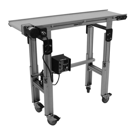
Ready-To-Run Mini Conveyors
Installation, Maintenance & Parts Manual
DORNER MFG. CORP.
P.O. Box 20 • 975 Cottonwood Ave.
Hartland, WI 53029-0020 USA
851-712 Rev. C
For other service manuals visit our website at:
www.dorner.com/service_manuals.asp
INSIDE THE USA
TEL: 1-800-397-8664
FAX: 1-800-369-2440
OUTSIDE THE USA
TEL: 262-367-7600
FAX: 262-367-5827
Advertisement
Table of Contents

Related Manuals for Dorner Ready-To-Run Mini Conveyors


Summary of Contents for Dorner Ready-To-Run Mini Conveyors
- Page 1 Ready-To-Run Mini Conveyors Installation, Maintenance & Parts Manual DORNER MFG. CORP. INSIDE THE USA OUTSIDE THE USA P.O. Box 20 • 975 Cottonwood Ave. TEL: 1-800-397-8664 TEL: 262-367-7600 Hartland, WI 53029-0020 USA FAX: 1-800-369-2440 FAX: 262-367-5827 For other service manuals visit our website at: www.dorner.com/service_manuals.asp...
-
Page 2: Table Of Contents
Conveyors with 1.25¨ (32 mm) Diameter Pulleys..15 Conveyor Belt Tracking..........16 V-Guided Belts............16 Pulley Removal.............. 16 A − Idler Pulley Removal........... 16 B − Drive Pulley Removal ......... 17 Ready-To-Run Mini Conveyors Dorner Mfg. Corp. 851-712 Rev. C... -
Page 3: Introduction
• Compare shipment with packing slip. Contact factory countries. regarding discrepancies. Dorner reserves the right to make changes at any time • Inspect packages for shipping damage. Contact carrier without notice or obligation. regarding damage. -
Page 4: Warnings − General Safety
A WARNING The safety alert symbol, black triangle with white exclamation, is used to alert you to potential personal injury hazards. Dorner cannot control the physical A DANGER installation and application of conveyors. Taking protective measures is the responsibility of the user. -
Page 5: Product Description
Length 1.75” 3” 4” 6” 8” 12” 3 foot 75009201 75009205 75009209 75009213 75009217 75009221 5 foot 75009225 75009229 75009233 75009237 75009241 75009245 8 foot 75009249 75009253 75009257 75009261 75009265 75009269 Ready-To-Run Mini Conveyors 851-712 Rev. C Dorner Mfg. Corp. -
Page 6: Fixed Speed Control: 35 Ft/Min
For 5’ Long Conveyor 75009330 For 8’ Long Conveyor 75009331 Surface Mounting Bracket Models: Height 2” to 3” Top of Belt Height 75009325 3” to 5” Top of Belt Height 75009326 Ready-To-Run Mini Conveyors Dorner Mfg. Corp. 851-712 Rev. C... -
Page 7: Conveyor Supports
10 to 60 0.22 10.6 Table 3: Variable Speed Controller Specification Part Number Input Volts Input Phase Input Hz Output Volts Output Phase Output Hz Max Amps 22MV122BR 115V 10 to 60 Ready-To-Run Mini Conveyors 851-712 Rev. C Dorner Mfg. Corp. -
Page 8: Installation
(Figure 6, item 1). Fasten brackets (Figure 6, item 2) to conveyor with mounting screws (Figure 6, item 3). Figure 6 Figure 4 Required Tools • Hex-key wrenches: 4 mm, 5 mm • Level Figure 6 • Torque wrench Ready-To-Run Mini Conveyors Dorner Mfg. Corp. 851-712 Rev. C... -
Page 9: Surface Mount Brackets
Adjust height as required. Tighten M6 screws to 80 in-lb (9 Nm). Repeat for opposite side of conveyor. Figure 7 Install M6 T-bar (Figure 8, item 1) in T-slot (Figure 8, item 2). Figure 8 Figure 8 Ready-To-Run Mini Conveyors 851-712 Rev. C Dorner Mfg. Corp. -
Page 10: Adjustable Cross Brace
• Attach inner channel end with screw (Figure 15, item 2). Loosen screw (Figure 12, item 1) of adjustable bar Figure 15 (Figure 12, item 2). Figure 12 Figure 12 Figure 15 Ready-To-Run Mini Conveyors Dorner Mfg. Corp. 851-712 Rev. C... -
Page 11: Variable Speed Controller
Assemble mounting clips (Figure 19, item 1) with screws (Figure 19, item 2) to the top of the controller. Figure 19 Typical Variable Speed Mounting on Conveyor Figure 17 Figure 19 Ready-To-Run Mini Conveyors 851-712 Rev. C Dorner Mfg. Corp. -
Page 12: Variable Speed Controller Mounting To Stand Leg
23, item 2). Slide controller to its desired mounting location along conveyor and tighten both screws. Exposed moving parts can cause severe injury. LOCK OUT POWER before removing guards or performing maintenance. Ready-To-Run Mini Conveyors Dorner Mfg. Corp. 851-712 Rev. C... -
Page 13: Preventive Maintenance And Adjustment
• 450293 Bearing Installation Tool (Bearing Pusher) • 456063 Bearing Removal Tool Use Dorner Belt Cleaner (part # 625619). Mild soap and water may also be used. Do not soak the belt. Checklist For /05 woven polyester and /06 black anti-static belts, use a bristled brush to improve cleaning. -
Page 14: Belt Removal For Conveyor With Stands And Gearmotor Mounting Package
PROVIDE SUPPORT UNDERNEATH THE GEARMOTOR WHEN CHANGING THE BELT Figure 25 If equipped, remove return rollers, guiding (Figure 25, item 2) and accessories from side opposite drive (Figure 25, item 1). Ready-To-Run Mini Conveyors Dorner Mfg. Corp. 851-712 Rev. C... -
Page 15: Conveyor Belt Tensioning
24¨ (457 – 610 mm) wide conveyor. Over tensioning the conveyor belt could cause excessive pulley bearing load and early failure. Exposed moving parts can cause severe injury. LOCK OUT POWER before removing guards or performing maintenance. Ready-To-Run Mini Conveyors 851-712 Rev. C Dorner Mfg. Corp. -
Page 16: Conveyor Belt Tracking
To prevent damage to the head plates and pulley, be sure to remove them slowly because they are not attached to pulley. Figure 35 Slide spindle out of the belt loop. Ready-To-Run Mini Conveyors Dorner Mfg. Corp. 851-712 Rev. C... -
Page 17: B − Drive Pulley Removal
Figure 37 Figure 39 Figure 37 Drive pulley will slide out of opposite head and drop into slack of belt. Slide the drive pulley out of the belt loop. Ready-To-Run Mini Conveyors 851-712 Rev. C Dorner Mfg. Corp. -
Page 18: Replacement
Place the head plate (Figure 45, item 1) and attach the head plate to the conveyor frame with the two (2) screws removed. Tighten screws 60 in-lb (7 Nm). Figure 45 Figure 42 Figure 45 Ready-To-Run Mini Conveyors Dorner Mfg. Corp. 851-712 Rev. C... -
Page 19: Idler Pulley Installation
A WARNING Loosening stand height or angle adjustment screws may cause conveyor sections to drop down, causing severe injury. SUPPORT CONVEYOR SECTIONS PRIOR TO LOOSENING STAND HEIGHT OR ANGLE ADJUSTMENT SCREWS. Ready-To-Run Mini Conveyors 851-712 Rev. C Dorner Mfg. Corp. -
Page 20: Gearmotor Mounting Package Removal
Remove four (4) screws (Figure 49, item 1). Remove gearmotor (Figure 49, item 2) and cover (Figure 49, item 3). Figure 49 Figure 49 Remove timing belt (Figure 50, item 1). Figure 50 Figure 50 Ready-To-Run Mini Conveyors Dorner Mfg. Corp. 851-712 Rev. C... -
Page 21: Timing Belt Tensioning
Figure 53 Exposed moving parts can cause severe injury. LOCK OUT POWER before removing guards or performing maintenance. Complete steps 1 through 4 of “Timing Belt Replacement” on page 21. Figure 53 Ready-To-Run Mini Conveyors 851-712 Rev. C Dorner Mfg. Corp. -
Page 22: Gearmotor Replacement
For single phase motor, unplug power cord from outlet. Replacement” on page 21. Replace wiring: • For a single phase motor, reverse step 1. • For variable speed motor, reverse step 2. Ready-To-Run Mini Conveyors Dorner Mfg. Corp. 851-712 Rev. C... -
Page 23: Notes
Notes Ready-To-Run Mini Conveyors 851-712 Rev. C Dorner Mfg. Corp. -
Page 24: Service Parts
Service Parts NOTE For replacement parts other than those shown in this section, contact an authorized Dorner Service Center or the factory. Key Service Parts and Kits are identified by the Performance Parts Kits logo . Dorner recommends keeping these parts on hand. - Page 25 15) 22T−02 Idler Spindle Kit (Includes Items 1, 2 and 5 through 10) LLLLL = part length in inches with 2 decimal places Example: Part Length = 55.08" LLLLL = 05508 Ready-To-Run Mini Conveyors 851-712 Rev. C Dorner Mfg. Corp.
-
Page 26: 3" (76 Mm) To 6" (152 Mm) Wide Conveyor
Service Parts 3" (76 mm) to 6" (152 mm) Wide Conveyor 21 Drive Spindle Kit C & D Position 22 Idler Spindle Kit A & B Position Ready-To-Run Mini Conveyors Dorner Mfg. Corp. 851-712 Rev. C... - Page 27 5 through 10) WW = Conveyor width reference: 03, 04, 05, 06 LLLLL = part length in inches with 2 decimal places Example: Part Length = 55.08" LLLLL = 05508 Ready-To-Run Mini Conveyors 851-712 Rev. C Dorner Mfg. Corp.
-
Page 28: 8" (203 Mm) To 12" (305 Mm) Wide Conveyor
Service Parts 8" (203 mm) to 12" (305 mm) Wide Conveyor 22 Drive Spindle Kit 23 Idler Spindle Kit C & D Position A & B Position Ready-To-Run Mini Conveyors Dorner Mfg. Corp. 851-712 Rev. C... - Page 29 Idler Spindle Kit (Includes Items 1, 2 and 5 through 10) WW = Conveyor width reference: 08, 10, 12 LLLLL = part length in inches with 2 decimal places Example: Part Length = 55.08" LLLLL = 05508 Ready-To-Run Mini Conveyors 851-712 Rev. C Dorner Mfg. Corp.
-
Page 30: 04 3" (76 Mm) Aluminum Side
5’ (1524mm) Left Hand 280403−06000 Right Hand 280403−06000 6’ (1829mm) Left Hand 280403−07200 Right Hand 280403−07200 7’ (2134mm) Left Hand 280403−08400 Right Hand 280403−08400 8’ (2438mm) Left Hand 280403−09600 Right Hand 280403−09600 Ready-To-Run Mini Conveyors Dorner Mfg. Corp. 851-712 Rev. C... -
Page 31: −05 1.5" (38 Mm) Aluminum Side
5’ (1524mm) Left Hand 280503−06000 Right Hand 280503−06000 6’ (1829mm) Left Hand 280503−07200 Right Hand 280503−07200 7’ (2134mm) Left Hand 280503−08400 Right Hand 280503−08400 8’ (2438mm) Left Hand 280503−09600 Right Hand 280503−09600 Ready-To-Run Mini Conveyors 851-712 Rev. C Dorner Mfg. Corp. -
Page 32: −07 Low To Side Wiper
5’ (1524mm) Left Hand 280903−06000 Right Hand 280903−06000 6’ (1829mm) Left Hand 280903−07200 Right Hand 280903−07200 7’ (2134mm) Left Hand 280903−08400 Right Hand 280903−08400 8’ (2438mm) Left Hand 280903−09600 Right Hand 280903−09600 Ready-To-Run Mini Conveyors Dorner Mfg. Corp. 851-712 Rev. C... -
Page 33: −09 Low To High Side
5’ (1524mm) Left Hand 280903−06000 Right Hand 280903−06000 6’ (1829mm) Left Hand 280903−07200 Right Hand 280903−07200 7’ (2134mm) Left Hand 280903−08400 Right Hand 280903−08400 8’ (2438mm) Left Hand 280903−09600 Right Hand 280903−09600 Ready-To-Run Mini Conveyors 851-712 Rev. C Dorner Mfg. Corp. -
Page 34: −13 Adjustable Guiding
Vinyl Shaft Cap 202989 Aluminum Profile Guide 8’ (2438 mm) 614068P Flat Extruded Guide (per foot) 920612M Socket Head Screw M6 x 12 mm 920616M Socket Head Screw M6 x 16 mm Ready-To-Run Mini Conveyors Dorner Mfg. Corp. 851-712 Rev. C... -
Page 35: −14 Tool-Less Adjustable Guiding
Vertical Mounting Guide Shaft 460063-LLLLL Aluminum Profile Guide 202028M Horizontal Mounting Guide Shaft 614068P-LLLLL Extruded Guide LLLLL = Length in inches with 2 decimal places. Length Example: Length = 95.25" LLLLL = 09525 Ready-To-Run Mini Conveyors 851-712 Rev. C Dorner Mfg. Corp. -
Page 36: Flared Side Guiding
Drop−In Tee Bar (1219mm) 910506M Button Head Screw M5 x 6mm 202215 Side−Flare Mounting Guide 5’ 911−512 Washer (1524mm) 950620M Cap Low−Head Screw M6 x 20mm 202216 Side−Flare Mounting Guide 6’ (1829mm) Ready-To-Run Mini Conveyors Dorner Mfg. Corp. 851-712 Rev. C... -
Page 37: Flat Belt Stand Mount Assembly
Socket Head Screw M6 x 20 mm 240831 Stand Mount 950612M Socket Low Head Screw M6x12 mm 300150MK4 Drop−In Tee Bar (x4) 240839 Flat Belt Stand Mount Assembly 605279P Washer 807−920 Square Nut M6 Ready-To-Run Mini Conveyors 851-712 Rev. C Dorner Mfg. Corp. -
Page 38: 2" (51Mm) To 6" (152Mm) Flat Belt Return Roller
WW.= Conveyor width ref.: 02, 03, 04, 05, 06, 08, 10, 12, 18, 21, 240827 Return Roller Clip 2409WW Return Roller Guard 2410WW Return Roller Rod 950616M Socket Low Head Screw M6 x 16mm Ready-To-Run Mini Conveyors Dorner Mfg. Corp. 851-712 Rev. C... -
Page 39: Gearmotor Mounting Package
Drive Pulley, 10mm Bore 912−052 Key, 1/8” x 5/8”, 1/2” Bore 980422M Key, 4mm x 22mm, 10mm Bore 450077M Driven Pulley, 12 mm Bore 980422M Driven Pulley Key, 4 mm x 22 mm Ready-To-Run Mini Conveyors 851-712 Rev. C Dorner Mfg. Corp. -
Page 40: Conveyor Belt Part Number Configuration
Figure 60 Flat Belt Part Number Configuration Cleated Belt Part Number Configuration Refer to Dorner patent plate (Figure 60). From the model Refer to Dorner patent plate (Figure 60). From the model number, determine conveyor width (“WW”), length number, determine conveyor type (”T”), width (“WW”), (“LLLL”) and belt type (“BB”). -
Page 41: Notes
Notes Ready-To-Run Mini Conveyors 851-712 Rev. C Dorner Mfg. Corp. -
Page 42: Return Policy
RMA will automatically close 30 days after being issued. To get credit, items must be new and undamaged. There will be a return charge on all items returned for credit, where Dorner was not at fault. It is the customer’s responsibility to prevent damage during return shipping.
Need help?
Do you have a question about the Ready-To-Run Mini Conveyors and is the answer not in the manual?
Questions and answers