Advertisement
Quick Links
H-8105, H-8106
π
H-8107
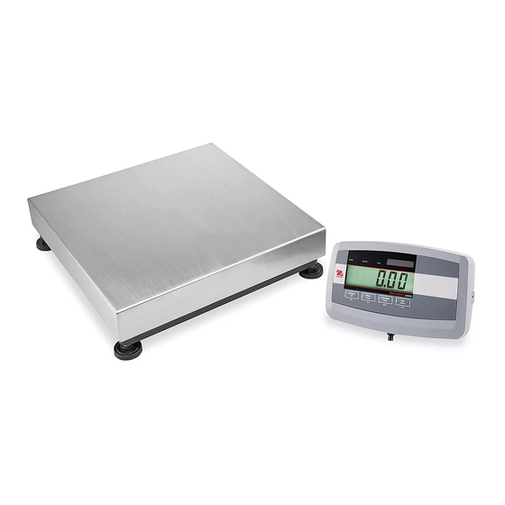
OHAUS DEFENDER
DIGITAL SCALE
CONTROL PANEL
1
2
CONTROL FUNCTIONS
#
BUTTON
ACTION
The five softkeys correspond to several icons at the bottom of the display area. These icons display for each softkey
1
function specifically available for configuration and operation of the mode.
Short press: if the terminal is off, power on the terminal; if the terminal is on, clear the data input.
On/CLR
2
O
Long press: Power off the terminal.
Short press: Send the current display value to the RS-232 port or option when properly enabled.
Print
3
Long Press: Change the current weighing unit. Press and hold the key to scroll through the list of enabled units.
Units
Release the key to switch to the unit selected.
Short press: Press the key to enter the library.
Library
4
Long press: Press and hold the key to change weighing modes. Press and hold the key to scroll through all weighing
Mode
modes. Release the key to switch to the mode selected.
Short press: Press the key to enter user profile.
User
5
Menu
Long Press: Press the key to enter user menu.
0
6
Short press: When the load on the pan is within the zero range, press the key to set the display to zero.
Short press: When a container is on the pan, press this key to store the weight of the container as the tare value.
T
Short press: Enter the known weight of a container using the numeric keypad, then press this key to establish preset tare value.
7
Short press: When a tare has been entered, empty the pan and press this key to clear the tare value.
Long press: If a preset tare has been entered, press this key to view the preset tare value.
PAGE 1 OF 33
5000
TM
OVERVIEW OF CONTROLS
Max
1
1
g
d=
g
123
2 17/ 8/15 11:37
g
>
<
0
ID
D
EFENDER
5000
On/CLR
Print
Library
User
O
Units
Mode
Menu
3
4
1-800-295-5510
uline.com
1
2
3
1
a
A
ABC
DEF
#./
4
6
0
5
GHI
JKL
MNO
.
7
8
9
PQRS
TUV
WXYZ
+/-
0
T
7
6
5
CONTROL PANEL PARTS
#
DESCRIPTION
9
1
Softkey Function Buttons
2
On/Clear Off Button
8
3
Print Units Button
4
Library Mode Button
5
User Menu Button
6
Function Mode Button
7
Tare Menu Button
8
Numeric Keypad
9
Input Modes Button
1219 IH-8105
Advertisement

Related Manuals for U-Line OHAUS DEFENDER 5000


Summary of Contents for U-Line OHAUS DEFENDER 5000
- Page 1 H-8105, H-8106 π 1-800-295-5510 H-8107 uline.com OHAUS DEFENDER 5000 DIGITAL SCALE OVERVIEW OF CONTROLS CONTROL PANEL CONTROL PANEL PARTS DESCRIPTION 2 17/ 8/15 11:37 Softkey Function Buttons > < On/Clear Off Button Print Units Button PQRS WXYZ Library Mode Button EFENDER 5000 User Menu Button...
- Page 2 OVERVIEW OF CONTROLS BUTTON ACTION To enter "2-9", press the numeric button in the middle of numeric input. To enter "A", press two times in the mode of uppercase input. To enter "Z", press five times WXYZ WXYZ in the mode of lowercase input. To enter "0", press the button in the mode of numeric input.
- Page 3 MENU STRUCTURE CONTINUED COMMUNICATION COMMUNICATION Baud Rate Assignment Parity Print Options Stop Bit Select Template Ethernet* Print Setup Handshake Edit Template Configuration Alt Print Command Edit String Alt Tare Command Reset Alt Zero Command MAC Address RS-232/2nd RS-232/ USB Device* Reset Network Assignment...
- Page 4 OPERATION MENU NAVIGATION User Long press the Menu button to enter main To enter the Main Menu, menu. Press the softkey press the button User corresponding to the Menu from any application Figure 2 icon to enter the home screen. (See Figure 1) Calibration submenu.
- Page 5 OPERATION CONTINUED 4. Press the softkey 3. Press the softkey corresponding to the corresponding to icon to initiate icon to initiate Span Calibration. Linearity Calibration. (See Figure 9) (See Figure 15) Figure 15 Figure 9 5. Place a calibration 4. Clear the pan and press the softkey corresponding mass of the specified to the icon.
- Page 6 OPERATION CONTINUED 2. Scroll to GEO Adjustment 3. Press the softkey using the softkey corresponding to the corresponding to the icon to edit GEO ▼ icon. (See Figure 21) value. Press the On/CLR button and enter desired Figure 22 Figure 21 value using keypad.
- Page 7 OPERATION CONTINUED TABLE OF GEO VALUES CONTINUED LATTITUDE GEO VALUE º º º º º º º º º º º º º º º º º º º º º º º º º º º º º º º...
- Page 8 OPERATION CONTINUED POWER ON ZERO When Dual interval is selected, the terminal functions with two intervals, each with its own capacity and Zero the balance at Power On. graduation. In addition to these parameters, the following two parameters are available: Off = disabled >|2|<...
- Page 9 OPERATION CONTINUED AUTO ZERO TRACKING NOTE: If the Security Switch is set to ON, the Capacity Unit, Range, Capacity, Graduation Set the automatic zero tracking functionality. and Power On Zero settings are not reset. = Disabled. READOUT MENU 0.5 division = Display will maintain zero until a change of 0.5 divisions per Enter this menu to customize display functionality.
- Page 10 OPERATION CONTINUED ADJUST CONTRAST RESET Set the contrast degree of the display. If Reset is selected and confirmed, all submenu values will return to default settings. For more details, see the table below. APPLICATION MODE OPTIONS AND DISCRETE I/O (bold is the default setting) Enable On, Off RESET...
- Page 11 OPERATION CONTINUED WEIGHING UNIT Least Significant Digit Set the graduation. Enter this menu to activate the desired units. Default settings are bold. Settings of 0.5, 1, 2, 5, 10 and 100 are available. NOTE: Due to national laws, the indicator may The custom unit’s name can be customized up to three not include some of the units of measure listed.
- Page 12 OPERATION CONTINUED PROJECT ID NOTE: If you select Lock All Keys, you will lose function of all keys. Set the Project identification. NOTE: If you select Lock Off Key, you will lose Refer to Menu Navigation to enter settings. function of the off key. SCALE ID AVAILABLE SETTINGS ITEM...
- Page 13 APPLICATIONS CONTINUED AUTO TARE Viewing the Accumulation Results 1. To view accumulation Set the automatic tare. results, press the Off: Auto tare is softkey corresponding turned off. to the icon. The (See Figure 27) Accumulate Result Figure 31 screen is displayed. (See Figure 31) Figure 27 2.
- Page 14 APPLICATIONS CONTINUED There are two methods to set the APW: NOTE: The I/Os will only work when the I/O Option Board has been installed. ENTERING A KNOWN APW The option I/O board provides two isolated inputs and Method 1 four dry-contact normally open relay outputs which can be used for simple process weighing.
- Page 15 APPLICATIONS CONTINUED APPLICATION SETUP Method 2 Press the softkey The Application can be customized for various user corresponding to the preferences. icon to enter Press the softkey the submenu for setting corresponding to the the number of pieces. Figure 47 icon to enter (See Figure 47) Configuration.
- Page 16 APPLICATIONS CONTINUED ACCUMULATION CHECK See Weighing section on page 13 for details about the Check is used to compare the weight or pieces of a Accumulation feature. sample against target limits. INPUT/OUTPUT (I/O) SETUP Press the button until the icon corresponding to Library Mode Check is displayed on the screen.
- Page 17 APPLICATIONS CONTINUED The Check Configurations are defined below. NOTE: Default settings are in bold. CONFIGURE ITEM OPTION DESCRIPTION Check Mode Check Weighing/Check Check weighing mode Counting Check counting mode Auto Tare Off/On/Accept Off: Auto tare is turned off. On: The first stable weight (>=5d) will be tared as a container automatically. Accept: If object weight is in the range of the Over and Under Limit you set, auto tare will be performed.
- Page 18 APPLICATIONS CONTINUED The Check Configurations are defined below. NOTE: Default settings are in bold. CONFIGURE ITEM OPTION DESCRIPTION Check Mode Weighing/Counting Weighing: Check weighing mode Counting: Check counting mode Auto Tare Off: Auto tare is turned off. Off/On/Accept On: The first stable weight (>=5d) will be tared as a container automatically. Accept: If object weight is in the range of the Over and Under Limit you set, auto tare will be performed.
- Page 19 APPLICATIONS CONTINUED 5. After completion of I/O's setup, press the softkey 3. Press the softkey corresponding to the icon to return to the main corresponding to the User Menu application screen. icon to save the value. Press the softkey PERCENT WEIGHING corresponding to the Figure 69 icon to exit submenu.
- Page 20 APPLICATIONS CONTINUED The Percent Configurations are defined below. NOTE: Defaults settings are in bold. CONFIGURE ITEM OPTION DESCRIPTION Auto Tare Off: Auto tare is turned off. Off/On On: The first stable weight (>=5d) will be tared as a container automatically. Accumulate Off/Manual/Automatic Off: The icon "Σ"...
- Page 21 APPLICATIONS CONTINUED The Dynamic Configurations are defined below. NOTE: Defaults settings are in bold. OPTION CONFIGURE ITEM DESCRIPTION Dynamic Mode Countdown/Continuous Countdown: There is a countdown time. Continuous: There is no countdown time. Operation Type Manual/ Manual: Semi-Automatic/ Place load on the pan. Automatic Press softkey to start dynamic weighing and countdown.
- Page 22 APPLICATIONS CONTINUED AVERAGE TIME SETUP INPUT/OUTPUT (I/O) SETUP There are two methods to set the averaging time. The The I/O's setup can be customized for user preferences. default average time is 10 seconds. The I/O's setup is defined below. NOTE: When time is set to 0, the first stable NOTE: Defaults settings are in bold.
- Page 23 SERIAL COMMUNICATION AND PRINTER SETUP Enter this menu to define external communication methods and to set printing parameters. Data may be output to either a printer or PC. RS-232/2 RS-232 Configuration NOTE: Factory default settings are shown in bold. OPTION COMMUNICATION Baud Rate 300, 600, 1,200, 2,400, 4,800, 9,600, 19,200, 38,400, 57,600...
- Page 24 SERIAL COMMUNICATION AND PRINTER SETUP CONTINUED HANDSHAKE AUTO ON ACCEPT Set the flow control method. If Auto On Accept is selected and weighing mode is Check, values will be printed when weight is accepted. NONE = no handshaking ACCEPT = Printing occurs each time the display is XON/XOFF = XON/XOFF handshaking within the Checkweigh accept range and stability criteria are met.
- Page 25 SERIAL COMMUNICATION AND PRINTER SETUP CONTINUED SELECT TEMPLATE EDIT TEMPLATE This submenu is used to define the format of the data This submenu is used to edit the current print template. output to a printer or computer. Each template supports up to 50 data fields to define the format of the data output.
- Page 26 SERIAL COMMUNICATION AND PRINTER SETUP CONTINUED INTERFACE COMMANDS The interface enables display and GMP data to be sent to a computer or printer. A computer can be used to control some functions of the indicator using the commands listed below. MT STANDARD CONTINUOUS OUTPUT A checksum character can be enabled or disabled with continuous output.
- Page 27 SERIAL COMMUNICATION AND PRINTER SETUP CONTINUED Status Byte B Bit Definitions Status Byte C Bit Definitions STATUS BITS FUNCTION BITS 2, 1 AND 0 Weight Description Bit 0 Gross = 0, Net = 1 Bit 1 lb or kg, selected by Status Byte B, Sign, Positive = 0, Negative = 1 bit 4 Bit 2...
- Page 28 SERIAL COMMUNICATION AND PRINTER SETUP CONTINUED MT-SICS Commands COMMAND FUNCTION LEVEL 0 Reset The scale. Inquiry of all available SICS commands. Inquiry of SICS level and SICS versions. Inquiry of scale data. Inquiry of scale software version. Inquiry of serial number. Send stable weight value.
- Page 29 SERIAL COMMUNICATION AND PRINTER SETUP CONTINUED RS-232 INTERFACE RS-232 (DB9) Pin Connections: Pin 2: Scale transmit line (TxD) Pin 3: Scale receive line (RxD) Pin 5: Ground signal (GND) Pin 7: Clear to send (hardware handshake) (CTS) Pin 8: Request to send (hardware handshake) (RTS) Use the built-in RS-232 port to connect to either a computer or a printer.
- Page 30 SERIAL COMMUNICATION AND PRINTER SETUP CONTINUED DEFINITIONS: Weight – Up to 11 characters, right justified – at immediate left of most significant character (if negative). Unit – Up to five characters, right justified. If the unit in the Print Content menu was set to off, the unit will be removed in the weight string and replaced by spaces.
- Page 31 BATTTERY INSTALLATION AND OPERATION NOTE: Battery is sold separately. See uline.com 5. Twist li-ion battery pack cable a half turn and for details. connect seven-pin connector from indicator to battery pack. Secure battery pack with one screw at CAUTION! Read all safety warnings before the location marked "Boss Screw 9."...
- Page 32 LEGAL FOR TRADE SEALING When the indicator is used in trade or a legally controlled application, it must be set up, verified and The local weights and measures official or authorized sealed in accordance with local weights and measures service agent must apply a security seal to prevent regulations.
- Page 33 TROUBLESHOOTING OPERATING ISSUE CAUSES RECOMMENDATIONS EEP Error EEPROM checksum error Corrupted EEPROM data. Unit will not Power cord not plugged in or connected. Check power cord connections. Make sure turn on. power cord is plugged in into power outlet. Power outlet not supplying electricity. Check power source.
Need help?
Do you have a question about the OHAUS DEFENDER 5000 and is the answer not in the manual?
Questions and answers