Inficon ULTRATEST UL3000 Fab Translation Of The Original Operating Instructions
Helium leak detector with sensor technology
Hide thumbs
Also See for ULTRATEST UL3000 Fab:
- Operating instructions manual (152 pages) ,
- Operating instructions manual (152 pages)

Related Manuals for Inficon ULTRATEST UL3000 Fab


Summary of Contents for Inficon ULTRATEST UL3000 Fab
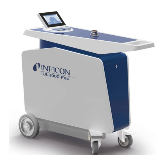
- Page 1 Translation of the original operating instructions UL3000 Fab, UL3000 Fab PLUS ™ Helium Leak Detector with ULTRATEST Sensor Technology Catalog No. 550-200, 550-250 From software version iina73en1-08-(1910) 1.41...
- Page 2 INFICON GmbH Bonner Strasse 498 50968 Cologne, Germany...
-
Page 3: Table Of Contents
INFICON Table of Contents Table of Contents 1 About these instructions ........................... 8 1.1 Target groups ............................ 8 1.2 Warnings.............................. 8 1.3 Definition of terms............................. 8 2 Safety ................................ 11 2.1 Intended use ............................ 11 2.2 Owner requirements .......................... 12 2.3 Duties of the operator .......................... 12 2.4 Dangers .............................. 12 3 Shipment, Transport, Storage ........................ 14... - Page 4 Table of Contents INFICON 4.4 Technical data ............................ 30 4.5 Factory settings ............................ 31 5 Installation .............................. 36 5.1 Setup .............................. 36 5.2 Connect the supplied accessories ...................... 39 5.3 Fastening bracket for sniffer line SL3000 (accessory, optional) ............. 44 5.4 Connecting to the power supply system .................... 45 5.5 Checking the operation of the device ..................... 45...
- Page 5 INFICON Table of Contents 6.3.2 Select gas ........................... 62 6.3.3 Setting setpoints ......................... 62 6.3.4 Activate vacuum ranges...................... 62 6.3.5 Set Auto Leak Test ........................ 63 6.3.5.1 Consider the background of the test chamber .............. 63 6.3.6 HYDRO•S (only UL3000 Fab PLUS) .................. 64 6.3.6.1...
- Page 6 Table of Contents INFICON 6.7.5 Call information on the assemblies ..................... 79 6.7.6 Call the energy data information .................... 80 6.7.7 Call information on the HYDRO•S (UL3000 Fab PLUS only) ............. 80 6.7.8 Call information on the SL3000 Sniffer line (UL3000 Fab PLUS only) ........ 80 6.8 Log................................ 80...
- Page 7 INFICON Table of Contents 10 Accessories and interfaces........................... 112 10.1 Accessories and spare parts ........................ 112 10.2 I/O module ............................ 117 10.2.1 Create a connection between the device and the I/O module .......... 117 10.2.2 Configuring analog outputs ....................... 117 10.2.3 Configure digital inputs ...................... 119 10.2.4 Configuring digital outputs ......................
-
Page 8: About These Instructions
1 | About these instructions INFICON 1 About these instructions This document applies to the software version stated on the title page. Product names may occur in the document, which are added for identification purposes only and belong to the respective owner of the rights. - Page 9 INFICON About these instructions | 1 Automatic tuning / mass setting This function adjusts the mass spectrometer so that a maximum leak rate indicator is achieved. In order to detect a maximum ion current with the ion detector, the control computer adjusts the voltage for accelerating the ions within the selected mass range accordingly.
- Page 10 1 | About these instructions INFICON Minimum detectable leak rate The minimum detectable leak rate which can be detected by the leak detector under ideal conditions (< 5 x 10 mbar l/s). MASSIVE After selecting the vacuum range "MASSIVE" gross leaks can now be measured from atmospheric pressure.
-
Page 11: Safety
INFICON Safety | 2 2 Safety 2.1 Intended use The device is a leak detector for detecting and measuring leaks in test objects. The device is suitable for leak detection using the vacuum method and the sniffer method. • Operate the device only according to this instruction manual. -
Page 12: Owner Requirements
2 | Safety INFICON 2.2 Owner requirements The following notes are for companies or any person who is responsible for the safety and effective use of the product by the user, employee or third party. Safety conscious operation • Operate the device only if it is in perfect technical condition and has no damage. - Page 13 INFICON Safety | 2 Dangers from electric There is a danger to life from the contact of conductive parts inside the device. power • Disconnect the device from the power supply prior to any installation and maintenance work. Make sure that the electric power supply cannot reconnected without authorization.
-
Page 14: Shipment, Transport, Storage
3 | Shipment, Transport, Storage INFICON 3 Shipment, Transport, Storage Scope of delivery Item Quantity UL3000 Fab or UL3000 Fab PLUS Exhaust hose adapter ISO-KF flange DN25 Hooks Power cable strain relief Screws M6 x 12 Lock washer Nuts Power supply cable EU... - Page 15 INFICON Shipment, Transport, Storage | 3 4) For inserting at the inlet flange, see “Inlet [} 27]“. 5) For fixing a corrugated tube between the inlet flange of the device and the test chamber or test object respectively". See "Connect the supplied accessories [} 39]".
-
Page 16: Description
4 | Description INFICON 4 Description 4.1 Function The device is a leak detector for detecting and measuring leaks in test objects. The device is suitable for leak detection using the vacuum method and the sniffer method. It uses the ULTRATEST sensor technology. - Page 17 INFICON Description | 4 If you have a UL3000 Fab PLUS, you can also connect the SL3000 sniffer line instead of the SL200 sniffer line. SL200 The vacuum connection of the sniffer line SL200 is connected to the upper side of the device on the inlet flange.
-
Page 18: Operation Mode "Auto Leak Test
4 | Description INFICON 4.2.3 Operation mode “Auto Leak Test” In this mode, you can perform tests on hermetically sealed components with automated processing. If the optional test chamber TC1000 is used, the test starts automatically when the cover is closed. - Page 19 INFICON Description | 4 Fig. 2: Front view with open flap. The remote control RC1000 shown here can be obtained as an option. UL3000-Fab-Operating-instructions-iina73en1-08-(1910) 19 / 140...
- Page 20 4 | Description INFICON Fig. 3: Back view. The picture shows standard accessories and optional accessories. 20 / 140 UL3000-Fab-Operating-instructions-iina73en1-08-(1910)
-
Page 21: Control Unit
INFICON Description | 4 4.3.2 Control unit Fig. 4: Control unit - front view The control unit consists of a touchscreen and a control panel with the buttons START, STOP and ZERO (background suppression) on the housing. See also "Assembly of the touchscreen [} 25]", see also "START button [} 22]". -
Page 22: Start Button
4 | Description INFICON USB 2.0 Interfaces For inserting a USB flash drive with update information "Updating the software [} 83]". For inserting a USB flash drive for copying measurement data, see "Measurement data [} 75]". For inserting a WiFi USB adapter for a WiFi connection, see "Operate leak detector via web... -
Page 23: Zero Button
INFICON Description | 4 Function Touchscreen Control panel Stop STOP button Vent Press the STOP button again and keep it pressed for approx. 2 seconds. (Prerequisite is the setting “ventilation mode” “manual”, see "Activate vacuum ranges [} 62]”.) 4.3.2.3 ZERO button •... -
Page 24: Meaning Of The Button Leds
4 | Description INFICON 4.3.2.4 Meaning of the button LEDs START button LED STOP button LED Meaning Flashing red No connection to the control unit Pulsing blue Pulsing blue Run up Green Standby vented (Vent valve open) Blue green Standby pumped out (Vent valve... -
Page 25: Assembly Of The Touchscreen
INFICON Description | 4 Status LED Meaning Green Measuring Yellow Measuring with warning not acknowledged Error 4.3.2.6 Assembly of the touchscreen The display is a touchscreen. The touchscreen responds to being touched lightly. To correctly select the chosen function, avoid strong pressure. - Page 26 4 | Description INFICON • Orange: Warning is active (navigation button diagnosis) Settings Operation Information Diagnosis Table 1: Navigation buttons Function buttons The buttons can appear in three different colors: • Gray: Function is disabled • Light blue: Function can be activated •...
-
Page 27: Vacuum Connections
INFICON Description | 4 4.3.3 Vacuum connections 4.3.3.1 Inlet The inlet is located on the upper part of the device. This is a DN 25 KF flange. If you select the vacuum leak test mode, connect the test object or the vacuum chamber to the flange. -
Page 28: Purge Gas Connection
4 | Description INFICON 4.3.3.3 Purge gas connection The connection for the purge gas is located on the lower side of the device, see "Connections for accessories and control signals [} 29]". This is a quick connection for hoses with an outside diameter of 8 mm. -
Page 29: Connections For Accessories And Control Signals
INFICON Description | 4 4.3.4 Connections for accessories and control signals SNIFFER (UL3000 Fab PLUS) Mains switch ACCESSORIES Connection for mains cable Venting connection REMOTE CONTROL Purge gas connection SERVICE Fig. 6: Connections for accessories and control signals SNIFFER (only UL3000... -
Page 30: Technical Data
4 | Description INFICON 4.4 Technical data Mechanical data UL3000 Fab, UL3000 Fab PLUS Dimensions (L × W × H) 1050 mm × 472 mm × 990 mm Weight 118 kg Inlet flange DN25 KF Display Display Color display with capacitive touchscreen Screen diagonal 7 inch Resolution 800 x 480 pixel Colors 16.7 M... -
Page 31: Factory Settings
INFICON Description | 4 UL3000 Fab, UL3000 Fab PLUS Minimum detectable leak rate sniffer < 5 x 10 mbar l/s mode Gas flow through sniffer line SL200 25 sccm Gas flow through sniffer line SL3000 160 sccm Measurement range 12 decades Sound pressure level in Standby <... - Page 32 4 | Description INFICON TMP rotation speed 1500 Hz (change not possible) Mass 4 (helium) Log on the IO1000 RS232 connection ASCII Analog output IO1000 channel 1 Leak rate mantissa Analog output IO1000 channel 2 Leak rate exponent Analog output IO1000 scaling 0.5 V / decade...
- Page 33 INFICON Description | 4 Inlet area offset mass 4 3.3 × 10 Analog output IO1000 upper exponent Pressure unit (display) mbar Leak rate unit vacuum operation (display) mbar l/s Leak rate unit sniffer operation (display) mbar l/s Sniffer line light alarm configuration (only...
- Page 34 4 | Description INFICON Local control Unlocked Clock style Analog Display background at standby Raise lower leak rate limit Minimum volume HYDRO•S (only UL3000 Fab PLUS) Deactivated Set maintenance interval Sniffer tip filter 1000 h Air filter 2500 h Set user Name...
- Page 35 INFICON Description | 4 Export format CSV en Enabled Export metadata WLAN Name (SSID) UL3xxx Network key INFICONUL Enable Method UL3000-Fab-Operating-instructions-iina73en1-08-(1910) 35 / 140...
-
Page 36: Installation
5 | Installation INFICON 5 Installation 5.1 Setup • So that measurement results are not falsified, use in an area that has a constant ambient temperature if possible. • In order not to block the exhaust opening on the lower part of the device, place the feet of the unit on a firm even surface. - Page 37 INFICON Installation | 5 CAUTION Danger of bruising extremities Feet can be rolled over and crushed. ► Keep feet away from the rollers. ► Do not pull the device. ► Hold the device by the provided handle only and slide it.
- Page 38 5 | Installation INFICON NOTICE Operating system can be attacked via USB or Ethernet The Linux operating system used in the leak detector is not updated automatically and can therefore contain security gaps. This vulnerability may be exploited through the Ethernet and USB interfaces of the leak detector to provide unauthorized access to the system.
-
Page 39: Connect The Supplied Accessories
INFICON Installation | 5 5.2 Connect the supplied accessories Install the “Hook for power line and sniffer line” Scope of delivery (amount): Hook (4), screw M6 x 12 (4), lock washer S6 (4) Required tools (supplied): Wrench T30 (Torx) • In order to be able to fix the mains cable and, if necessary, a sniffer line on the device, mount the hooks on the device as shown. - Page 40 5 | Installation INFICON Fig. 7: Hook at the instrument or at the optional bottle holder. Install the “Power line strain relief” Amount: Strain relief screw M6 x 12 lock washer S6 Required tools (supplied) Wrench T30 (Torx) • To avoid the risk of tripping mount the “strain relief power supply” at the device.
- Page 41 INFICON Installation | 5 1 Screw M6 x 12 2 Guard washer S6 3 Strain relief UL3000-Fab-Operating-instructions-iina73en1-08-(1910) 41 / 140...
- Page 42 5 | Installation INFICON Install the "Bracket for corrugated tube” (UL3000 Fab PLUS only) Scope of delivery (amount): Holder complete (1), screws M6 x 12 (3), lock washer S6 (3), self-tapping screws (2), edge protection made of PVC profile (1),...
- Page 43 INFICON Installation | 5 Fig. 8: The bracket for corrugated tube is mounted. Mounting the exhaust hose adapter on the device • To discharge gases through a DN25 exhaust hose, mount the KF flange DN25 exhaust hose adapter supplied in the exhaust port on the rear of the device.
-
Page 44: Fastening Bracket For Sniffer Line Sl3000 (Accessory, Optional)
5 | Installation INFICON 5.3 Fastening bracket for sniffer line SL3000 (accessory, optional) WARNING Risk of injury due to sniffer tip When stumbling, for example over lines, the sniffer tip can cause serious injuries, especially in eye contact. ► To avoid injury from the sniffer tip, align the sniffer tip in the bracket so that it points away from the operator. -
Page 45: Connecting To The Power Supply System
INFICON Installation | 5 5.4 Connecting to the power supply system WARNING Danger from electric shock Improperly grounded or fused products may be dangerous to life in case of a fault. The use of the device is not permitted without a connected protective conductor. - Page 46 5 | Installation INFICON ð The inlet is evacuated and then the measuring mode for the measured leak rate is shown. In case a test object was connected, you would start with spraying helium on the outside. In case you would like to suppress any possible existing background signals (helium background in the test object) press the ZERObutton.
-
Page 47: Operation
INFICON Operation | 6 6 Operation 6.1 Switching on ► In order to switch on the device, press the power switch. ð When delivered, the device shows the window "Standby" after run-up. Fig. 9: Window "Standby" Starting the measurement Calibrating Purge Vent 6.2 Basic settings... -
Page 48: User Profile Settings
6 | Operation INFICON > Setup > General > Date and time Set up. Save Alternatively, press in the upper window bar and make your settings. 6.2.3 User profile settings 6.2.3.1 Overview of Rights Groups The rights of auser depend upon which group he belongs to. -
Page 49: Modify Personal Settings
INFICON Operation | 6 The login window opens. , to modify a user profile. The window "User profile" opens. , to delete a user profile. A confirmation screen appears. After selecting some tools, the “User profile” window opens. If this window opens, enter a user name, change it, or keep it as required. -
Page 50: Switch Off Automatic Login
6 | Operation INFICON 2 Logging off from the device [} 86] 6.2.4 Switch off Automatic Login Factory setting Login: Supervisor PIN: 1111 Language: English As per factory settings, after switching on the device the user "Supervisor" automatically logs in and the measurement screen is called. This default user also has the permissions of the group "Supervisor". -
Page 51: Changing The Presentation Of The Line Graph
INFICON Operation | 6 To switch between the different diagram presentation press on the lower left of the measurement screen, see "Assembly of the touchscreen [} 25]”. You can select between the following presentations: • Line graph • Bar graph • Circle graph You can further configure the different diagram presentations. -
Page 52: Changing The Presentation Of The Bar Graph
6 | Operation INFICON In the field "Time axis" select the length of the time axis "30", "60", "90", "120" or "240" seconds. If the option "Autoscale" is not active, select "Lower diagram limit" in the field the desired decade. -
Page 53: Changing The Presentation Of The Circle Graph
INFICON Operation | 6 6.2.6.3 Changing the presentation of the circle graph Fig. 12: Presentation of the circle graph ü Operator or Supervisor rights > Display > Circle graph If you want to fix the number of displayed decades in the pie chart, under "Decades“... - Page 54 6 | Operation INFICON ð The internal background is created from the remaining gas, which has not yet been pumped out. Very clean systems show a background in the range of 1 x mbar l/s. Under normal conditions there is a background of 1 x 10 mbar l/s or 1x10 mbar l/s.
-
Page 55: Result Display Of The Auto Leak Test
INFICON Operation | 6 6.2.7 Result display of the Auto Leak Test Supervisor 1 "Passed" or "Failed" as the result of the last test under "Part number". Test failed if the leak rate exceeds the setpoint. 2 Actual test time, within set limits, see “Set Auto Leak Test [} 63]“... -
Page 56: Change Audio Settings
6 | Operation INFICON If necessary change the units of the "Leak rate unit vacuum", the "Leak rate unit sniff" and the "Pressure unit". ð The option “Equal to display “ is activated according to the factory settings so that the units for the interface can be shown exactly as the units of the device. -
Page 57: Change The Protection Settings
INFICON Operation | 6 ð "Leak rate proportional": The frequency of the audible signal is proportional to the bar graph display or diagram height. The frequency range is 300 Hz to 3300 Hz. ð "PINPOINT": The sound of the acoustic signal changes its frequency within a specific range of leak rates. -
Page 58: Set Maintenance Interval "Filter Sniffer Tip" Or "Air Filter
6 | Operation INFICON Note: The following setting does not apply if the vacuum range "Massive" is switched on. See also “Activate vacuum ranges [} 62]“: To change the maximum evacuation time after a gross leak is detected, enter the desired time in seconds under "Max. evacuation time gross leak". -
Page 59: Activate Or Deactivate Maintenance Requests
INFICON Operation | 6 ð Enter a value of your choice in hours for the "Air filter" or press the adjacent "Default value" button (2500 hours). Save After performing a maintenance, you should reset the desired period until the next maintenance. -
Page 60: Extending Or Reducing Operation Options
6 | Operation INFICON If the option "calibration request" is active, you will get a calibration request subsequently in the following cases: • The period of the device is longer than 30 minutes and the temperature deviation compared to the last calibration is larger than 5 Kelvin. -
Page 61: Settings For The Measurements
INFICON Operation | 6 Use Favorites: ► Press the icon with your permission and then the “Favorites” button or choose alternatively ► > User accounts > Favorites ð The Favorites window with 9 buttons is displayed. Assigned buttons can be used to quickly call up desired functions. -
Page 62: Select Gas
6 | Operation INFICON 6.3.2 Select gas DANGER Danger from a Hydrogen explosion Hydrogen can explode in combination with oxygen. The allowable composition of venal gas mixtures can be read in the safety data sheets of the respective manufacturers. ► Ensure that the share of hydrogen does not exceed the described concentration. -
Page 63: Set Auto Leak Test
INFICON Operation | 6 At least one range must be activated. ü Operator or Supervisor rights > Setup > Measurement > Vacuum > Vacuum ranges Activate the desired vacuum range under "Vacuum range". Save 6.3.5 Set Auto Leak Test Please take note of the information on the operation mode "Auto Leak Test" and the notes on measuring. -
Page 64: Hydro•S (Only Ul3000 Fab Plus)
6 | Operation INFICON ð The chamber is evacuated 3 times and vented. ð After cleansing, the current helium background is measured. ð The new values of the measured background are automatically stored and subtracted from the results of future measurements. -
Page 65: Setting The Machine Factor
INFICON Operation | 6 ü ZERO is switched off. After switching on HYDRO•S the ZERO can be used again. See "Set and use the function ZERO [} 67]". ► Switch HYDRO•S by pressing on or off on the measurement screen. By means of Stop you always switch off HYDRO•S. -
Page 66: Set External Calibration Leak
6 | Operation INFICON 6.3.8 Set external calibration leak To use an external calibration leak for calibration, enter the leak rate of the calibration leak. ü Operator or Supervisor rights > Setup > Measurement > Calibration leak Adopt the printed value and the associated unit from the calibration leak or certificate. -
Page 67: Set And Use The Function Zero
INFICON Operation | 6 6.3.10 Set and use the function ZERO Why should I use To be able to clearly measure small leakages the function ZERO should be used. ZERO? With each leak detection there is a "Background signal" (see "Definition of terms [} 8]") that disrupts the search or the measurement of leakages. -
Page 68: Vent, Purge, Regenerate
6 | Operation INFICON “Vacuum” operation When you press the ZERO button, the current leak rate value is set to the lower mode, “HYDRO•S” is display limit. switched on, effect on Note: The ZERO button should not be pressed when there is a rapidly falling... -
Page 69: Change Leak Rate Filter
INFICON Operation | 6 If necessary activate the option "Automatic purge". ð If you switch off the automatic purging, you can switch purging on or off in the standby window by pressing Save Regeneration It may happen that too much helium has entered the interior of the device and no accurate measurements are possible (helium contamination). - Page 70 6 | Operation INFICON After activating "Background suppression" the internal background and selectably also the background in the inlet area is deducted from the leak rate. This happens after pressing the START button automatically. ü Supervisor - rights > Setup > Measurement > ZERO and filter Make your selection in the field “Background suppression“...
-
Page 71: Determine The Background Of The Inlet Area
INFICON Operation | 6 6.3.13.1 Determine the background of the inlet area This function determines the value of the internal Helium background. If "Zero and Filter" are shown in the window under background suppression with value "Inlet area" selected, this value is then deducted from the measured signal whenSTART is pressed. -
Page 72: Calibrating
6 | Operation INFICON ð You can change the following settings, to view the preset values see “Factory settings [} 31]“. “Pressure SL200 capillary blocked“ (lower limit) “Pressure SL200 capillary broken“ (upper limit) “Pressure SL3000 capillary blocked“ (lower limit, UL3000 Fab PLUS only) “Pressure SL3000 capillary broken“... -
Page 73: Check Calibration
INFICON Operation | 6 Mount the calibration leak on the inlet of the device. > Setup > Measurement > Calibration leak Adjust the leak rate of the calibration leak used, see also “Set external calibration leak [} 66]”. Place the device in the state "Standby" or "Measure". -
Page 74: Measuring
6 | Operation INFICON 6.4 Measuring ü The inlet flange on the upper side of the device is prepared for the pending measurement. Your test specimen or the SL200 sniffer line is normally connected there. ü Alternatively, the sniffer line SL3000 is connected to the back of the device (optional). -
Page 75: Measuring Helium Ambient Concentration (Ul3000 Fab Plus Only)
INFICON Operation | 6 6.5 Measuring helium ambient concentration (UL3000 Fab PLUS only) The natural content of helium in the ambient air is about 5.2 ppm. You can examine the ambient air for an increased helium content (helium contamination) to determine the appropriate time for further measurements. -
Page 76: Display Measurement Cycles
6 | Operation INFICON > Setup > Data recording To record immediately after starting a measurement, activate the option "Enabled". Note: Data recording occurs during the measurements, i.e. while the measurement screen is displayed. See also "Display measurement cycles [} 76]". - Page 77 INFICON Operation | 6 A data interface was implemented for this purpose (REST interface). This interface responds to requests on port 3000 when valid parameters are transmitted with data in the requested format. ü A network connection has been established between the leak detector on one side and the PC or Tablet on the other side.
-
Page 78: Measurement Data Database: Information
6 | Operation INFICON Parameter Name Description Options For example Format The data format of the json, csv_en, csv_de f=json export Standard: csv_en f=csv_en Scope Scope of the data. With mr: Meta and d=mr or without metadata measured values m: Meta only... -
Page 79: Call The Latest Information To The Current Calibration Value
INFICON Operation | 6 ► > Measurements > Temperature ð Different temperature values are displayed. ► > Measurements > Runtime ð The current runtime information is displayed. 6.7.2 Call the latest information to the current calibration value ► > Calibration 6.7.3 Information on connected accessories... -
Page 80: Call The Energy Data Information
6 | Operation INFICON ► > Assemblies > MSB ► > Assemblies > Backing pump 6.7.6 Call the energy data information Diverse measure supply voltages, electrical power and temperatures are shown. ► > Energy > Voltage (1) ð In this window the first part of the information to the voltage is shown. -
Page 81: Call Calibration Log
INFICON Operation | 6 6.8.2 Call calibration log The entries are for the entire period of use of the device. If there are more than approx. 20 entries always the oldest entry is deleted. ► > Logs > Calibrations 6.8.3 Call maintenance log ►... -
Page 82: Exporting Or Importing Sets Of Parameters
6 | Operation INFICON > Sets of parameters > Manage sets of parameters ð Sets of parameters already created will be displayed as a list. If the values of a saved set of parameters match the actual settings of the device 100 %, a green dot will be displayed. -
Page 83: Updating The Software
INFICON Operation | 6 To export all sets of parameters to a USB flash drive (formatted in FAT32) if needed, press below the list. To import all sets of parameters from a USB flash drive into the device, press below the list. -
Page 84: Update The Software In Expert Mode
6 | Operation INFICON NOTICE Data loss due to an aborted connection ► Do not switch off the device and do not remove the USB flash drive while the software is being updated. ü Supervisor - rights Copy the file into the main directory of a FAT32 formatted USB flash drive. -
Page 85: Resetting To Factory Settings
INFICON Operation | 6 Fig. 13: The most important components of the vacuum diagram in UL3000 Fab devices 1 Mass spectrometer 6 Sniffer line 2 Internal calibration leak 7 Pressure measuring point for flow monitoring 3 Inlet flange 8 Fore pump... -
Page 86: Logging Off From The Device
6 | Operation INFICON ð To reset the device to the factory settings, press both buttons one after the other. 6.13 Logging off from the device Press your name, which is displayed in the upper left corner of the display, or select >... -
Page 87: Warning And Error Messages
INFICON Warning and error messages | 7 7 Warning and error messages During operation, the display shows information that helps you operate the instrument. Measurement values are displayed along with current unit modes, operating instructions as well as warnings and error messages. The instrument is equipped with extensive self-diagnostic functions. - Page 88 7 | Warning and error messages INFICON Type Notification Possible sources of Remedy error W104 One EEPROM parameter A new parameter was • Confirm the warning message has been initialized introduced by a • Check that the message does not appear...
- Page 89 INFICON Warning and error messages | 7 Type Notification Possible sources of Remedy error W110 Real-time clock was reset! The real-time clock has • Enter the correct date and time Please enter date and time not been set • Check that the message does not appear...
- Page 90 7 | Warning and error messages INFICON Type Notification Possible sources of Remedy error W132 Sniffer line type (XL) not A sniffer line type (XL) • Replace the sniffer line with a sniffer line allowed cannot be used with type supported by the device...
- Page 91 INFICON Warning and error messages | 7 Type Notification Possible sources of Remedy error W208 24V fan supply voltage out Malfunction of a fan • Contact customer service of range Short circuit or • Contact customer service overload in the 24V fan...
- Page 92 7 | Warning and error messages INFICON Type Notification Possible sources of Remedy error W222 Internal voltage 24V_IO The module connected • Use another module, if possible voltage out of range to LD connector is defective The cable connected to •...
- Page 93 INFICON Warning and error messages | 7 Type Notification Possible sources of Remedy error W300 Anode voltage too low Short circuit of the • Contact customer service anode voltage VI-Board or MSB • Contact customer service defective W301 Anode voltage too high MSB defective •...
- Page 94 7 | Warning and error messages INFICON Type Notification Possible sources of Remedy error E312 Cathodes broken Both cathodes • Contact customer service defective Connection to cathode • Contact customer service broken VI-Board or MSB • Contact customer service defective...
- Page 95 INFICON Warning and error messages | 7 Type Notification Possible sources of Remedy error W401 TMP warning message Unhandled error • Contact customer service message from the TMP E402 No communication with TMP cable defective or • Contact customer service...
- Page 96 7 | Warning and error messages INFICON Type Notification Possible sources of Remedy error E423 TMP pressure rise Inrush of air into TMP • Contact customer service W452 No communication with Backing pump control • Contact customer service backing pump...
- Page 97 INFICON Warning and error messages | 7 Type Notification Possible sources of Remedy error E521 Pressure rise, anode voltage Pressure rise at • Contact customer service collapsed pressure sensor p2 and anode voltage collapsed W522 Pressure rise, emission Pressure rise at •...
- Page 98 7 | Warning and error messages INFICON Type Notification Possible sources of Remedy error W580 Maximum evacuation time Gross leak at test • Check the tightness of the connection until 100 mbar exceeded object or the between the leak detector and the test...
- Page 99 INFICON Warning and error messages | 7 Type Notification Possible sources of Remedy error W640 Auto Leak Test: Too many Leak rate setpoint 1 • Check and change the leak rate setpoint consecutive tests failed does not match to the...
- Page 100 7 | Warning and error messages INFICON Type Notification Possible sources of Remedy error W904 Maintenance: Sniffer tip filter Maintenance interval • Contact customer service for sniffer tip filter exceeded W910 Maintenance: Backing pump Maintenance interval • Contact customer service...
-
Page 101: Cleaning And Maintenance
INFICON Cleaning and maintenance | 8 8 Cleaning and maintenance All cleaning and maintenance work described here must be carried out without opening the side walls! WARNING Life threatening hazard from electric shock High voltages are inside the device. Touching parts where electrical voltage is present can result in death. -
Page 102: Replacement Of The Filter Mat On The Bottom Of The Device
8 | Cleaning and maintenance INFICON Remove the used air filter from the plastic grid and insert a new one. Refit the plastic grid together with the new air filter. 8.3 Replacement of the filter mat on the bottom of... - Page 103 INFICON Cleaning and maintenance | 8 Loosen the screws, which fix the filter mat on the metal sheet. Replace the filter mat. Secure the filter mat with the screws, insert the metal sheet and fix it with the knurled screw.
-
Page 104: Replacing The Sl200 Sniffer Line Filter
8 | Cleaning and maintenance INFICON 8.4 Replacing the SL200 sniffer line filter Structure of the sniffer Fig. 14: Sniffer tip 1 Capillary filter (plastic; standard) 4 Cross-head screws 2 Felt pads 5 Sinter filter 3 Capillary filter (metal with gasket;... -
Page 105: Replacing The Sl3000 Sniffer Line Filter
INFICON Cleaning and maintenance | 8 • Unscrew the capillary filter and replace it with a new one. Do not forget the gasket for the metal version! Check or replace the Switch off the leak detector or disconnect the sniffer line from the device. - Page 106 8 | Cleaning and maintenance INFICON Table 3: Capillary filter 1 Sniffer line end 4 Plastic capillary filter 2 cone seal 5 Water conservation tip 3 Metal capillary filter Capillary filter and water conservation tip are screwed onto the sniffer line end. The filter inserts are inserted and lie in front of a small metal grill that is also inserted.
-
Page 107: Creating Screenshots
INFICON Cleaning and maintenance | 8 If you have activated the display of maintenance requests, set the maintenance interval to the desired new period. Also see "Activate or deactivate maintenance requests [} 59] " and "Set maintenance interval "Filter sniffer tip" or "Air filter"... -
Page 108: Sending For Repair Or Maintenance
Maintenance inside the device should only be performed by the manufacturer. We recommend having the device serviced every 4000 hours or annually. You can send in your device to INFICON so it can be maintained or repaired. For further details see "Sending in the device [} 110]”. -
Page 109: Maintenance Plan
Explanation of the maintenance plan: • I Service level I Customer • II Service level II Customer with technical training • III Service level III Authorized INFICON service technician • X Carry out maintenance as per operating hours or duration • X No time limit only operating hours •... -
Page 110: Decommissioning The Measuring Instrument
9 | Decommissioning the measuring instrument INFICON 9 Decommissioning the measuring instrument 9.1 Sending in the device WARNING Danger due to harmful substances Contaminated devices could endanger the health. The contamination declaration serves to protect all persons who come into contact with the device. - Page 111 INFICON Decommissioning the measuring instrument | 9 UL3000-Fab-Operating-instructions-iina73en1-08-(1910) 111 / 140...
- Page 112 10 | Accessories and interfaces INFICON 10 Accessories and interfaces 10.1 Accessories and spare parts The parts listed below can additionally be ordered: Bus module BM1000 PROFIBUS 560-315 BM1000 PROFINET IO 560-316 BM1000 DeviceNet 560-317 BM1000 EtherNet/IP 560-318 I/O module...
- Page 113 INFICON Accessories and interfaces | 10 Capillary filter, metal(1 unit) 12217 Capillary Filter SL 300, set 5 pieces(Plastic capillary filter) 20003501 Intern Filter For SL3XX (5/PKG)(Sinter-filter with O-Ring) 20003500 Water conservation tip (1 unit) 122 46 SL3000 bracket 551-203 Remote control RC1000...
- Page 114 10 | Accessories and interfaces INFICON Helium bottle holder The Helium bottle holder allows the transport of a Helium supply with a spray gun along with the leak detector. Only small to medium size bottles (max. 10 I, 200 bar) fit without compromising the stability of the device.
- Page 115 INFICON Accessories and interfaces | 10 Fig. 20: The transmitter can be attached to a free spot with the supplied Velcro tape. Search for the wireless remote control from the leak detector If you have misplaced the RC1000WL wireless remote control, you can trigger acoustic signals from the UL3000 Fab or the UL3000 Fab PLUS from this remote control.
- Page 116 10 | Accessories and interfaces INFICON Fig. 21: Test chamber TC1000 116 / 140 UL3000-Fab-Operating-instructions-iina73en1-08-(1910)
-
Page 117: Accessories And Interfaces | 10
ü Supervisor - rights Connect the INFICON I/O module with a data cable to the LD socket on the rear of the device, see "Connections for accessories and control signals [} 29]". > Setup > Accessories > Device selection Select the "IO module". - Page 118 10 | Accessories and interfaces INFICON Pressure p1 / Pressure 1 ... 10 V; 0.5 V / decade; logarithmic 1 V = 1 x 10 mbar Leak rate mantissa 1 ... 10 V; linear; in the Useful only if the other analog output is assigned selected unit "Leak rate exponent".
-
Page 119: Configure Digital Inputs
INFICON Accessories and interfaces | 10 10.2.3 Configure digital inputs These inputs can be used to operate the device with a programmable logic controller (PLC). The digital inputs PLC-IN 1 ... The available functions can be assigned in any way necessary to the 10 I/O module. -
Page 120: Configuring Digital Outputs
10 | Accessories and interfaces INFICON 10.2.4 Configuring digital outputs The digital outputs PLC-OUT 1 ... The available functions can be assigned in any way necessary to the 8 I/O module. ü Supervisor - rights > Setup > Accessories > I/O module > Digital outputs configuration Select the desired "Digital output". -
Page 121: Setting Up The I/O Module Protocol
INFICON Accessories and interfaces | 10 Function State: Description Cathode 2 closed: Cathode 2 is active open: Cathode 1 is active Measuring closed: Measuring (ZERO is possible, all setpoint outputs switch depending on the leak rate.) open: Standby or emission disabled (ZERO is not possible, all setpoint outputs will return "Leak rate threshold value exceeded".) -
Page 122: Bus Module
To establish the connection between the leak detector and the bus module, proceed as follows: Switch off the leak detector. Connect the INFICON bus module via a data cable to the LD socket of the device, see “Connections for accessories and control signals [} 29]“. Switch on the leak detector. -
Page 123: Network
INFICON Accessories and interfaces | 10 10.4 Network 10.4.1 Operate leak detector via web browser (LAN) NOTICE Operating system can be attacked via USB or Ethernet The Linux operating system used in the leak testing is not updated automatically and can therefore contain security gaps. -
Page 124: Setting The Lan Connection In The Pc Or Tablet
10 | Accessories and interfaces INFICON 10.4.1.2 Setting the LAN connection in the PC or Tablet LAN connection - quick start If you have performed the steps described here once, it is sufficient to enter the IP address for many devices in case of repetition. -
Page 125: Operate Leak Detector Via Web Browser (Wireless Lan)
INFICON Accessories and interfaces | 10 10.4.2 Operate leak detector via web browser (wireless LAN) NOTICE Operating system can be attacked via USB or Ethernet The Linux operating system used in the leak testing is not updated automatically and can therefore contain security gaps. This vulnerability may be exploited through the Ethernet and USB interfaces of the leak testing to provide unauthorized access to the system. -
Page 126: Setting The Wireless Lan Connection In The Pc Or Tablet
10 | Accessories and interfaces INFICON To set-up that the device supports the WLAN connection activate the option "Enable Wireless LAN". In the field “WiFi Name (SSID)” enter the desired network name and in the field “WiFi Network key” the desired Network key. -
Page 127: Allow Client Access
INFICON Accessories and interfaces | 10 10.4.2.3 Allow client access ü Supervisor - rights > Setup > Network > Client access To allow the leak detector to be operated by PC or Tablet, activate the "Client Access" option. ð If the option "Client Access" is not activated, the leak detector cannot be operated via PC or Tablet. -
Page 128: Appendix
11 | Appendix INFICON 11 Appendix 11.1 Menu path Pressing the navigation button brings you back to the measurement display regardless of whether you were previously in a menu or sub-menu. 11.1.1 Diagnosis > Confirmed warnings ð Can only be seen when active. - Page 129 INFICON Appendix | 11 > Display > Line graph > Audio > User accounts > Log off > User accounts > Manage Auto Login > User accounts > Manage user accounts > User accounts > Change own PIN > User accounts > Change own language >...
-
Page 130: Information
11 | Appendix INFICON > Setup > Maintenance counter > Setup > Accessories > Setup > Accessories > Bus module > Setup > Accessories > Device selection > Setup > Accessories > I/O module > Setup > Accessories > I/O module > I/O module protocol >... - Page 131 INFICON Appendix | 11 > Measurements > Runtime > Measurements > Leak rate and pressure > Measurements > Temperature > Sniffer line > Accessories > Accessories > Bus module > Accessories > I/O module UL3000-Fab-Operating-instructions-iina73en1-08-(1910) 131 / 140...
-
Page 132: Ce Declaration Of Conformity
11 | Appendix INFICON 11.2 CE Declaration of Conformity 132 / 140 UL3000-Fab-Operating-instructions-iina73en1-08-(1910) - Page 133 INFICON Appendix | 11 UL3000-Fab-Operating-instructions-iina73en1-08-(1910) 133 / 140...
- Page 134 11 | Appendix INFICON 134 / 140 UL3000-Fab-Operating-instructions-iina73en1-08-(1910)
-
Page 135: Index
INFICON Index Index Display temperature value 79 Access controls 48 Auto Leak Test Evacuation time gross leak 58 Operation mode (Definition) 18 Evacuation time measurements 58 Result display 55 Select operation mode 61 Settings 63 Automated login Factory settings 31 Switch off 50... - Page 136 Index INFICON Sniffer line SL3000 113 Software Operating options 60 Update basic unit 83 Operation User interface update 83 PC, Tablet 126 Supervisor 48, 50 Operation mode "Sniffing" 16, 61 Switch OFF 86 Operation mode "Vacuum" 16, 61 Switching on 47...
- Page 137 INFICON Index ZERO 74 Button 23 Factory setting 67 UL3000-Fab-Operating-instructions-iina73en1-08-(1910) 137 / 140...
- Page 138 Index INFICON 138 / 140 UL3000-Fab-Operating-instructions-iina73en1-08-(1910)
Need help?
Do you have a question about the ULTRATEST UL3000 Fab and is the answer not in the manual?
Questions and answers