
Subscribe to Our Youtube Channel
Related Manuals for Inficon Sentrac Strix Edition


Summary of Contents for Inficon Sentrac Strix Edition
- Page 1 Operating Instructions ® ™ Sentrac Strix Edition Hydrogen Leak Detector Type number: SEN.122.162, SEN.122.163 From software version ninb65en1-01-(2010) 2.01.01...
- Page 2 INFICON AB Wahlbecksgatan 25 SE-582 13 Linköping Sweden...
-
Page 3: Table Of Contents
INFICON Table of Contents Table of Contents 1 General Information............................ 7 1.1 About this Document .......................... 7 1.1.1 Related Manuals ........................... 7 1.1.2 Document History ......................... 7 1.2 Introduction to the Instrument ........................ 7 1.2.1 Intended Use.......................... 7 1.2.2 Available Models........................... 8 1.3 Password Menu ............................ 8 1.4 Warnings.............................. 8... - Page 4 Table of Contents INFICON 8.1 Instrument Display .......................... 23 8.1.1 Menu Navigation ......................... 23 8.1.2 Menu Buttons.......................... 25 8.1.3 Navigation and Other Buttons..................... 25 8.2 Passwords and Menu Overview ...................... 26 9 Operating the Instrument.......................... 29 9.1 Preparation ............................. 29 9.1.1 Conditions for Leak Detection..................... 29 9.2 Battery Operation............................ 30...
- Page 5 INFICON Table of Contents 12.1.1 Run Time ............................ 41 12.1.2 Calibration........................... 41 12.1.3 I•Guide ............................ 41 12.2 Export/Import ............................ 41 12.2.1 Export............................ 41 12.2.2 Import............................ 42 12.3 Settings Overview........................... 42 12.4 I/O ................................ 42 12.5 Show Password ............................ 42 12.6 About .............................. 42 13 Diagnosis................................ 43 13.1 Warning .............................. 43...
- Page 6 19 Spare Parts and Accessories ......................... 69 19.1 Spare Parts............................. 69 19.2 Accessories ............................ 70 20 Support from INFICON ........................... 71 20.1 How to Contact INFICON ........................ 71 20.2 Returning Components to INFICON ....................... 71 21 EU Declaration of Conformity ......................... 72 22 Disposing of the Instrument.......................... 73 23 Appendix................................. 74...
-
Page 7: General Information
INFICON General Information | 1 1 General Information Read this Manual carefully before putting your instrument into service. When reading, pay particular attention to the WARNINGS, CAUTIONS and NOTICES found throughout the text. 1.1 About this Document The purpose of this manual is to: •... -
Page 8: Available Models
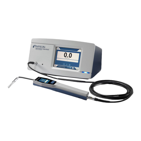
1 | General Information INFICON 1.2.2 Available Models Fig. 1: Available Models Sensistor Sentrac Part no. Sentrac Strix edition, desktop model For stationary use 590-830 Sentrac Strix edition, portable model 12 hours operating time on 590-840 batteries 1.3 Password Menu All menus except the service menu are available when no basic, intermediate, or advance password is set. - Page 9 INFICON General Information | 1 NOTICE Hazardous situation resulting in damage to property or the environment Sensistor_Sentrac_Strix_Operating_Manual_ninb65en1-01-(2010) 9 / 80...
-
Page 10: Equipment And Storage
2 | Equipment and Storage INFICON 2 Equipment and Storage When receiving the equipment, check that it has not been damaged during transport. 2.1 Supplied Equipment Desktop Model Pos. Part Part no. Instrument Unit Desktop Model 590-905 Strix Hand Probe... -
Page 11: Supplied Equipment Portable Model
INFICON Equipment and Storage | 2 2.2 Supplied Equipment Portable Model Pos. Part Part no. Instrument Unit Portable Model 590-915 Strix Hand Probe 590-730 Probe Cable (3 m) 590-161 Battery Charger 591-795 Sample Kit Probe Tip 591-799 Sensor Key 598-461... -
Page 12: Peripheral Equipment
2 | Equipment and Storage INFICON 2.3 Peripheral Equipment Pos. Part Tracer gas Compressed Air Tracer Gas Filler Two-Step Gas Regulator Calibration Leak with Certificate Calibration Gas with Certificate Compressed Air Filter For more information, see Spare Parts. 12 / 80... -
Page 13: Storage Environment Sensistor Sentrac
INFICON Equipment and Storage | 2 2.4 Storage Environment Sensistor Sentrac Desktop Model (590-830) Temperature: 0°C - 45°C (32°F - 113°F) Humidity Range: 10% to 75% RH (non-condensing) Portable Model (590-840) Temperature: 0°C - 45°C (32°F - 113°F) Humidity Range:... -
Page 14: Instrument Description
3 | Instrument Description INFICON 3 Instrument Description The instrument is manually controlled by the touchscreen menu system. The screen also shows results and sequence graphically and in plain text. 3.1 Front View Pos. Port/Interface Probe Connector Port Earphone Jack... -
Page 15: Rear View
INFICON Instrument Description | 3 3.2 Rear View Pos. Port/Interface Connect Not used SD Card Slot SD Card USB 2.0 To a host (for example PC) I/O-connector RS232, PLC I/O and signals. Probe Connector Port Probe Power Input (Desktop Model) -
Page 16: Labels
3 | Instrument Description INFICON 3.3 Labels At the rear side of the instrument, a label indicates the electrical specifications of the instrument and its serial number. Pos. Labels Device Plate Desktop Model Device Plate Portable Mode Manufacturing Year Label Connections Label SEN. -
Page 17: Hand Probe
INFICON Hand Probe | 4 4 Hand Probe NOTICE Connection and disconnection of the sensor cable must be done with power off. Sensor can be damaged if power is on. The Hand Probe is a no-flow probe. Gas sensing takes place in the replaceable sensor located in the tip of the probe. -
Page 18: Calibration
4 | Hand Probe INFICON For more information see Spare Parts. 4.2 Calibration The probe must be calibrated for optimal accuracy. Make sure it is calibrated before using it to measure gas concentration or leak rate value. For more information see Calibration. -
Page 19: System Examples
INFICON System Examples | 5 5 System Examples 5.1 Desktop Model Pos. Description Sensistor Sentrac Desktop Model Compressed Air Tracer Gas Tracer Gas Filler e. g. TGF11 Strix Hand Probe Test Object Evacuation and Gas Filling Sensistor_Sentrac_Strix_Operating_Manual_ninb65en1-01-(2010) 19 / 80... -
Page 20: Portable Model
5 | System Examples INFICON 5.2 Portable Model Pos. Description Sensistor Sentrac Desktop Model Test Object Strix Hand Probe 20 / 80 Sensistor_Sentrac_Strix_Operating_Manual_ninb65en1-01-(2010) -
Page 21: Setup
6.2 Connect the Instrument 1. Connect the Hand Probe to the instrument using the probe cable. If you have purchased another type of probe than the Strix Hand Probe, contact INFICON for help. Adaptation equipment between probe and instrument may be required. -
Page 22: Settings
7 | Settings INFICON 7 Settings 7.1 Probe Settings ► To set the probe button functions, click Settings > Probe > Functions. The lamp options can also be set here. 7.2 General Settings ► To set brightness, sound, date and language, click Settings > General. -
Page 23: Menu System
8 Menu System 8.1 Instrument Display 8.1.1 Menu Navigation NOTICE Do not cause any damage by sharp objects on the instrument touchscreen. INFICON recommends using the fingertip for touching the touchscreen. Icon colors Grey Shows top screen in current menu. clickable... - Page 24 8 | Menu System INFICON Settings Screen CALIBRATION RECIPE LOCATING MODE GENERAL MEASURING MODE COMMUNICATION PASSWORD PROBE Settings Info Screen STATISTICS I/Os SHOW PASSWORDS EXPORT / IMPORT ABOUT SETTINGS OVERVIEW Info Diagnosis Screen WARNINGS FACTORY DEFAULT SERVICE SCREEN Warnings 24 / 80...
-
Page 25: Menu Buttons
INFICON Menu System | 8 8.1.2 Menu Buttons Icon Description Icon Description Settings Audio Operation Mute Info Sensitivity Diagnosis Calibration Measuring Mode Recipe Locating Mode I•Guide Combined Mode 8.1.3 Navigation and Other Buttons Icon Description Icon Description Start Save Stop, Close... -
Page 26: Passwords And Menu Overview
8 | Menu System INFICON 8.2 Passwords and Menu Overview There are three different levels of access, indicated by the respective user icon below. Icon Description Basic. The password can be set to access basic level Basic users can operate the instrument, but not calibrate or change settings. - Page 27 INFICON Menu System | 8 Menu Menu Tabs Password Basic Inter- Advance Level 1 Level 2 mediate I•Guide Settings Calibration Calibrate Setup 1 Setup 2 Interval Info Locating Mode Sensitivity Misc Measuring Mode Unit Reject Misc I•Guide Probe Functions Recipe...
- Page 28 8 | Menu System INFICON Menu Menu Tabs Password Basic Inter- Advance Level 1 Level 2 mediate Show password About Diagnosis Warnings Warnings Service screen Signals Locating Graph Debug Settings Test Board Reset Settings Factory Default Calibration 28 / 80...
-
Page 29: Operating The Instrument
INFICON Operating the Instrument | 9 9 Operating the Instrument 9.1 Preparation NOTICE When the instrument is put into operation the sensor withstands temporary exposure to hydrogen concentrations up to 100%. Avoid long exposures to high concentrations. During normal use, the blue LED light of the instrument should be steady. -
Page 30: Battery Operation
9 | Operating the Instrument INFICON 9.2 Battery Operation The Sensistor Sentrac Portable Model is designed for mobile operation. The battery charger will not restart automatically when the battery runs low if you leave battery charger connected. For stationary operation you must do the following: 1. -
Page 31: How To Detect Leaks
INFICON Operating the Instrument | 9 2. Set up a calibration leak which corresponds to the smallest leak you want to detect. For more information see Calibration. 3. Put the probe close to the calibration leak and note the approximate reaction you get (no reaction, small, medium, high, full scale) within the first few seconds. -
Page 32: Measuring Leaks
9 | Operating the Instrument INFICON Default unit in Measuring Mode is cc/s. To set it to other units click Settings > Measuring Mode. The period during which the measured value is displayed can be adjusted in the Measuring Mode Settings menu. Click Settings > Measuring Mode. -
Page 33: To Quantify Leaks
INFICON Operating the Instrument | 9 2. Move the Hand Probe close to and along the pressurized test object. Move the probe on the possible places where there may be leaks. 3. When a leak is found and the highest signal is found, move the probe away from the leak and back again for verification. - Page 34 9 | Operating the Instrument INFICON To use I•Guide If a fixed number of measurement points is used, then measure according to the following steps: 1. Press the probe button, or start button on the screen, to begin the first measurement.
-
Page 35: Recipes
INFICON Recipes | 10 10 Recipes A recipe is a collection of settings suited for a particular test setup. This is used for having different settings for different test objects. Calibration settings are not saved in the recipe. A calibration leak or calibration gas is normally used to calibrate the instrument. -
Page 36: Select An Existing Recipe
10 | Recipes INFICON 3. Click Settings > Recipe to enter the Recipe Setup menu. 4. Modify your recipe. 5. Click Save actual setup to save your recipe. 10.2.3 Select an Existing Recipe 1. Click Settings > Recipe to enter the Recipe Setup menu. -
Page 37: Calibration
• Calibration gas: Available at gas suppliers and has a known concentration of hydrogen (10 ppm hydrogen in synthetic air is recommended). • Calibration leak: Available at INFICON and has a fixed leak rate (mbar l/s or g/y). Both methods take less than 2 minutes to perform. -
Page 38: How To Calibrate
For more information see Spare Parts and Accessories. 11.2 How to Calibrate INFICON support two types of Calibration Leak. The one with large leaks must be connected to tracer gas pressure to work. The small leak is connected to a small fillable gas container. -
Page 39: Calibration Procedure
INFICON Calibration | 11 Example, Calibration Leak: Calibration Leak Rate is 4.2E-05 mbar l/s (95% N - 5% H Calibration Unit = mbar l/s Calibration Value = 4.2E-05 Calibration Leak Gas = 95% N - 5% H Example, Calibration Gas: Calibration Gas containing 10 ppm Hydrogen in synthetic air. - Page 40 11 | Calibration INFICON 7. Continue the calibration routine until you can save the calibration. NOTICE Wait at least 15 seconds between each calibration. If the calibration is not saved, the instrument will revert to the previous value. When changing setup or probe you will need to repeat the exposure 2-3 times to get Calibration OK.
-
Page 41: Info
INFICON Info | 12 12 Info 12.1 Statistics 12.1.1 Run Time ► To see the current operation time, click Info > Statistics > Run Time. Two runtime counters can be reset and used for specific needs. The two timers are also reset when a reset is performed on the instrument. -
Page 42: Import
12 | Info INFICON 12.2.2 Import All useful settings, including recipes, can be imported from an SD-card. 1. Insert the SD-card with the backup into the SD-card holder 2. Click Info > Export/Import > Import 3. In Settings, click on the backup from SD-button The previously exported settings, including any recipe, is imported to the instrument. -
Page 43: Diagnosis
INFICON Diagnosis | 13 13 Diagnosis 13.1 Warning ► To see a list of all occurred warnings, click Diagnosis > Warnings. This list can only be reset by authorized service personnel. 13.2 Service Screen This screen is used for servicing and repair. -
Page 44: Serial Communication
14 | Serial Communication INFICON 14 Serial Communication USB/RS232 Types of USB/RS232 • Read Parameter Read parameters who have impact of the commands measurement • Write Parameter Write parameters who have impact of the measurement • Read Device Setup Read data about the instrument and device •... - Page 45 INFICON Serial Communication | 14 RS232 set up Baud rate: 115200 (Default) Data: Priority: None Stop bit: Read and Write Parameters Parameter Read Write Sequence Answer Sequence value/text of Data of Data LANGUAGE rP01\n Language: [text] wP01 [value]\n 0 = EN...
- Page 46 14 | Serial Communication INFICON Parameter Read Write Sequence Answer Sequence value/text of Data of Data LEAK_GAS_VISCOSITY rP07\n Leak Gas Viscosity wP07 [value]\n Enable when Leak gas (µPas): [value] not set to: 95%N /5%H , Air, He, , R123a, R22,...
- Page 47 INFICON Serial Communication | 14 Parameter Read Write Sequence Answer Sequence value/text of Data of Data MEAS_GAS rP21\n Displayed Gas: wP21 [text]\n If write 95%N - 5%H [text] Air, He, N , R123a, R22, R290, R404a, R407c, R410, R600a, R1234yf automatic converting is enabled.
- Page 48 14 | Serial Communication INFICON Parameter Read Write Sequence Answer Sequence value/text of Data of Data MEAS_READY_PULSE rP32\n Measuring Audio wP32 [text]\n 0 = On Ready Pulse: [text] 1 = Off MEAS_DIGITS rP33\n 3 digits in measure wP33 [text]\n 0 = On...
- Page 49 INFICON Serial Communication | 14 Parameter Read Write Sequence Answer Sequence value/text of Data of Data SCREEN_TIMEOUT rP43\n Screen saver: wP43 [text]\n 0 = Off [text] 1 = 5 s 2 = 30 s 3 = 1 min 4 = 2 min...
- Page 50 14 | Serial Communication INFICON Read and Write Device Setup Setup Read Write Explanation Sequence Answer Sequence value/text of Data of Data Read/write rDis\n [S/N] wDis [text]\n Max 8 characters instrument serial Read rDiv\n [SW ver. No.] X.XX.XX instrument S/W...
- Page 51 INFICON Serial Communication | 14 Execute Commands Execute command Sequence of Value/text Explanation Data Bitmap Dump cEBD\n Save a bitmap of Sentrac screen on SD-card inserted into Sensistor Sentrac. File name: [time].bmp Operation Mode cEom 1 … 3 1 = Localization...
- Page 52 14 | Serial Communication INFICON Command File Command File Sequence of Data Answer Explanation Delete file cFdl SENTRAC.LOG\n File deleted Delete saved measuring data on SD- card and send it as a text file. (“No data to delete/Data delete error” if no saved data) (“SD-card not inserted”...
-
Page 53: Troubleshooting
INFICON Troubleshooting | 15 15 Troubleshooting 15.1 Faulty Symptoms Fault Symptom Fault Measures No sound in Detection Sound set low. Click the speaker icon to Mode and Analysis Mode. increase the volume Broken speaker or speaker Send in for repair. -
Page 54: Warning Messages
15 | Troubleshooting INFICON 15.2 Warning Messages Message Indicators Message in the Code menu warning list Probe not Blue LED flashing. (None) (None) connected. SD-card not Orange measure (None) (None) inserted. window at screen. Battery discharged. Orange measure (None) (None) Recharge battery. -
Page 55: Maintenance Instructions
Electrical shock Do not open the instrument needlessly! Service of this equipment may only be carried out by service organizations authorized for this purpose by INFICON. Changing the battery is the only time when opening the instrument is needed and allowed. -
Page 56: Changing Probe Tip Filter
16 | Maintenance Instructions INFICON 16.2 Changing Probe Tip Filter Part Part no. Qty. Consumables Probe Tip Filter 590-310 Disassemble ► Remove the Probe Filter (A) using a needle. Assemble ► Install the new Probe Filter. 16.3 Changing Probe Protection Cap Part Part no. -
Page 57: Changing Probe Sensor
INFICON Maintenance Instructions | 16 Disassemble 1. Attach the supplied Sensor Key at the bottom of the Probe Tip Protection Cap (A) and pull with one finger on each side of the probe tip. 2. Remove the Protection Cap (A). -
Page 58: Changing The Battery (Portable Model)
Electrical shock Do not open the instrument needlessly! Service of this equipment may only be carried out by service organizations authorized for this purpose by INFICON. Changing the battery is the only time when opening the instrument is needed and allowed. - Page 59 INFICON Maintenance Instructions | 16 Changing the Battery 1. Remove the two screws (C) holding the power switch panel. 2. Remove the four screws (A) holding the Battery (B). 3. Remove the Battery (B). 4. Remove the Battery cabling from the power switch panel and main PCB.
- Page 60 16 | Maintenance Instructions INFICON Assembling the Cover 1. Reinstall the cover (C). Make sure that the lock washer on the Probe Connection Port (LEMO connector on main PCB) is still present. Important for proper grounding. Make sure that no cables are pinched between the cover and the chassis.
-
Page 61: Software Update
INFICON Maintenance Instructions | 16 16.6 Software Update Download the update software to a computer. Locate the downloaded file. Double click on Setup.exe. ð If an older version of the software is already installed, it must be removed. Follow the given directions. -
Page 62: Service
If the instrument suffers external damage, it must be checked and repaired by a service organization authorized by INFICON. In case of required service or repair, contact nearest INFICON service center. Please visit www.inficon.com for further information. 62 / 80... -
Page 63: Technical Data
INFICON Technical Data | 18 18 Technical Data Electrical Data Power supply 100-240 V (ac), 50/60 Hz, 2 A Internal rechargeable battery (Portable Li-Ion, 14.8 V / 65 Wh (4400 mAh) Model) Physical Data Lowest detectable leak rate 0.1 ppm H... -
Page 64: Interfaces And Connectors
18 | Technical Data INFICON 18.1 Interfaces and Connectors CAUTION The outputs will be destroyed Outputs are not relay types. Do not connect external drive source such as 24 VDC or 100/230 VAC. All ports below are the same for both Portable and Desktop Model, except for where otherwise stated. - Page 65 INFICON Technical Data | 18 Signal Specification Function RS232: TxD (DTE transmit See note Serial communication data) RS232: RxD (DTE receive See note Serial communication data) RS232: RTS See note Serial communication (Request to send, issued by DTE) RS232: CTS...
- Page 66 18 | Technical Data INFICON Signal Specification Function Audio line out AC-coupled Output External Speaker Output is unbalanced Line_OUT- is connected to GND Line_OUT+ carries analog audio symmetrically to GND Output voltage swing, min = - 1.65 V Output voltage swing, max = +1.65 V Output impedance = 160 Ω...
- Page 67 INFICON Technical Data | 18 Notes OUT Note on RS-232 communication: This system is a DCE device with only RXD, TXD and GND. Remaining RS-232 signals are not implemented. A DB9-to-DB25 adapter can be used: then connect the DB25 male to this system (DCE) and connect the DB9 female to the terminal device (DTE).
-
Page 68: Probe Connector Port
18 | Technical Data INFICON • Gas Signal • Not Ready or Gas Signal • Error (summary error) Inputs: • Unused • Start (I•Guide) • Stop (I•Guide) • Locating Signal Zeroing • External Alert 18.1.4 Probe Connector Port Cable: C21 Probe Cable 18.1.5 Power Input (Desktop Model) -
Page 69: Spare Parts And Accessories
INFICON Spare Parts and Accessories | 19 19 Spare Parts and Accessories 19.1 Spare Parts Pos. Part Type Description Part no. Hand Probe Strix With a rigid neck 590-730 C21 Probe Cable 590-161 590-175 590-165 Mains Cord 591-146 Desktop Model... -
Page 70: Accessories
19 | Spare Parts and Accessories INFICON 19.2 Accessories Pos. Part Type Description Part no. Tracer Gas Filler TGF11 Contact INFICON for further information Calibration Leak For calibration and Contact INFICON function tests of probes for further information Calibration Gas... -
Page 71: Support From Inficon
Customer Service Representative. You must obtain a Return Material Authorization (RMA) number from the Customer Service Representative. If you deliver a package to INFICON without an RMA number, your package will be held and you will be contacted. This will result in delays in servicing your instrument. -
Page 72: Eu Declaration Of Conformity
21 | EU Declaration of Conformity INFICON 21 EU Declaration of Conformity 72 / 80 Sensistor_Sentrac_Strix_Operating_Manual_ninb65en1-01-(2010) -
Page 73: Disposing Of The Instrument
According to EU legislation, this product must be recovered for separation of materials and may not be disposed of as unsorted municipal waste. If you wish you can return this INFICON product to the manufacturer for recovery. The manufacturer has the right to refuse taking back products that are inadequately packed and thereby presents safety and/or health risks to the staff. -
Page 74: Parameter Index
23 | Appendix INFICON 23 Appendix 23.1 Parameter index Parameter Range Factory Default Language English Operation Mode Combined Mode Unit cc/s Calibration Value >0 <1E+30 2.20E-5 Calibration Sampling Time (s) >2 Leak Gas Viscosity (uPas) >0 <1E+30 18.2 Density (g/l) >0 <1E+30... - Page 75 INFICON Appendix | 23 Parameter Range Factory Default Measuring Audio Ready Pulse 3 digits in measure value I•Guide Mode I•Guide Measuring Time (s) min 0.5 s max 1000 s I•Guide Positions 1-25 Probe Button Function No function Probe Lamp Recipes active...
-
Page 76: Index
51 installation Communication desktop model 19 Settings 22 portable model 20 connection Instrument instrument to hand probe 21 Rear View 15 Contact INFICON 71 Cover Assembling 60 Labels 16 Remove 58 Leak Detection 33 Leak Detection 31, 33 Diagnosis Detection 31... - Page 77 INFICON Index Measuring Export 41 Leak 32 Import 42 Menu Modify 35 Navigation 23 35 Screens 23, 24 Overview 35 Menu Overview 26, 27 Select 36 Mode Returning Components 71 Locating 30 RS232 22 Measurement 32 Measuring 33 Service 62 settings 42...
- Page 78 Index INFICON 78 / 80 Sensistor_Sentrac_Strix_Operating_Manual_ninb65en1-01-(2010)
Need help?
Do you have a question about the Sentrac Strix Edition and is the answer not in the manual?
Questions and answers