
Related Manuals for Inficon HLD5000


Summary of Contents for Inficon HLD5000
- Page 1 T E C H N I C A L H A N D B O O K kina40e1-g (1007) Catalog No. 510-010 510-015 510-016 510-017 510-018 from software version V 4.1 HLD5000 Refrigerant Sniffer Leak Detector...
-
Page 3: Table Of Contents
Working with the HLD5000 Controls and their Function 3.3.1 Overview of the Controls and Display Components 3.3.2 Mains Switch 3.3.3 LED Display of the HLD5000 3.3.4 LC Display 3.3.5 Probe HLD5000 Settings (Menu Structure) Description of the Menu "Program” 4.1.1 TRIGGER 4.1.2... - Page 4 INFO Description of the Menu Item INFO Menu Item STANDBY Selecting the gas type Calibration 4.5.1 Checking the Calibration 4-10 4.5.2 Calibrating the HLD5000 with the COOL-Check 4-10 4.5.3 Calibrated leak (COOL-Check) 4-11 Shutting Down 4-11 Switching probes 4-11 Messages...
- Page 5 Failure to observe the following precautions could result in serious personal injury: Warning The HLD5000 must not be operated while standing in water or under running or dripping water. The same applies to all other kinds of liquids. The HLD5000 should only be used indoors.
- Page 6 Failure to observe the following precautions could result in damage to the equipment: Caution Avoid contact of the HLD5000 with bases, acids or solvents and also avoid exposure to extreme climatic conditions. Caution Before loosening the connecting nut, you must switch off the HLD5000 first. When exchanging the sniffer tip make sure that no dust or particles of dirt enter into the opening.
- Page 7 Under all circumstances memorize the new PIN! The PIN can only be reset by INFICON’s service organization. Caution Before exchanging any of the sniffer line filters please switch off the HLD5000. When replacing filters please make sure that no particles enter into the intake opening.
- Page 8 General Safety Precautions...
-
Page 9: General
Warning The HLD5000 must not be operated while standing in water or under running or dripping water. The same applies to all other kinds of liquids. The HLD5000 should only be used indoors. -
Page 10: Technical Data
Technical Data 1.2.1 Physical Data Lowest trigger level setting For single gas probes 1.0 g/a (0.04 oz/yr) For universal Smart probe 0.5 g/a (0.02 oz/yr) Maximum trigger level setting 50 g/a (1.76 oz/yr) Measurement range For single gas probes 0 - 100 g/a (3.57 oz/yr) For universal Smart probe 0 - 300 g/a (10.7 oz/yr) Detectable refrigerants... -
Page 11: Ordering Information
Cat. No. 510-017 HLD5000 for R600a/R290 Cat. No. 510-018 Supplied Equipment The HLD5000 is delivered ready for operation. Before installing the HLD5000 please read Chapter 1.6. The following items have been included with the leak detector: • Probe with line •... -
Page 12: Replacement Parts / Accessories
1.3.1 Replacement parts / Accessories Sniffer tips Cat.-No. Probe tip, 100 mm long 511-021 Probe tip, 400 mm long, flexible 511-024 Extension line, 400 mm long (flexible) for the 511-020 probe tip (20 pieces) Extension (flexible) for sniffer tip, angled by 45° (20 pieces) 511-029 Water protection tip 511-025... -
Page 13: Service
Service If the HLD5000 is returned to INFICON, indicate whether the leak detector is free of substances damaging to health or whether it is contaminated. If it is contaminated also indicate the nature of the hazard. INFICON will return any leak detector without a "Declaration of Contamination”... -
Page 14: Service Centers
Kiriat Ono Fax: +972 35 34 25 89 INFICON LTD Phone: +86.10.6590.0164 Japan reach.japan@inficon.com Beijing Fax: +86.10.6590.0521 INFICON LTD Phone: +86.20.8723.6889 INFICON Co. Ltd. Phone: +81.45.471.3396 Guangzhou Fax: +86.20.8723.6003 Yokohama Fax: +81.45.471.3387 INFICON LTD Phone: +86.21.6209.3094 Shanghai Fax: +86.21.6295.2852 Czech Republic filip.lisec@inficon.com... - Page 15 Fax: +49 221 347 42221 Poland kamola@vakpol.com Taiwan Susan.Chang@inficon.com VAK-POL & GAZ Sp. zo.o Phone: +48 60 23 15 212 INFICON Company Limited Phone: +886.3.5525.828 Pulawy Fax: +48 60 23 15 212 Chupei City, HsinChu Hsien Fax: +886.3.5525.829 Portugal ana.correia@zickermann.pt Tunisia leakdetection.service@inficon.com...
-
Page 16: Notes On How To Read This Manual
Menu item A single menu line. Standby mode Resting status of the HLD5000. The pump and valve system is off in this mode. Personal password number so as to be able to prevent unauthorised changes to leak detector settings. -
Page 17: Installation
Installation 1.6.1 Unpacking Unpack the HLD5000 immediately after delivery, even if it is to be installed later on. Examine the shipping container for any external damage. Completely remove the packaging materials. Notice Retain the shipping container and the packaging materials in the event of complaints about damage. -
Page 18: Rs232 Interface
1.6.5 RS232 Interface The HLD5000 is equipped with a RS232 interface which is located on the rear of the main unit under the mains connection (Fig. 1-2). This interface is of the DCE type (Data Communications Equipment) and allows the connection of a PC for monitoring and data logging. -
Page 19: Use Of The Flexible Sniffer Tip
1.6.6.2 Use of the flexible sniffer tip In addition to the rigid sniffer tip included with the HLD5000, also a 400 mm long flexible tip (Cat. No. 511-024) may be used. By correspondingly bending the flexible tip, areas which are hard to access can be reached. - Page 20 If, even so, liquid has been sucked into the sensor system, let the HLD5000 run for about 10 minutes (not in the standby mode) to pump out the liquid from the sensor system via the supply pump in the main unit.
-
Page 21: Principle Of Operation
Infrared light from a corresponding source is made to pass through a cell through which also the gas taken in by the HLD5000 flows. This light is filtered so that only light having a specific wavelength is allowed to pass on to an infrared light detector. -
Page 22: Hld5000 Overview
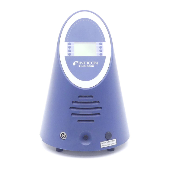
HLD5000 Overview Fig. 2-2 Overview Pos. Description Pos. Description Calibration port RS232 Interface Connection for the probe’s line Mount Keys for operating the menu Built-in calibrated leak LC display (not for SF version) LED display Air filter Mains switch Probe... -
Page 23: Operating The Hld5000
(factory default: g/a) is indicated on the display (Fig. 3-2/4). Moreover, the type of probe (detectable gas) to which the HLD5000 has been set up is indicated on the sticker on the probe. The main unit is usable for all refrigerants, the detectable refrigerant is determined by the probe. -
Page 24: Working With The Hld5000
In this case, please use the flexible sniffer tip extension (Cat. no. 511-020) which is delivered with the HLD5000. For this application the extension tip can be cut down to 100 mm (4 in.) length for easier handling. (see Chapter 1.6.6.3) Depending on the measurement mode (see Chapter 4.1) the test should be repeated... -
Page 25: Controls And Their Function
Controls and their Function 3.3.1 Overview of the Controls and Display Components The controls and display components of the HLD5000, with the exception of the button and the LED at the probe, are all located at the main unit (Fig. - Page 26 Gas type of probe Info button Trigger Display of leak rate Standby button Menu button • The left lower button opens the main menu. • The right lower button opens the info page HLD5000 to sleep mode. Operating the HLD5000...
-
Page 27: Probe
3-3/3). The LED indicates the following operating modes: Operating condition Description off: HLD5000 not ready to measure green (steady): normal operating mode / no errors green, flashing: error / measurement not possible or accuracy of the measurements can not be guaranteed. - Page 28 The button is provided to select the different testing modes, see Chapter and to calibrate the HLD5000, see Chapter 4.5. The eye (see Fig. 3-3/4) serves the purpose of hanging the handle, for example, when not being used.
-
Page 29: Hld5000 Settings (Menu Structure)
HLD5000 Settings (Menu Structure) Fig. 4-1 Structure of the menu Via the menu, the HLD5000 may be adapted to the specific operating conditions or requirements in each case. The menu opens by pressing the key. PROGRAM Operating sets the HLD5000 into the standby mode in which the valve and STANDBY pump are switched off. -
Page 30: Trigger
Smart probe has for the different gases. However, the trigger value will stay the same. When choosing a user definable gas the HLD5000 can either be calibrated externally or a calibration factor can be entered to enable a calibration with the built-in calibrated leak. -
Page 31: Volume
BUTTON The HLD5000 permits the entry of different configurations as to the operation of the button in the probe so as to allow different working and test methods to be implemented: "OFF"... -
Page 32: Options
If by accident the display has been set too bright or too dark so that it can not be read anymore, this may be changed as follows: Switch off the HLD5000 and switch it on again. During the warm up phase hold the menu key 3 or 7 pressed (see Fig. - Page 33 A time span ranging between 1 and 15 minutes may be entered. If the HLD5000 is not used for a period of time longer than the one set up here, the leak detector will thereafter revert automatically to the standby mode.
-
Page 34: Cal
4.1.5 Through this menu item the HLD5000 may be calibrated with an external test leak. The SF and CO version of the HLD5000 can only be calibrated using an external calibrated leak. When pushing the „ “ button the following information appears in the display: “Sniff external test leak“, the appointed leak rate and the type of... - Page 35 Supply voltage for the infrared light source in the probe (U light) • Current flow through the infrared light source in the probe (I light) • Probe test voltage to monitor the voltage supply (U probe) HLD5000 Settings (Menu Structure)
-
Page 36: Description Of The Menu Item Info
Indicates the current date as day, month and year. TIME Indicates the current time as hours, minutes and seconds. NEXT CALIBRATION Indicates how long it will be (hours and minutes) until the reminder to calibrate will be displayed. HLD5000 Settings (Menu Structure) -
Page 37: Menu Item Standby
”) during the first 25 seconds, the HLD5000 can only be AUTO STANDBY reactivated by pressing any key. After this time, operating any key on the HLD5000 or moving the handle will reset the leak detector back to the measurement mode. Selecting the gas type For selective, single gas probes (Cat. -
Page 38: Checking The Calibration
Calibrating the HLD5000 with the COOL-Check To calibrate the HLD5000, press the button on the probe and insert the sniffer tip into the calibration port at the front of the main unit. The HLD5000 will then start the calibration process automatically. During the calibration process it is not necessary to keep the button on the probe pressed. -
Page 39: Calibrated Leak (Cool-Check)
Replacement leaks should not be purchased in advance of their need as they have a limited lifetime. Shutting Down The HLD5000 may be switched off at any time by operating the mains switch independently of the operating mode it is in. All parameters are saved when the HLD5000 is powered down. - Page 40 4-12 HLD5000 Settings (Menu Structure)
-
Page 41: Messages
Errors are events which force an interruption to the measurement sequence and which the HLD5000 is not capable of remedying on its own. Errors are displayed in plain text on the display. The error sound is a two-tone sound. - Page 42 Change Cool Check Sensor sensitivity too low! Optical cell is contaminated with water Depending on the quantity of water let run the HLD5000 from 1 minute to 2 hours Light barrier dirty Dust has accumulated in the test leak Turn off HLD5000. Blow out the test leak opening and is interrupting the light opening with compressed air.
-
Page 43: Maintenance
HLD5000 from being contaminated all filters should be exchanged preventatively. There are three filters in the HLD5000, two within the sniffer tip filtering the air intake through the sniffer line and one air filter at the bottom of the housing. - Page 44 Caution Before exchanging any of the sniffer line filters please switch off the HLD5000. When replacing filters please make sure that no particles enter into the intake opening. The fine filters at the probe tip are firmly built into the filter holder. To replace the filter...
-
Page 45: Cleaning The Opening Of The Calibrated Leak
6.2.3 Cleaning The housing of the HLD5000 is made of plastic. Therefore to clean the housing use cleaning only agents which are recommended to clean plastic surfaces (for example mild household cleaning agents). Do not use any solvents which attack plastic materials. - Page 46 Switch off the HLD5000 on and run a new calibration after about 5 minutes. A residual amount of refrigerant might be left under pressure (more than 5 bar) in the canister of the empty leak standard.
- Page 47 This form can be downloaded Copies: from our website. Original for addressee - 1 copy for accompanying documents - 1 copy for file of sender INFICON GmbH Bonner Str. 498,50968 Cologne, Germany zisa01e1-a Tel: +49 221 3474 2222 Fax: +49 221 3474 2221 www.inficon.com leakdetection.service@inficon.com...
- Page 48 Fig. 6-2 Declaration of Conformity Maintenance...
- Page 49 Appendix alarm gas type alarm, audible gases baud rate installation 1-10 BUTTON interface 1-10 button interface description 4-11 calibrated leak language calibrated leak, external leak test 4-10 calibration – – calibration factor LED, green 4-10 checking the calibration LED, yellow control component level (ALT) 4-10...
- Page 50 1-10 RS232 sensitivity Settings HLD5000 shipping container 1-10 sniffer tip solvent standby 4-10 test leak, internal trigger – trigger level setting unit volume warm-up phase water protection tip Weight Appendix...
-
Page 51: Appendix
Appendix... - Page 52 INFICON GmbH, Bonner Strasse 498, D-50968 Cologne, Germany Phone: +49 (0)221 347-40 Fax: +49 (0)221 347-41429 E-mail: leakdetection@inficon.com UNITED STATES TAIWAN JAPAN KOREA SINGAPORE GERMANY FRANCE UNITED KINGDOM HONG KONG Vi s i t o ur w eb s i t e f o r c on ta c t i nf o rma t i on an d o t he r s al es of f i c e s w or l dwi de . w w w. i n fi c o n . com...
Need help?
Do you have a question about the HLD5000 and is the answer not in the manual?
Questions and answers