Table of Contents
Advertisement
Quick Links
-
Safety Instructions....................................................................................
1.1 Safety Precautions................................................................................................
-
Instructions..............................................................................................
2.1 Dimensions..........................................................................................................
2.2 Part List For Box A...............................................................................................
2.3 Part List For Box C...............................................................................................
2.4 Components in the Hardware Kit..........................................................................
2.5 Components on the Product..................................................................................
-
Assembly Instructions...............................................................................
Before Assembly...........................................................................................................
STEP 1 Support Arm, Bottle Holder, and Rear Support Installation...........................
STEP 2 Weight Plate and Cable Installation..............................................................
STEP 3 Apply the Weight Stack Sticker.....................................................................
STEP 4 Install the Top Handle Frame.......................................................................
STEP 5 Side Handle Installation...............................................................................
STEP 6 Installation....................................................................................................
STEP 7 Weight Stack back Cover Installation..........................................................
STEP 8 Front Top Cover Installation.........................................................................
STEP 9 Rear Top Cover Installation..........................................................................
STEP 10 Stack Fork Operation.................................................................................
-
Operating Instructions.............................................................................
4.1 Operating the Product..........................................................................................
4.2 Testing..................................................................................................................
4.3 Maintenance.........................................................................................................
TABLE OF CONTENTS
1
1
2
2
3
4
4
5
6
6
7
11
21
23
24
25
26
28
29
30
31
31
32
33
Advertisement
Table of Contents

Subscribe to Our Youtube Channel
Related Manuals for SportsArt Fitness DF-107


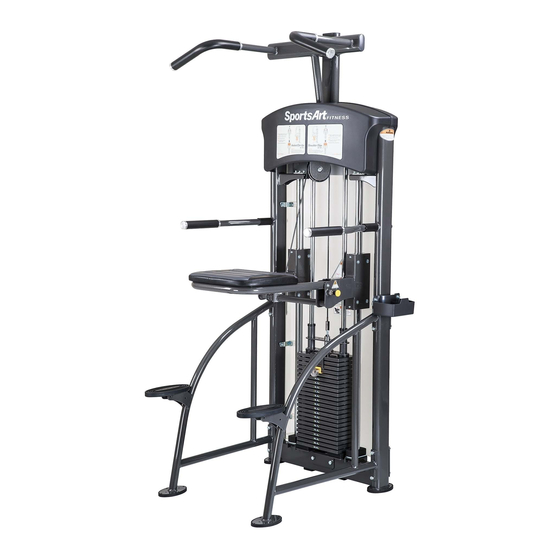
Summary of Contents for SportsArt Fitness DF-107
-
Page 1: Table Of Contents
TABLE OF CONTENTS - Chapter 1 Safety Instructions..................1.1 Safety Precautions....................- Chapter 2 Instructions....................2.1 Dimensions......................2.2 Part List For Box A....................2.3 Part List For Box C....................2.4 Components in the Hardware Kit................2.5 Components on the Product.................. -... -
Page 2: Chapter 1 - Safety Instructions
- CHAPTER 1 SAFETY PRECAUTIONS 1.1 SAFETY PRECAUTIONS ● Read and follow all cautionary messages and warnings in this manual. Obtain instructions on the proper user of this machine prior to exercising. Use appropriate body positioning and controlled movements. ● Assemble and operate this product on a solid, level surface. -
Page 3: Chapter 2 Instructions
- CHAPTER 2 INSTRUCTIONS 2.1 DIMENSIONS... -
Page 4: Part List For Box A
2.2 Part List For Box A Description Qty No. Description Rear Top Cover Weight Plate Sticker (5kg) Front Top Cover Weight Plate Sticker (10kg~60kg) Stack Cover Weight Plate Sticker (65kg~100kg) Bottle Holder Front Support Right Side Handle Main Frame Left Side Handle Rear Support Top Handle Frame 5kg Weight Plate... -
Page 5: Part List For Box C
2.3 Part List For Box C Description Qty No. Description 5 KG Weight Plate 2.4 Components in the Hardware Kit A hardware kit is provided in the packaging of this product. Please inspect the hardware kit for the following items. Description Specification Tool Needed... -
Page 6: Components On The Product
2.5 Components on the Product Some components are installed on the product. These items will be needed for product assembly. Tool Needed Specification Description Hex bolt M10*L130 Spring washer ψ ψ Flat washer 10.2 ∮ 50 connector Hex locknut Inner hex screw M6*L8 Set ring A Set ring B... -
Page 7: Chapter 3 Assembly Instructions
- CHAPTER 3 ASSEMBLY INSTRUCTIONS Before Assembly Before tilting up the main frame (5), make sure that set rings A,B (57,58) are in place. Otherwise, the knee platform (69) can slide downward. After preventing the knee platform (69) from sliding, tilt the main frame (5) upward as shown. -
Page 8: Step 1 Support Arm, Bottle Holder, And Rear Support Installation
STEP 1 Support Arm, Bottle Holder, and Rear Support Installation... - Page 9 1-1. Connect the front support (11) to the main frame (5). Attach connector (54) with hardware (51,52,53,55) but do not fully tighten bolts.
- Page 10 1-2. Hang the bottle holder (4) on screws (51) at area A as shown.
- Page 11 1-3. Use connector (71) and hardware (52,55,70,53) to secure the rear support (6) in place as shown. 1-4. Put the unit flat on the floor, then fully secure hardware (51,52,53,55,70,53). -10-...
-
Page 12: Step 2 Weight Plate And Cable Installation
Weight Plate and Cable Installation STEP 2 -11-... - Page 13 2-1. Hold the upper stack carriage set (59). Then cut the zip tie that holds it in place. Gently lower the upper stack carriage set (59) into place as shown. -12-...
- Page 14 2-2. Remove hardware (60,61,62). Then guide the guide rods (63) downward as shown. -13-...
- Page 15 2-3. Tilt the guide rods (63) backward as shown. Then lift the upper stack carriage set (59) from the guide rods as shown. Carefully set the upper stack carriage set aside. -14-...
- Page 16 2-4. Follow steps below to separate the stack fork cartridge from the upper stack carriage set. E1. Insert a tool into the hole shown in figure #1. E2. Remove screws (72,73), stack carriage set (74), and stack fork (64). -15-...
- Page 17 2-5. Insert and lower the 22 5KG weight plates (7) into place on the guide rods as shown. NOTE : The convex side faces up. 2-6. After putting weight plates (7) into place, insert and lower the upper stack carriage set (59) into place.
- Page 18 2-7. Tilt the guide rods (63) back into place. -17-...
- Page 19 2-8. Lift the guide rods (63) up into their mounting station. Then secure them with hardware (60,61,62). -18-...
- Page 20 2-9. Follow steps below in the order presented. Note: Lift the upper stack carriage (59) slightly to assist installation of the stack fork (64) and stack fork cartridge (74). F1. Insert the stack fork (64) below the fifth weight plate or lower [#4]. F2.
- Page 21 2-10. Use scissors to cut the zip tie. Unwrap the cable. Make sure it lies in the groove of pulley in area B as shown. Connect the cable to the central weight stack rod as shown. 2-11. Cable adjustment: First insert a tool into (Z) hole. Then pull the cable into place and use an open-end wrench to secure it.
-
Page 22: Step 3 Apply The Weight Stack Sticker
Apply the Weight Stack Sticker STEP 3 -21-... - Page 23 Before applying weight plate stickers, please wipe the area clean, and clean your hands before proceeding to the next step. 3-1. Align and tape the cardboard to the upper left corner of the fourth weight plate (7). 3-2. Peel off the top half of the weight sticker (9) backing. Note: leave the clear outside ’...
-
Page 24: Step 4 Install The Top Handle Frame
Top Handle Frame Installation STEP 4 4-1. Put the top handle frame (14) on the main frame (5). Secure it with hardware (52, 55,75,76), but do not firmly tighten the hardware yet. 4-2. Put on upper hardware (65,52,53,66,55) then secure it. Then fully secure other hardware (52,55,75,76). -
Page 25: Step 5 Side Handle Installation
Install the Side Handle STEP 5 5-1. Remove hardware (56,57) from the left and right side handles (12,13). 5-2. Insert right and left side handles (12,13) onto their mount stems on the main frame and secure them in place with hardware (56,57) as shown. 5-3. -
Page 26: Step 6 Installation
Installation STEP 6 6-1. Remove the guide rod clamp A,B and hardware (57,58,77) and install it on the upper part of the rods as shown. NOTE: Have another person hold the knee platform for safety while you perform this step. -25-... -
Page 27: Step 7 Weight Stack Back Cover Installation
Weight Stack Back Cover Installation STEP 7 7-1. First, identify left and right side back cover brackets A, B (31,32). Then use hardware (33) to secure back cover brackets onto stack cover (3) left and right sides as shown. 7-2. Then hook the stack cover (3) onto the screw (78). -26-... - Page 28 7-3. Hang upper back cover (3) onto screws (78). Simultaneously, hook upper rear cover (3) into cower rear cover (3). -27-...
-
Page 29: Step 8 Front Top Cover Installation
STEP 8 Front Top Cover Installation 8-1. Use screws (33) to secure the front top cover (2) onto the frame as shown. -28-... -
Page 30: Step 9 Rear Top Cover Installation
Rear Top Cover Installation STEP 9 9-1. First, press the screw sockets (34) into place in eight square holes on the frame as shown. 9-2. Use screws (33) to secure the two rear cover brackets (35) in place on the frame as shown. -
Page 31: Step 10 Stack Fork Operation
STEP 10 Stack Fork Operation 10-1. Insert the stack fork to make sure that every weight plate can be engaged easily. -30-... -
Page 32: Chapter 4 Operating Instructions
- CHAPTER 4 OPERATING INSTRUCTIONS 4.1 Operating the Product To change the knee platform position, pull out knob F. The knee platform can be placed up, out of the way, or down, in place to assist you. -31-... -
Page 33: Testing
4.2 Testing Please see operating instructions on the product. Exercise as instructed to test unit operation. Insert the stack fork at the heaviest weight setting at which you can safely operate the equipment. Exercise to lift the stack several times. Then inspect the cable for proper tightness. -
Page 34: Maintenance
4.3 Maintenance 1. Apply lubricant to the guide rods every four months. 2. Procedure: (a) Put some lubricant on a clean, lint-free cloth. Rub the lubricated cloth on the guide rods. (b) Load the upper stack carriage. Exercise to test operation. (c) Repeat steps (1) and (2) 2-3 times.
Need help?
Do you have a question about the DF-107 and is the answer not in the manual?
Questions and answers