
Subscribe to Our Youtube Channel
Related Manuals for SportsArt Fitness A989


Summary of Contents for SportsArt Fitness A989
- Page 1 A989 Hack Squat Owner’s Manual Sports Art Industrial Co., Ltd. TUV-CERT ISO 9001/9002/14000 Certifi ed Quality Products 2013.01...
- Page 2 A989 OWNER’S MANUAL CONTENTS 1. INTRODUCTION ................2 2. SAFETY PRECAUTIONS ..............3. LIST OF PARTS ................. 4. ASSEMBLE THE PRODUCT ............. STEP 1 Assemble the Main Components ..........STEP 2 Install the Cushions and Handles ..........STEP 3 Install the Weight Plate Pegs ..........11 STEP 4 Level the Unit ................
-
Page 3: Introduction
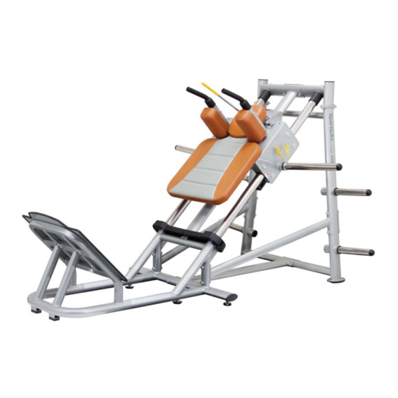
1. INTRODUCTION Congratulations on the purchase of a high quality SportsArt product, the A989 hack squat machine. Constructed of high quality materials and designed for years of reliable performance, this product was made for full commercial use. Before this product is assembled or operated, we recommend that you familiarize yourself with this manual. -
Page 4: Safety Precautions
2. SAFETY PRECAUTIONS This product was designed and built for optimum safety. However certain precau- tions apply during the use of this product. Please note the following safety precautions: • Please read the entire manual before assembly and operation. Make sure the product is installed and operated as instructed in this manual. -
Page 5: List Of Parts
3. LIST OF PARTS Assembly Parts No. Name Qty. No. Name Qty. A1 Upright frame Cover A2 Base A10 Security clip A3 Link tube A11 Cover set plate A4 Connector plate A12 Clip A5 Inclined frame A13 Lower left bracket tube A6 Weight plate peg A14 Lower right bracket tube A7 Weight plate peg (long) -
Page 6: Components In The Hardware Kit
Components on the Product Name Qty. Specification Notes Mushroom top inner hex screw M8*P1.25*L20 Spring washer Flat washer D22*d8.2*t2 Mushoom top inner hex screw M8*P1.25*L20 Spring washer Handle washer D18*d8.5*t2 Mushroom top inner hex screw M6*P1.00*L15 Handle washer D20*d7*t2.0 Inner hex screw M5*P0.8*L15 Flat washer D16*d6.3*t2... -
Page 7: Assemble The Product
4. ASSEMBLE THE PRODUCT Follow instructions below to assemble this product. Note that in this manual the words “left” and “right” are used to refer to the product and its parts. As such, these designations correspond to the “left” and “right” sides of a person in position to exercise on this product. - Page 8 STEP 1 Assemble the Main Components (Continued) (c) First remove the screws (36) from upright frame (A1). In area (A), align the holes of the inclined frame (A5) with the top of the upright frame (A1), then loosely secure both frames with the screws (36). In area (B), align the holes of the bottom of the incline frame (A5) with the base frame (A2), then tighten the screws (35).
- Page 9 STEP 1 Assemble the Main Components (d) In area B, Insert the clip (A12) under the metal plate of the inclined frame (A5), then secure the clip with 3 screws (34) from the bottom. Attach both covers (A9) onto the connecting plate under the Inclined frame (A5), secure the covers with the other 8 screws (34).
- Page 10 STEP 1 Assemble the Main Components Assemble the bracket tubes Attach the front end of the lower right bracket tube (A14) and the connector plate (A4) onto the upright frame (A1), secure tightly with screws (41). Then attach the back end of the lower right bracket tube (A14) and the the connec- tor plate (A4) onto the base frame (A2), secure tightly with screw (41).
- Page 11 STEP 2 Install Cushions and Handles Please follow instructions (a) through (d) to install shoulder cushions and handles. (a) Remove screws (31) from shoulder cushions (A11). (b) Hold shoulder cushions onto their mount plates and secure then with screws (31). (c) Remove screws (32) from handles (A8), and push covers toward the han- dles.
- Page 12 STEP 3 Install Weight Plate Pegs Please follow instructions (a) through (b) to install weight plate pegs. (a) First, remove screws from weight plate pegs (A6) and (A7). (b) Insert weight plate short pegs (A6) into area (A). Insert the weight plate long pegs (A7) into area (B) on both sides of the unit.
-
Page 13: Step 4 Level The Unit
STEP 4 Level the Unit Follow instructions (a) through (c) to level the unit. (a) Rotate the set screw to allow adjustment of the leveler foot. (b) Rotate the leveler foot downward against the floor. (c) Rotate the set screw upward against the frame to secure this position. -
Page 14: Operate The Product
5. OPERATE THE PRODUCT This section includes operational instructions. OPERATION Placement Settings Follow instructions (a) through (c) below to establish placement settings for your height. (a) Push the inclined frame upward and hold it there. (b) Press the placement setting lever downward, making the hook rise. -
Page 15: Operation Operate The Product
OPERATION Operate the Product (a) Select the appropriate weight plates placed on both sides of the weight plate pegs, and then secure the weight plates with safety clamps. (b) Open foot stance slightly wider than shoulder width, perpendicular to the foot mat. -
Page 16: Maintenance
6. MAINTENANCE This section covers maintenance topics, including glide rail cleaning, a schedule, a list of tasks, and a page for record keeping. MAINTENANCE Glide Rail Cleaning Please follow instructions below to clean glide rails every day. (a) Use a clean, lint-free cloth to wipe clean the glide rails on which the in- clined frame slide. - Page 17 MAINTENANCE Schedule Area Week Month Quarter Year Notes Exterior Clean. Screws Inspect for looseness and secure if necessary. Cushions Wipe with a damp cloth. Glide rails Wipe clean with a cloth. Rollers Apply lubricant and spin rollers.
-
Page 18: Maintenance Task List
MAINTENANCE Task List Like cars, fitness products require maintenance. Regular maintenance ex- tends product life, and failure to maintain products can void the manufac- turer’s warranty. Copy the maintenance log sheet, and record maintenance work for each fitness product. Daily tasks 1. - Page 19 MAINTENANCE One-Year Maintenance Log Facility:_______________________ Supervisor:____________________ Product model number:__________ Serial number:_________________ Start date: ____________________ End date:_____________________ Daily Tasks Weeks 1-7 Weeks 8-14 Weeks 15-21 Week 22-28 Completed Daily Tasks Week 29-35 Week 36-42 Week 43-49 Week 50-52 Completed Weekly Tasks Weeks 1-7 Weeks 8-14 Weeks 15-21 Weeks 22-28...
-
Page 20: Consignes De Sécurité Importantes
7. CONSIGNES DE SÉCURITÉ IMPORTANTES Le produit SportsArt a été conçu et fabriqué afin d’assurer une sécurité optimale. Cependant certaines précautions s’appliquent chaque fois que vous utilisez votre produit. • Lisez entièrement le manuel avant l’assemblage et l’utilisation. Veuillez aussi noter les consignes de sécurité... - Page 21 • Ce produit n’est pas destiné à être utilisé par des personnes (y compris des enfants) dont les capacités physiques, sensorielles ou mentales sont réduites ou qui ne disposent pas de l’expérience ou du savoir nécessaires, sauf si celles-ci ont au préalable été formées eu égard à l’utilisation de ce produit par une per- sonne responsable de leur sécurité.
Need help?
Do you have a question about the A989 and is the answer not in the manual?
Questions and answers