Table of Contents
Advertisement
Quick Links
P857 OWNER'S MANUAL CONTENTS
1. INTRODUCTION .................................................................................................................
2. SAFETY PRECAUTIONS ....................................................................................................
3. LIST OF PARTS ..................................................................................................................
4. ASSEMBLE THE PRODUCT ...............................................................................................
STEP 1 Cover Support Plate and the Connector Installation...................................................
STEP 2 Weight Stack Installation............................................................................................. 13
STEP 3 Cam Installation.......................................................................................................... 17
STEP 4 Cable Installation......................................................................................................... 19
STEP 5 Handle Installation....................................................................................................... 23
STEP 6 Cylindrical Cushion Arm Installation............................................................................ 24
STEP 7 Seat Bottom and Cylindrical Cushion Installation........................................................ 25
STEP 8 Apply the Weight Stack Sticker.................................................................................... 27
STEP 9 Front Cover and the Rear Cover Installation .............................................................. 28
STEP 10 Install plastic cover ................................................................................................... 31
STEP 11 Install cap nut ............................................................................................................ 32
STEP 12 Secure the Product .................................................................................................. 33
STEP 13 Level the Product..................................................................................................... 34
STEP 14 Cable Adjustment...................................................................................................... 35
STEP 15 Stack Fork Inspections............................................................................................... 36
STEP 16 Unit Inspection.......................................................................................................... 37
5. OPERATION INSTRUCTION .............................................................................................. 38
OPERATION Safety Operating Area ....................................................................................... 38
OPERATION Exercising Instructions ...................................................................................... 39
6. MAINTENANCE ................................................................................................................... 43
MAINTENANCE Safety Precautions ...................................................................................... 43
MAINTENANCE Guide Rod Cleaning and Lubricating ............................................................ 44
MAINTENANCE Schedule ....................................................................................................... 45
MAINTENANCE Task List ....................................................................................................... 46
MAINTENANCE One-Year Maintenance Log .......................................................................... 47
7. CONSIGNES DE SÉCURITÉ IMPORTANTES ................................................................... 48
8. APPENDIXES ...................................................................................................................... 49
APPENDIXES Optional accessories ........................................................................................ 49
Disclaimer
The information in this user manual is subject to change without prior notice.
Sports Art Industrial Co., Ltd. makes no representation or warranty of any kind, express or
implied, regarding the marketability of this manual, the suitability for a special purpose, or any
other matters.
SportsArt Industrial Co., Ltd. accepts no responsibility for any errors in this manual, or any
damages incurred directly, indirectly, accidently, or continually from the modification, display, or
other use of this manual.
*We reserve the right to revise this manual at any time without notice.
1
2
3
4
9
9
Advertisement
Table of Contents

Subscribe to Our Youtube Channel
Related Manuals for SportsArt Fitness P857


Summary of Contents for SportsArt Fitness P857
-
Page 1: Table Of Contents
P857 OWNER’S MANUAL CONTENTS 1. INTRODUCTION ......................... 2. SAFETY PRECAUTIONS ....................3. LIST OF PARTS ........................4. ASSEMBLE THE PRODUCT ....................STEP 1 Cover Support Plate and the Connector Installation........... STEP 2 Weight Stack Installation..................... 13 STEP 3 Cam Installation......................17 STEP 4 Cable Installation...................... -
Page 2: Introduction
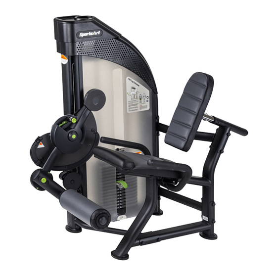
1. INTRODUCTION Congratulations on the purchase of a high quality SportsArt product, the P857 machine. Constructed of high quality materials and designed for years of reliable performance, this product was made for full commercial use. Before this product is assembled or operated, we recommend that you familiarize yourself with this manual. -
Page 3: Safety Precautions
2. SAFETY PRECAUTIONS This product was designed and built for optimum safety. However certain precautions apply during the use of this product. Please note the following safety precautions: • Please read the entire manual before assembly and operation. Make sure the product is installed and operated as instructed in this manual. -
Page 4: List Of Parts
3. LIST OF PARTS Box A A9-2 A9-1... - Page 5 Box B Box C +Box D...
- Page 6 Box A - Main Frame Components Name Qty. Name Qty. Left/right perforated boards Cover support plate A Left/right side cover Pulley cover Main frame Pulley Cover support plate B-2 Rear cover Cover support plate B-1 Front cover Front cover A Bracket Stack fork Bracket...
- Page 7 Components in the Hardware Kit Name Qty. Specification Notes Screw soft cap Phillips screw M6*P1.0*L12 Screw socket 1 batch SGN- 07 Mushroom top inner hex screw M6*P1.0*L12 Mushroom top Phillips screw M5*L15 Mushroom top Phillips screw M5* 0. 8* L8 Round sticker Phillips pan head sheet metal M4*L12...
- Page 8 Components on the Product Name Specification Notes Mushroom top inner hex screw M6*P1.0*L20 Mushroom top inner hex screw M6*P1.0*L12 Spring washer Flat washer D20*d6.3*t1.5 CAM stop plate Mushroom top inner hex screw M6*P1.0*L10 Cable set block Mushroom top inner hex screw M6*P1.0*L20 Spring washer Nylon hex lock nut...
-
Page 9: Assemble The Product
4. ASSEMBLE THE PRODUCT Follow instructions below to assemble this product. Note that in this manual the words “left” and “right” are used to refer to the product and its parts. As such, these designations correspond to the “left” and “right” sides of a person in position to exercise on this product. Also, for brevity, the word “screws”... - Page 10 STEP 1 Cover Support Plate and Connector Installation (CONT.) (a). Insert the screw sockets (14) into place in the main frame (A3) as shown, and then use the screws (15) (16) to secure the brackets (A16) (A17) in place. (Note: The bracket (A16) must be secured to the top of maim frame as shown.)
- Page 11 STEP 1 Cover Support Plate and Connector Installation (CONT.) (b). Use the screws (17) to secure the cover support plates (A10) to the straight frame of the main frame (A3) and then secure the cover support plates (A4) (A5) to the both side of the curved frame as shown.
- Page 12 STEP 1 Cover Support Plate and Connector Installation (CONT.) (c). Use the screws (21) to secure the connecting board A (A31) to the connector C (A29) and the main frame (A3) in area A. Use the screws (21) to secure the connecting board (A30) to the connector C (A29) and the seat frame (A24) in area B.
- Page 13 STEP 2 Weight Stack Installation...
-
Page 14: Step 2 Weight Stack Installation
STEP 2 Weight Stack Installation (CONT.) (a) Hold the upper stack carriage set (22), and then cut the zip tie. Gently lower the upper stack carriage set (22) into place as shown. (b) Remove the screws (23). Set the guide rod (24) downward into place as shown. (c) Tilt the guide rod (24) backward and then lift the upper stack carriage set (22) off the guide rods as shown. - Page 15 STEP 2 Weight Stack Installation (CONT.) (d) Loosen and remove the screws (25) from the stack fork (A7) and insert the weight stack rod (A8) into the central mounting position of the upper stack carriage set (22). Use the screws (25) to secure the stack fork (A7) into place of the upper stack carriage set (22) as shown.
- Page 16 STEP 2 Weight Stack Installation (CONT.) (f) Tilt the guide rods (24) back into place and then lift them up to their mounting position, and then secure the assembly with screws (23). *Install the cap nuts on the screws.
- Page 17 STEP 3 CAM Installation...
-
Page 18: Step 3 Cam Installation
STEP 3 CAM Installation (CONT.) (a) Loosen and remove screw (26) and the cap (27) from the CAM (A20). (b) Place the CAM (A20) horizontally into its mounting area, and then rotate the cam so that the rotator arm is pointing downward as shown. (Note: Due to the CAM hasn’t been connected to the cable yet, to avoid any injuries, please make sure no one is near the CAM.) (c) Secure the axle cover (27) in place with screws (26), and then apply the round sticker (18) as... - Page 19 STEP 4 Cable Installation...
- Page 20 STEP 4 Cable Installation (CONT.) (a) Insert the cable nut as indicated by the arrows onto the weight stack rod (A8) at least 15- 20mm deep as shown. (b) Take out the stack fork (A7) and lift the upper stack carriage set (20) up. (c) Insert the stack fork (A7) into the stack rod (A8) so that the cable is loose.
-
Page 21: Step 4 Cable Installation
STEP 4 Cable Installation (CONT.) (a) Loosen and remove screws (29) (31) (33), the cable set block (32) and the CAM support plate (30) from the main frame. (b) Install the pulley (A13) and insert the cable goes through the pulley (A13) as indicated by the arrows, and then secure the pulley cover (A12) in place with screws (29). - Page 22 STEP 4 Cable Installation (CONT.) (d) After completing the cable installation, hold the upper stack carriage set (22), and then take out the stack fork (A7). Gently lower the upper stack carriage set (22). (Note: Please make sure that the cable is running in the grove of the pulley. Rotate the CAM to check for cable interference and its tightness.
-
Page 23: Step 5 Handle Installation
STEP 5 Handle Installation (a). Loosen and remove the screws (35) from the handle (A21). (b). Rest the handle (A21) beneath the seat frame (A24) as shown, and then secure the screws (35). -
Page 24: Step 6 Cylindrical Cushion Arm Installation
STEP 6 Cylindrical Cushion Arm Installation (a). First, remove the screws (34) from the cylindrical cushion arm (A26). (b). Insert the cylindrical cushion arm (A26) onto the CAM (A20). Secure it in place with the screw (34) and the screw soft cap (12). -
Page 25: Step 7 Seat Bottom And Cylindrical Cushion Installation
STEP 7 Seat Bottom and Seat Back Installation... - Page 26 STEP 7 Seat Bottom and Seat Back Installation (CONT.) (a) First, remove the screws (38) (40) from the seat bottom (A25), the seat back (A23) and the seat back mount. (b) Use the screws (38) to secure the seat bottom (A25) to the seat frame (A24). (c) Use the screws (40) to secure the seat back plate (39) to the seat back mount and secure the seat back (A23) to the seat back plate (39) with the screws (38).
-
Page 27: Step 8 Apply The Weight Stack Sticker
STEP 8 Apply the Weight Stack Sticker Note: Before applying weight plate stickers, please wipe the area clean, and clean your hands before proceeding to the next step. (a) Align and tape the cardboard to the upper left corner of the weight plate (A40). (b) Peel off the top half of theweight plate sticker (A41) backing. -
Page 28: Step 9 Front Cover And The Rear Cover Installation
STEP 9 Front Cover and Rear Cover Installation (a) Loosen and remove the screws (41) from the main frame. (b) Install the square snap bushings (14) to the anchor brackets of shroud (square hole) (A9-1). Secure the anchor brackets of shroud (square hole) (A9-1) with the square snap bushings (14) to the front and back of the upper crossmember assembly of weight stack tower (A3) with screws (41). - Page 29 STEP 9 Front Cover and Rear Cover Installation (CONT.) (c) Take out the stack fork (A7) and place it on the upper stack carriage set (22) as shown to avoid damaging to the cover. (d) Slide the front cover (A15) from the top down into the cover support plates’ grooves (A5) (A10).
- Page 30 STEP 9 Front Cover and Rear Cover Installation (CONT.) (g) Slide the rear cover (A14) from top down into the cover support plates’ grooves (A4) (A10). (h) Secure the lower shroud with the screw (46).
-
Page 31: Step 10 Install Plastic Cover
STEP 10 Install plastic cover (a) Install the square snap bushing (14) and fastener (59) to the anchor bracket (A34) and remove the screws (47) on the main frame. Secure the anchor bracket (A34) to the main frame with the screws (47). (b) Secure the left/right perforated boards (A1) to the main frame with the screws (21). -
Page 32: Step 11 Install Cap Nut
STEP 11 Install cap nut Install the cap nuts to the corresponding positions according to the following numbers. GBA-P019 GBA-P024 GBA-P014 GFA-P136 GBA-P018 GBA-P017 GBA-P016 TAO-P096A GFA-P137 GFA-P138... -
Page 33: Step 12 Secure The Product
STEP 12 Secure the Product (a) Remove screws (43) from the ground fixing bracket (A18). (b) Insert the U clip (A19) onto the machine (Make sure the U clip with the correct side downward as below shown), and then secure the ground fixing bracket (A18) with screws (43). (c) Secure the ground fixing bracket on the ground with the ground fixing bolt, nut and washer as shown to make sure the machine is stable on the ground. -
Page 34: Step 13 Level The Product
STEP 13 Level the Product If the product is installed on an uneven surface to cause the instability of the product, place the support spacer under the foot pad to make sure its stability. (A few support spacers are provided in the packaging of this product.) -
Page 35: Step 14 Cable Adjustment
STEP 14 Cable Adjustment * Insert the stack fork into the gap under the lowest weight plate, and then adjust the large nut at area C. Adjust until the upper stack carriage set moves slightly. To adjust the cable, first insert the (Z) rod and loosen the (Y) nut, and then adjust the (X) nut. -
Page 36: Step 15 Stack Fork Inspections
STEP 15 Stack Fork Inspections * Please follow operating instructions on the product sticker to test operation and confirm that the equipment is working properly. * Insert the stack fork to make sure that every weight plate can be engaged easily. * Insert the stack fork at the heaviest weight setting at which you can safely operate the equip- ment. -
Page 37: Step 16 Unit Inspection
STEP 16 Unit Inspection After completing the assembly or regular maintenance, please follow instructions (a) through (c) below to inspect the unit. If the unit is disassembled or has been damaged in any way, it might cause injuries or cause the unit to fail. (a) Make sure the unit is steady and on a level surface. -
Page 38: Operation Instruction
5. OPERATION THE PRODUCT OPERATION Safety Operating Area (a) Make sure operate the unit in safety area as shown. Do not allow people to be near this area when operating. (b) Noise emission under load is higher than without load. (c) Over exercising or improper workout position may result in serious injury. -
Page 39: Operation Exercising Instructions
OPERATION Exercising Instructions (a) Select the appropriate weight plates according to your recommended exercise level. (b) Adjust the cylindrical cushion to the most comfortable position and make sure the knob is en- gaged to secure the position. (c) Perform the exercise in a controlled manner. Inhale when pushing up against resistance and exhale when returning to original position. - Page 40 OPERATION Exercising Instructions (CONT.) * Pull out the knob to adjust the cylindrical cushion arm position. You can rotate and secure the cylindrical cushion arm as desired for use within a 360 degree range. When released, the knob automatically engages to secure the position.
- Page 41 OPERATION Exercising Instructions (CONT.) *Pull out the knob on the rotator arm of CAM. Place the rotator as desired for use. When re- leased, the knob automatically engages to secure the position.
- Page 42 OPERATION Exercising Instructions (CONT.) * To move the seat back position toward yourself, simply pull it. To move the seat back away from yourself, pull the knob and press the seat back.
-
Page 43: Maintenance
6. MAINTENANCE This section covers maintenance topics and includes a maintenance schedule, task list, and log. MAINTENANCE Safety Precautions ● Please follow standard safety precautions when servicing this product. ● Do NOT use a water damp towel to clean the product and do perform the following mainte- nances. -
Page 44: Maintenance Guide Rod Cleaning And Lubricating
MAINTENANCE Guide Rod Cleaning and Lubricating 1. Apply lubricant to the guide rods every week. Procedure: (a) Put some lubricant on a clean, lint-free cloth. Rub the lubricated cloth on the guide rods. (b) Load the upper stack carriage set. Exercise to test operation. (c) Repeat steps (a) and (b) 2-3 times. -
Page 45: Maintenance Schedule
MAINTENANCE Schedule If there is a need for maintenance of components, please visit the SportsArt website. cleaning requirements 1.directive 93/42/CEE 2.directive biocide 98/8/CEE The disinfectant has to be in compliance with Medical Device Directive 93/42/EEC (MDD) and Biocidal Products Directive 98/8/EC (BPD). It is suited for sensitive synthetic surfaces such as synthetic leather, polycarbonate (PC), acrylic glass and polysulfone, and for the keyboards and control panels. -
Page 46: Maintenance Task List
MAINTENANCE Task List Like cars, fitness products require maintenance. Regular maintenance extends product life, and failure to maintain products can void the manufacturer’s warranty. Copy the maintenance log sheet, and record maintenance work for each fitness product. Daily tasks 1. Use a clean, lint-free towel to wipe down the product exterior. 2. -
Page 47: Maintenance One-Year Maintenance Log
MAINTENANCE One-Year Maintenance Log Facility:_______________________________ Supervisor:_____________________________ Product model number:__________________ Serial number:__________________________ Start date: ____________________________ End date:______________________________ Daily Tasks Weeks 1-7 Weeks 8-14 Weeks 15-21 Week 22-28 Completed Daily Tasks Week 29-35 Week 36-42 Week 43-49 Week 50-52 Completed Weekly Tasks Weeks 1-7 Weeks 8-14 Weeks 15-21... -
Page 48: Consignes De Sécurité Importantes
7. CONSIGNES DE SÉCURITÉ IMPORTANTES Le produit SportsArt a été conçu et fabriqué afin d’assurer une sécurité optimale. Cependant certaines précautions s’appliquent chaque fois que vous utilisez votre produit. • Lisez entièrement le manuel avant l’assemblage et l’utilisation. Veuillez aussi noter les consignes de sécurité... -
Page 49: Appendixes
8. APPENDIXES APPENDIXES Optional accessories Top weight(100 kg = (5KG × 1 pcs) + (5KG × 7 pcs) + (7.5KG × 8 pcs) - Page 50 8. APPENDIXES APPENDIXES...
- Page 51 Your Authorized Distributor...
Need help?
Do you have a question about the P857 and is the answer not in the manual?
Questions and answers