Table of Contents
Advertisement
Quick Links
E845S OWNER'S MANUAL CONTENTS
1. INTRODUCTION ..............................................................................
2. SAFETY PRECAUTIONS ................................................................
3. LIST OF PARTS ...............................................................................
4. ASSEMBLE THE PRODUCT ..........................................................
STEP 1 Install the Frame ....................................................................
STEP 2 Install the Glide Rail ...............................................................
STEP 3 Install the Pedestal Covers ....................................................
STEP 4 Install the Foot Pedals ..........................................................
STEP 5 Move the Product into Place ..................................................
STEP 6 Level the Product ...................................................................
STEP 7 Ground Wire Installation .........................................................
STEP 8 Beware of Moving Parts .........................................................
5. UNDERSTAND THE E845S DISPLAY ............................................
DISPLAY Overview ..............................................................................
DISPLAY Specifications .......................................................................
DISPLAY Windows ............................................................................... 23
DISPLAY Keys ...................................................................................... 23
6. OPERATE THE PRODUCT .............................................................
OPERATION Quick Start .....................................................................
OPERATION Start a Workout Program ...............................................
OPERATION Display ...........................................................................
OPERATION Cool Down .....................................................................
OPERATION Review Summary ..........................................................
OPERATION Workout Programs .........................................................
OPERATION User Preferences and Component Versions...................
7. ABOUT HEART RATE DETECTION ................................................
HEART RATE Telemetry ......................................................................
HEART RATE Contact .........................................................................
8. GUIDELINES FOR EXERCISE .......................................................
9. ACCESSORIES ...............................................................................
ACCESSORIES Entertainment Cap ...................................................... 34
ACCESSORIES MYE Wireless TV Audio_Channel Receivers ............. 35
10. MAINTENANCE .............................................................................
MAINTENANCE Lubrication Procedure ............................................... 37
MAINTENANCE Cleaning the Glide Rails ............................................ 39
MAINTENANCE Messages .................................................................. 40
MAINTENANCE Schedule ...................................................................
MAINTENANCE Task List (Elliptical Trainers) .....................................
MAINTENANCE One-Year Maintenance Log ......................................
MAINTENANCE Electronics Block Diagram ........................................
2
3
7
9
9
14
15
16
18
19
20
21
22
22
23
25
25
25
26
26
26
27
29
31
31
31
32
33
37
41
42
43
44
Advertisement
Table of Contents

Subscribe to Our Youtube Channel
Related Manuals for SportsArt Fitness E845S


Summary of Contents for SportsArt Fitness E845S
-
Page 1: Table Of Contents
STEP 5 Move the Product into Place ..........STEP 6 Level the Product ..............STEP 7 Ground Wire Installation ............STEP 8 Beware of Moving Parts ............5. UNDERSTAND THE E845S DISPLAY ..........DISPLAY Overview ................DISPLAY Specifications ............... DISPLAY Windows ................23 DISPLAY Keys .................. -
Page 2: Introduction
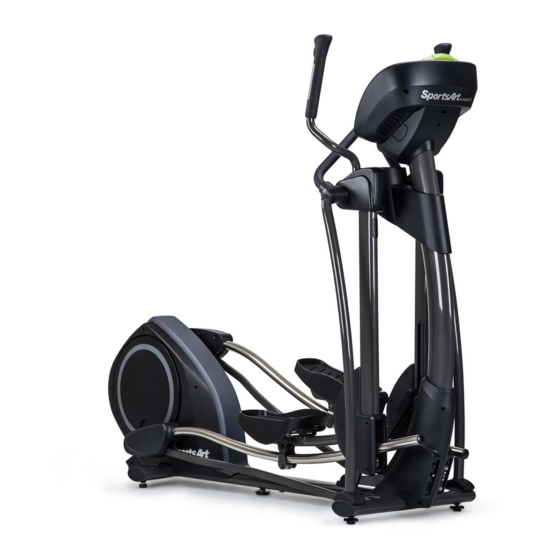
1. INTRODUCTION Congratulations on your purchase of one of the finest exercise products on the market today, the SportsArt E845S Elliptical trainer. Constructed of high quality materials and designed for years of reliable usage, this product was made to become an integral part of your commercial fitness venue. -
Page 3: Safety Precautions
2. SAfETy PRECAUTIONS Your SportsArt elliptical trainer was designed and built for optimum safety. However certain precautions apply whenever you use your elliptical trainer. Please read the entire manual before assembly and operation. Also, please note the following safety precautions: ●... - Page 4 2. SAfETy PRECAUTIONS (CONTINUED) Caution If you feel any pain or abnormal sensation, STOP YOUR WORKOUT and consult your physician immediately. Work within your recommended exer- cise level. DO NOT work to exhaustion. Before beginning any exercise program, you should consult with your doc- tor.
- Page 5 2. CONSIGNES DE SÉCURITÉ IMPORTANTES • Votre elliptique SportsArt a été conçu et fabriqué afin d’assurer une sé- curité optimale. Cependant certaines précautions s’appliquent chaque fois que vous utilisez votre tapis de course. • Lisez entièrement le manuel avant l’assemblage et l’utilisation. Veuillez aussi noter les consignes de sécurité...
- Page 6 2. CONSIGNES DE SÉCURITÉ (SUITE) ATTENTION Si vous ressentez une douleur ou si vous avez une sensation anormale, ARRÊTEZ VOTRE ENTRAÎNEMENT et consultez immédiatement votre médecin. Entraînez-vous à votre niveau d’exercice recommandé. NE PAS s’entraîner jusqu’à l’épuisement. Avant de commencer un programme d’exercice, vous devriez consulter votre médecin.
-
Page 7: List Of Parts
3. LIST Of PARTS Assembly Parts Qty. No. Qty. Name Name Main frame Left roller cover Stationary handlebar Support tube, left Pedestal covers, left Support tube, right and right Stationary handlebar A10 Foot pedals cover, left Stationary handlebar A11 Hardware kit cover, right Right roller cover A12 Glide rail cover... - Page 8 3. LIST Of PARTS (CONTINUED) Components in the Hardware Kit Name Qty. Specification Notes Mushroom top inner hex screw M10*P1.5*L25 Serrated washer D20*d10.2*t2.0 Secondary guide roller bolt D9.96*L54 Self-lubricating bushing Secondary guide roller D23*L45 12 Stride adjustment linkage cover Hex nut M10*P1.5 Stopper Ø30-30...
-
Page 9: Assemble The Product
4. ASSEMBLE THE PRODUCT Follow instructions below to assemble this product. Note that in this manual the words “left” and “right” are used to refer to the product and its parts. As such, these designations correspond to the “left” and “right” sides of a person in position to exercise on this product. - Page 10 STEP 1 Install the frame (Continued) (e) A: Once slip the glide rail into (Part A), then place the pedal carriage lightly on the glide rail support (Part B). Connect the secondary guide roller (11) on the bottom of the glide rail. (Please note the direction to insert the screw is from outside to inside) B: Unsecure the bolts (32) (33) from the left/right roller covers (A6) (A7) and then put the the left/right roller covers (A6) (A7) place and secure...
- Page 11 STEP 1 Install the frame (Continued) (f) Put the stride linkage in place and use the bolt (34) and washer to secure it onto the stride support assembly and then press the stride adjustment linkage covers (12) into place as shown below. Complete steps (d), (e), and (f) on the other side of the unit too.
- Page 12 STEP 1 Install the frame (Continued) (g) Secure stopper (13) on the front, bottom of both glide rails and then remove the unit from the lower box.
- Page 13 STEP 1 Install the frame (Continued) (h) (1) Loosely secure bolts (35) (36) A and B on both support tube (A8) (A9). At this point, donot tighten these bolts. (2) With hardware (37) shown in illustration I, secure the stationary handlebar (A2) at both sides and then tighten bolts (35) (36) at area A and B.
-
Page 14: Step 2 Install The Glide Rail
STEP 2 Install the Glide Rail Follow instructions (a) through (c) to install the glide rail. (a) Move part (A) of the glide rail to the upper left part of the flywheel within the 90-degree indication. Hook the part B onto the glide rail. (b) Turn part B clockwise as shown to a nearly horizontal position of the glide rail covers (A12). -
Page 15: Step 3 Install The Pedestal Covers
STEP 3 Install the Pedestal Covers Hold the pedestal covers in place. Use the screw driver provided to tighten the screws (15) into the pedestal covers (A3). -
Page 16: Step 4 Install The Foot Pedals
STEP 4 Install the foot Pedals Follow steps (a) through (b) to secure the support tubes. (a) There are rubber pads (A) on the foot pedals (A10). Fold the rubber pad (A) up to access screws. Secure the foot pedals (A10) onto the plate of main frame (A1) with screws (38) as shown. - Page 17 STEP 4 Install the foot Pedals (Details) Follow instructions (a) through (c) to install the details of the foot pedals. (a) Make sure the middle nibs on the foot pedals (A10) in area L are firmly placed into the middle holes on the foot pedals (A10). Pull the nibs through the foot pedals (A10) until they fit snugly in place.
-
Page 18: Step 5 Move The Product Into Place
STEP 5 Move the Product into Place There are two techniques for moving this product. (a) One person: Grip the front base of the product and lift upward, then push the product into location for use. Be careful to avoid pinching fingers when setting the product down. -
Page 19: Step 6 Level The Product
STEP 6 Level the Product For the user’s safety and the proper functioning of the product, this elliptical trainer must sit level on a flat floor. If necessary, adjust the levelers by following instructions (a) through (c) below. (a) Loosen the leveler nut. (b) Rotate the leveler foot downward so it firmly touches the floor. -
Page 20: Step 7 Ground Wire Installation
STEP 7 Ground Wire Installation Note: A ground wire and the following instructions are required by European safety standards. The ground wire is not required by North American safety standards. To avoid electric shock and current leakage, this product has an exterior ground wire. -
Page 21: Step 8 Beware Of Moving Parts
STEP 8 Beware of Moving Parts This product has moving parts that could be a danger to people and animals. During use, do not insert hands or other objects into the stride adjustment slot, the opening in the rear cover, or other areas in which such action might present a hazard. -
Page 22: Understand The E845S Display
5. UNDERSTAND THE E845S DISPLAy DISPLAy Overview The E845S elliptical trainer is designed for user convenience. With better feedback about your workout, you get better results. The following explains the display key and window functions. Please read this manual, understand the display functions, and thereby get optimum enjoyment and benefit from this product. -
Page 23: Display Specifications
DISPLAy Specifications ● Workout level (resistance level): 1 - 40 ● Time: 0:00 - 300:00 ● Distance: 0.00 - 9999 km or mile ● Calories: 0.0 - 9999 kcal ● Heart Rate range: 40 -250bpm ● Stride per minute (SPM): 5 – 120 (Range shown) ●... - Page 24 DISPLAy Keys (Continued) VARI-STRIDE – This workout program automatically changes stride. Exercisers can select maximum stride. fIT TEST – Press this key to enter a FIT TEST program and start the fitness test. CUSTOM HR – This heart rate control program allows you to set your own target heart rate.
-
Page 25: Operate The Product
6. OPERATE THE PRODUCT There are two ways to start operating this product, either through the QUICK START mode or through a workout program/goal. OPERATION Quick Start Time, distance and calories will count up. If a workout time limit is activated, time will count down, but distance and calories will count up continuously. -
Page 26: Operation Display
OPERATION Start a Workout Program (Continued) press QUICK START key to start this program right away with default age and weight. 3. The age setting range is from 10 to 90, with a default value of 35 years old. Use ▲/▼... -
Page 27: Operation Workout Programs
OPERATION Workout Programs The following explains features of the workout programs. MANUAL This program allows you to manually control resistance. In manual mode, simply press WORKOUT LEVEL ▲/▼ keys to control resistance, or STRIDE ▲/▼ keys to control stride length. INTERVAL There are three interval programs: INTERVAL1:1, INTERVAL1:2, INTERVAL 2:2. - Page 28 OPERATION Workout Programs (Continued) During program setting, you may press QUICK START to start the program right away. The maximum stride length can be adjusted during exercising by pressing STRIDE ▲/▼ keys. fIT TEST The FIT TEST program is designed for physical fitness assessments. The program is set with a time limit;...
-
Page 29: Operation User Preferences And Component Versions
OPERATION Workout Programs (Continued) CARDIO/WEIGHT LOSS/CUSTOM HR In these heart rate control programs, the resistance level will automatically change to keep the exerciser’s pulse at the optimum rate for achieving his or her fitness goals. Target heart rates are calculated based on a standard “maximum” heart rate for the exerciser’s age. - Page 30 OPERATION User Preferences & Component Versions (Cont.) PROGRAM TIME LIMIT The display will show “ TIME LIMIT - YES” or “TIME LIMIT - NO”, press ▲/▼ key to turn this function On/Off. Press ENTER to make your selection. When “YES” is selected, it will prompt the message of “TIME - XX:00”...
-
Page 31: About Heart Rate Detection
7. ABOUT HEART RATE DETECTION Heart rate detection functions are selected at the time of purchase. Not every product has every type of heart rate detection. The following explains factors that influence the performance of two of the most common types of heart rate detection devices. -
Page 32: Guidelines For Exercise
Note that in dry areas in particular, static electricity can interfere with unit operation and shock people. To discharge static electricity from your body, touch something else before touching metal on the product. 8. GUIDELINES fOR EXERCISE HOW HARD SHOULD I EXERCISE? Studies show that to benefit from aerobic exercise, people need to maintain a certain heart rate during their workouts. -
Page 33: Accessories
9. ACCESSORIES There are accessories attached to this console; some are standard and some are optional. The following explains the details of each accessory and its function. USB CHARGER (Standard) The USB charger will provide 5V 500mA voltage for the smart phone or other devices charging. -
Page 34: Accessories Entertainment Cap
9. ACCESSORIES (CONTINUED) Entertainment Cap (a) RFID member card slot: work with both optional SA WELL+ and ECOFIT member cards. (Not available yet.) (b) Bluetooth/WIFI connection button: press this button to pair the smart phone SA WELL+ App. (c) USB port: this port is used for device charging as well as optional data transferring. -
Page 35: Accessories Mye Wireless Tv Audio_Channel Receivers
9. ACCESSORIES (CONTINUED) MyE Wireless TV Audio_Channel Receivers: If your equipment has been installed MYE Wireless TV Audio_Channel Receivers, the display must has Channel Keys. Please make sure your equipment is with the correct sticker as below. (a) None Treadmill (Bike, Elliptical and Stepper...etc.) Left display: Without Channel Keys. - Page 36 9. ACCESSORIES (CONTINUED) MyE Wireless TV Audio_Channel Receivers fuctions: 1. The receiver has two kinds of module as below. (Note: MyE Wireless TV Audio_Channel Receivers and Module not provided.) (1). MC3R-9(900MHZ) must work with MYE Wireless TV Audio_Channel Receivers MWTD-S9. (2).
-
Page 37: Maintenance
10. MAINTENANCE Maintenance topics are presented below in the following order: error messages, lubrication of the shoulder area, lubrication of the stride area, glide rail cleaning, maintenance schedule, task list, one-year maintenance log, and electronics block diagram. MAINTENANCE Lubrication Procedure Please follow instructions (a) through (d) to lubricate the product. - Page 38 MAINTENANCE Lubrication Procedure (Continued) Please follow instructions (a) through (e) to lubricate the stride motor (a) Push in at point A, and slide upward to remove the lubrication hole cover as (1) (2) shown. (Note that point A provides the best contact surface on the lubrication hole cover.) (b) During Banner mode, the message shows “SELECT A PROGRAM”, press STRIDE ▲...
-
Page 39: Maintenance Cleaning The Glide Rails
MAINTENANCE Cleaning the Glide Rails Clean the both left and right glide rails daily as follows: (a) Use a clean, lint-free cloth to wipe dust and debris off the glide rails. (b) Operate the product to inspect it and to determine where dirt might remain on the glide rails. -
Page 40: Maintenance Messages
MAINTENANCE Messages The following messages can appear on this product for diagnostic purposes. NO STRIDE ADJUST UNDER 30SPM - Indication: stride length can not be adjusted due to speed is under 30SPM. It appears when STRIDE ▲/▼ key is pressed to adjust the stride but the actual speed is under 30SPM. SERVICE BATTERy - Indication: the battery is low. -
Page 41: Maintenance Schedule
MAINTENANCE Schedule Area Week Month Quarter year Notes Exterior Clean Inspect and Screws secure loose parts Glide Wipe away dirt rail and debris. Apply silicone Rollers lubricant. Stride Apply bearing motor grease. Lubricate with Cushion original 66A lubricant. -
Page 42: Maintenance Task List (Elliptical Trainers)
MAINTENANCE Task List (Elliptical Trainers) Like cars, fitness products require maintenance. Regular maintenance extends product life, and failure to maintain products can void the manufacturer’s warranty. Copy the maintenance log sheet, and record maintenance work for each fitness product. Daily tasks 1. -
Page 43: Maintenance One-Year Maintenance Log
MAINTENANCE One-year Maintenance Log Facility:_______________________ Supervisor:____________________ Product model number:__________ Serial number:_________________ Start date: ____________________ End date:_____________________ Daily Tasks Weeks 1-7 Weeks 8-14 Weeks 15-21 Week 22-28 Completed Daily Tasks Week 29-35 Week 36-42 Week 43-49 Week 50-52 Completed Weekly Tasks Weeks 1-7 Weeks 8-14 Weeks 15-21 Weeks 22-28... -
Page 44: Maintenance Electronics Block Diagram
MAINTENANCE Electronics Block Diagram RFID Board USB Board Control Board Continua Adapter Board Option SA WELL+ Connection key CSAFE Board HRC Board iPod Audio Board Head Phone Board Option Workout Level Switch Stride length Switch HTR Board Stepper motor Contact HTR plates Model no.
Need help?
Do you have a question about the E845S and is the answer not in the manual?
Questions and answers