Table of Contents
Advertisement
Quick Links
c575u-16 OWNER'S MANuAL cONTENTS
SENZA SERIES DISCLAIMER TERMS ...............................................
1. INTRODUCTION ...............................................................................
2. SAFETY PRECAUTIONS .................................................................
3. LIST OF PARTS ................................................................................
4. ASSEMBLE THE PRODUCT ............................................................ 11
STEP 1 Separate the Product from the Package .................................
STEP 2 Install the Rear Support ..........................................................
STEP 3 Install the Storage Tray............................................................
STEP 4 Install the Pedestal ................................................................. 14
STEP 5 Install the Seat Bottom and Pedals ......................................... 15
STEP 6 Move the Product ................................................................... 16
STEP 7 Level the Bike ........................................................................
STEP 8 Install the Power Cord ............................................................
STEP 9 TV Terminal and Network ........................................................ 19
STEP 10 Install the TV Cable ............................................................... 20
STEP 11 Seat Fore and Aft Adjustment ................................................ 21
STEP 12 Seat Height Adjustment ......................................................... 22
5. UNDERSTAND THE C575U 16" SENZA CONSOLE ....................... 23
DISPLAY Overview ............................................................................... 23
DISPLAY Keys ...................................................................................... 23
DISPLAY Windows ................................................................................ 23
6. OPERATE THE PRODUCT ............................................................... 24
OPERATION Safety Operating Area ..................................................... 24
OPERATION Proper Workout Position and Safety Get Off ................... 25
OPERATION Overview .......................................................................... 26
OPERATION Start Screen .................................................................... 26
OPERATION Start Your (GO) Workout .................................................. 27
OPERATION Workout Selection ............................................................ 27
OPERATION Workout Programs ........................................................... 28
OPERATION Workout Status ................................................................ 29
OPERATION Select Entertainment ....................................................... 30
OPERATION View Entertainment ......................................................... 31
OPERATION Workout Summary ........................................................... 32
OPERATION Idle Mode ........................................................................ 32
OPERATION Energy Smart Function ................................................... 32
OPERATION Precautions ...................................................................... 32
7. ABOUT HEART RATE DETECTION .................................................. 33
HEART RATE Telemetry ........................................................................ 33
HEART RATE Contact ........................................................................... 33
8. GUIDELINES FOR EXERCISE ......................................................... 34
9. MAINTENANCE ................................................................................ 35
MAINTENANCE Safety Precautions ..................................................... 35
MAINTENANCE Error Messages .......................................................... 35
MAINTENANCE How to Replace a Fuse .............................................. 36
MAINTENANCE Schedule .................................................................... 37
2
3
4
9
11
12
13
17
18
Advertisement
Table of Contents

Subscribe to Our Youtube Channel
Related Manuals for SportsArt Fitness C575U-16


Summary of Contents for SportsArt Fitness C575U-16
-
Page 1: Table Of Contents
OWNER’S MANuAL cONTENTS SENZA SERIES DISCLAIMER TERMS ..........1. INTRODUCTION ................2. SAFETY PRECAUTIONS ..............3. LIST OF PARTS ................4. ASSEMBLE THE PRODUCT ............11 STEP 1 Separate the Product from the Package ......... STEP 2 Install the Rear Support ............ - Page 2 OWNER’S MANuAL cONTENTS MAINTENANCE Task List ..............38 MAINTENANCE One-Year Maintenance Log ........39 10. ACCESSORIES ................40 ACCESSORIES Entertainment Cap ............. 40 11. APPENDIXES ................. 42 APPENDIXES Specifications ............... APPENDIXES Electronics Block Diagram ...........
-
Page 3: Senza Series Disclaimer Terms
SENZA SERiES diScLAiMER TERMS Internet function: A1. This machine provides only a web page browsing method for web page and video browsing. A2. For web page videos, we support only Youku and YouTube. Note: Some videos may not be viewed due to restrictions resulting from country policies, internal server firewalls, or video formats, etc. -
Page 4: Introduction
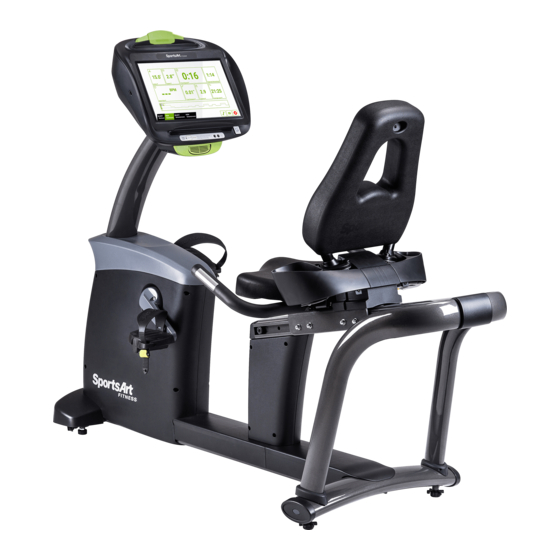
1. iNTROducTiON Congratulations on your purchase of one of the finest exercise products on the market today, the C575U 16” Senza Console upright exercise cycle. Constructed of high quality materials and designed for years of reliable usage, this product was made to become an integral part of your commercial fitness venue. -
Page 5: Safety Precautions
2. SAfETy PREcAuTiONS Your SportsArt bike was designed and built for optimum safety. However certain precautions apply whenever you use your bike. Please read the entire manual before assembly and operation. Also, please note the following safety precautions: ● Please read the instructions carefully and install the bike as instructed. ●... - Page 6 2. SAfETy PREcAuTiONS (cONTiNuEd) ● Children 12 or younger should be supervised to ensure that they do not play with the bike ● Maintenance and repair must be performed by trained service personnel only. Improper maintenance would not only damage the machine, but also may present a danger to the exerciser.
- Page 7 2. SAfETy PREcAuTiONS (cONTiNuEd) If you are a French speaking person in North America, please place the following label contained in the owner’s manual on the console as shown. Customers outside of North America will not receive this French warning label.
- Page 8 2. cONSiGNES dE SÉcuRiTÉ iMPORTANTES • Votre vélo SportsArt a été conçu et fabriqué afin d’assurer une sécurité optimale. Cependant certaines précautions s’appliquent chaque fois que vous utilisez votre vélo de course. • Lisez entièrement le manuel avant l’assemblage et l’utilisation. Veuillez aussi noter les consignes de sécurité...
- Page 9 2. cONSiGNES dE SÉcuRiTÉ (SuiTE) Ce vélo n’est pas destiné à être utilisé par des personnes (y compris des enfants) dont les capacités physiques, sensorielles ou mentales sont réduites ou qui ne disposent pas de l’expérience ou du savoir nécessaires, sauf si celles-ci ont au préalable été...
-
Page 10: List Of Parts
3. LiST Of PARTS Assembly Parts Name Qty. No. Name Qty. Pedestal assembly Seat bottom Storage tray Hardware kit Main frame Power cord Pedal set TV Terminal Rear support... - Page 11 3. LiST Of PARTS (cONTiNuEd) components in the Hardware Kit Name Qty. Specification Notes L-shaped Allen wrench L-shaped Allen wrench Double open-end wrench (12*15) Screwdriver handle Green Screwdriver shank Flat and Phillips components on the Product Name Specification Notes Mushroom top inner hex screw M8*L20 and washer Inner hex screw...
-
Page 12: Assemble The Product
4. ASSEMBLE THE PROducT Follow instructions below to assemble this product. Note that in this manual the words “left” and “right” are used to refer to the product and its parts. As such, these designations correspond to the “left” and “right” sides of a per- son in position to exercise on this product. -
Page 13: Step 2 Install The Rear Support
STEP 2 install the Rear Support Please follow steps (a) through (c) to install the rear support. (a) Remove screws (21) from the rear support. (b) Insert the stem of the rear support (A5) into the rear tube of the main frame (A3). -
Page 14: Step 3 Install The Storage Tray
STEP 3 install the Storage Tray Please follow steps (a) through (b) below to install the storage tray. (a) First remove screws (24) from the pedestal (A1). (b) Use these screws (24) to secure the storage tray (A2) onto the pedestal. -
Page 15: Step 4 Install The Pedestal
STEP 4 install the Pedestal Please follow steps (a) through (d) below to install the pedestal assembly.. (a) First pull the front cover (25) off the main frame and then remove screws (22) from the pedestal (A3). (b) Connect the cable in the pedestal (A1) to the cable in the main frame body (A3). -
Page 16: Step 5 Install The Seat Bottom And Pedals
STEP 5 install the Seat Bottom and Pedals Please follow steps (a) through (c) to install the seat bottom and the pedals. (a) First remove screws (23) from the seat bottom (A6). (b) Place the seat bottom (A6) onto its mount on the main frame and then use screws (23) to secure the seat bottom (A6) to the main frame. -
Page 17: Step 6 Move The Product
STEP 6 Move the Product Please follow steps (a) through (c) below to move the bike into place for use. (a) Stand in front of the bike, press one foot on the roller. (b) Put both hands onto the handlebars. (c) Title the bike and roll it into place. -
Page 18: Step 7 Level The Bike
STEP 7 Level the Bike For the user’s safety and the proper functioning of the product, this bike must sit level on a flat floor. If necessary, adjust the levelers by following instruc- tions (a) through (c) below. (a) Loosen the leveler nut. (b) Rotate the leveler foot downward so it firmly touches the floor. -
Page 19: Step 8 Install The Power Cord
STEP 8 install the Power cord (a) First remove screws (26) from the power cord socket on the product. (b) Insert the power cord into place on the product. (c) Secure power cord connector screws (26) and then insert the other end of the power cord (A8) into the appropriate power supply socket in the wall. -
Page 20: Step 9 Tv Terminal And Network
STEP 9 TV Terminal and Network (a) NETWORK: Connect to Ethernet. (b) AV Terminal: Connect to DVD Player or Media Player. (c) TV: Connect to ATV (NTSC or PAL) or DTV. -
Page 21: Step 10 Install The Tv Cable
STEP 10 install the TV cable NTSC system: Directly connect your local area connector as shown. PAL system: Insert NTSC To PAL Adapter (30) as shown and connect to your local area connector. -
Page 22: Step 11 Seat Fore And Aft Adjustment
STEP 11 Seat fore and Aft Adjustment (a) Push the seat adjustment level down to loosen the seat. (b) Push the seat to a suitable position toward the front or toward the back of the unit and then lift the lever up to secure the seat into place. -
Page 23: Step 12 Seat Height Adjustment
STEP 12 Seat Height Adjustment (a) To adjust the seat upward, simply pull the seat upward. (b) To adjust the seat downward, lift the seat adjustment knob and push the seat downward to a suitable position and then release the knob to secure the seat in place. -
Page 24: Understand The C575U 16" Senza Console
5. uNdERSTANd THE SENZA cONSOLE diSPLAy Overview C575U Series 16” Senza Console are designed to help users obtain their fitness goals in a simple and convenient way. Before using the cycle, please familiarize yourself with the functions of this display console to obtain opti- mum benefits and enjoyment from this product. -
Page 25: Operate The Product
6. OPERATE THE PROducT OPERATiON Safety Operating Area (a) Safety clearance required as below shown. Do not allow people to be near this area when operating. (b) Noise emission under load is higher than without load. -
Page 26: Operation Proper Workout Position And Safety Get Off
OPERATiON Proper Workout Position and Safety Get Off (a) User proper workout position as below shown. (b) Over exercise or improper workout position may result in serious injury. (c) User can hold onto handles for stability when getting on or getting off from the right/left side of the elliptical. -
Page 27: Operation Overview
OPERATiON Overview Touch screen design is simple and clear. The screen layout helps users focus on exercise. It provides many workout modes that can help you achieve your fitness goal. The following sections introduce information concerning touch screen operation, the available types of workout, and how to start the workouts. -
Page 28: Operation Start Your (Go) Workout
OPERATiON Startup Screen (continued) No. Name of button function Displays various virtual realities. Touch this screen FEATURE to access the virtual reality training mode 10 GO Touch this button to start workout OPERATiON Start your (GO) Workout By using the (GO) workout, exercise is started in the manual workout mode. The default user age is 35 and default weight is 75 kg (165 lbs). -
Page 29: Operation Workout Programs
OPERATiON Workout Selection (continued) description of icons on the “Select” screen icON description Tap to return startup screen. During exercising, tap it to stop or resume workout. Quick Tools OPERATiON Workout Programs Workout program details are explained below. QuicK START A workout mode option based on time, distance and calories that allows user to start a workout immediately. -
Page 30: Operation Workout Status
OPERATiON Workout Status During the workout, you can select the “VIEW Dashboard” page below the screen to check the exercise status of your workout process. There are a total of 9 status windows for various information views, and you can modify the information display format in the status windows by touching the▼symbol below the status windows. -
Page 31: Operation Select Entertainment
OPERATiON Workout Status (continued) drop down Menu items Symbol default Other Options Calories/Min Calories Calories/Hour Mets Average RPM OPERATiON Select Entertainment You can select the “Select Entertainment” page below the screen, and the available multimedia features will be displayed. The features include TV, In- ternet, SENZA Journeys, Bluetooth Audio, IPTV and AVIN, etc.: the small central window will display the selected multimedia screen immediately. -
Page 32: Operation View Entertainment
OPERATiON View Entertainment The display mode that maximizes the selected multimedia capabilities; in addition to the multimedia display, a sidebar workout information display is also included, so the user can check their current workout status instantly while using the multimedia features. description of icons in the “Entertainment”... -
Page 33: Operation Workout Summary
OPERATiON Workout Summary At the end of a workout or when you press the stop button, the workout sum- mary screen will appear. The screen shows your current workout status. OPERATiON idle Mode When the cycle stops running with no other activity for 2 minutes, the ma- chine will enter the idle mode and the display will randomly show the standby picture. -
Page 34: About Heart Rate Detection
7. ABOuT HEART RATE dETEcTiON Heart rate detection functions are selected at the time of purchase. Not every product has every type of heart rate detection. The following explains factors that influence the performance of two of the most common types of heart rate detection devices. -
Page 35: Guidelines For Exercise
8. GuidELiNES fOR EXERciSE HOW HARd SHOuLd i EXERciSE? Studies show that to benefit from aerobic exercise, people need to maintain a certain heart rate during their workouts. Your heart rate training zone depends on your age and fitness level. The darkened area in the chart to the right represents the recommended heart rate training zone for people of various ages. -
Page 36: Maintenance
9. MAiNTENANcE This section covers maintenance topics, including instructions on replacing a fuse and lubricating the walk belt, along with the presentation of a main- tenance schedule, maintenance task list, one-year maintenance log, and electronics block diagram. MAiNTENANcE Safety Precautions ●... -
Page 37: Maintenance How To Replace A Fuse
MAiNTENANcE How to Replace a fuse If electrical current becomes too high, the fuse breaks. This protects the product. To replace a fuse, follow instructions (a through g) below. (a) Use a tool to press the fuse cap inward. (b) Turn the fuse cap counterclockwise. (c) The fuse cap springs out. -
Page 38: Maintenance Schedule
MAiNTENANcE Schedule Area Week Month Quarter Year Notes Exterior Clean Inspect and secure Screws loose parts Seat back Wipe clean with a and bottom slightly damp towel. Inspect and secure Pedals loose parts... -
Page 39: Maintenance Task List
MAiNTENANcE Task List Like cars, fitness products require maintenance. Regular maintenance ex- tends product life, and failure to maintain products can void the manufac- turer’s warranty. Copy the maintenance log sheet, and record maintenance work for each fitness product. daily tasks 1. -
Page 40: Maintenance One-Year Maintenance Log
MAiNTENANcE One-year Maintenance Log Facility:_______________________ Supervisor:____________________ Product model number:__________ Serial number:_________________ Start date: ____________________ End date:_____________________ daily Tasks Weeks 1-7 Weeks 8-14 Weeks 15-21 Week 22-28 Completed daily Tasks Week 29-35 Week 36-42 Week 43-49 Week 50-52 Completed Weekly Tasks Weeks 1-7 Weeks 8-14 Weeks 15-21 Weeks 22-28... -
Page 41: Accessories
10. AccESSORiES These accessories are related to the functions of this machine. Some are standard and others are optional. The details of each accessory and its function are explained. uSB cHARGER (Standard) The USB charger will provide 5V and 1.5A voltage for charging of smart phone or other devices. - Page 42 AccESSORiES Entertainment cap (a) RFID member card slot: Work with both optional SA WELL+ and ECOFIT member cards. (Not available yet.) (b) Bluetooth/WIFI button: When a smart phone is connected with equipment, press this button to disconnect. Scan the QR code or touch the NFC tag on the console to connect to the equipment again if necessary.
-
Page 43: Appendixes
11. APPENdiXES APPENdiXES Specifications Model c575u 16” L : 1175 mm (46.3”) dimensions W : 585 mm (23”) H : 1410 mm (55.5”) Overall Weight 73 kg (161lbs) Maximum user Weight 150 kg (330 lbs) 100 – 120 V / 60 Hz (USA) Power Requirement 220 –... -
Page 44: Appendixes Electronics Block Diagram
APPENdiXES Electronics Block diagram BT Board Control Board CSAFE Board Main Board TV Board USB Board HRC Board NFC Board Head Phone Board EUP Key Board HTR Board Contact HTR plates Drive Board EUP Board Model no. board Speed sensor Console power board AV Board Fuse... - Page 45 your Authorized distributor...
Need help?
Do you have a question about the C575U-16 and is the answer not in the manual?
Questions and answers