Table of Contents
Advertisement
Quick Links
E874 - 13'' OWNER'S MANUAL CONTENTS
DISCLAIMER ....................................................................................... 3
1. INTRODUCTION ............................................................................. 5
2. SAFETY PRECAUTIONS ................................................................ 6
3. WARNING LABEL POSITION ......................................................... 10
4. LIST OF PARTS ............................................................................. 11
5. ASSEMBLE THE PRODUCT .......................................................... 14
STEP 1 Install the Main Frame ....................................................... 14
STEP 2 Install the Console ............................................................. 17
STEP 3 Install the Outer link pedal arm covers ................................ 18
STEP 4 Install the Front base cover................................................. 19
STEP 5 Install the Pedals ................................................................ 20
STEP 6 Precautions When Installing the Pedals ............................. 21
STEP 7 Move the Elliptical Trainer in Place .................................... 22
STEP 8 Level the Product ............................................................... 23
STEP 9 Power Cord Installation Instructions ................................... 24
STEP 10 TV and Network Function ................................................. 25
STEP 11 Beware of Moving Parts ................................................... 26
STEP 12 Essential Functions Guide ............................................... 27
STEP 13 MAINTENANCE Circuit Breaker ...................................... 28
6. UNDERSTAND THE SENZA CONSOLE ....................................... 29
DISPLAY Overview ......................................................................... 29
DISPLAY Console Panel ................................................................. 29
DISPLAY Specifications .................................................................. 30
DISPLAY Button Function ............................................................... 30
7. OPERATE THE PRODUCT ............................................................ 31
OPERATION Safe Operating Area ................................................. 31
OPERATION Safely Get On/Off ...................................................... 32
OPERATION Proper Workout Position ............................................ 33
OPERATION Start Screen .............................................................. 34
OPERATION GO mode .................................................................. 35
OPERATION Workout Selection ..................................................... 36
OPERATION Workout Status .......................................................... 38
OPERATION Select Entertainment ................................................. 40
OPERATION View Entertainment ................................................... 41
OPERATION Workout Summary ..................................................... 41
OPERATION COOL DOWN ............................................................ 42
OPERATION Idle Mode .................................................................. 42
OPERATION Energy Smart Function .............................................. 42
OPERATION Precautions ............................................................... 42
OPERATION SA WELL+ ................................................................. 43
Advertisement
Table of Contents

Subscribe to Our Youtube Channel
Related Manuals for SportsArt Fitness SENZA E874-13


Summary of Contents for SportsArt Fitness SENZA E874-13
-
Page 1: Table Of Contents
E874 - 13’’ OWNER’S MANUAL CONTENTS DISCLAIMER ..................3 1. INTRODUCTION ................5 2. SAFETY PRECAUTIONS ..............6 3. WARNING LABEL POSITION ............10 4. LIST OF PARTS ................11 5. ASSEMBLE THE PRODUCT ............14 STEP 1 Install the Main Frame ............14 STEP 2 Install the Console ............. - Page 2 E874 - 13’’ OWNER’S MANUAL CONTENTS 8. ABOUT HEART RATE DETECTION ..........44 HEART RATE Telemetry ..............44 HEART RATE Contact ..............44 9. GUIDELINES FOR EXERCISE ............45 10. MAINTENANCE ................46 MAINTENANCE Safety Precautions ..........46 MAINTENANCE Error Messages ............ 47 MAINTENANCE Lubrication ............
-
Page 3: Disclaimer
DISCLAIMER The information in this user manual is subject to change without prior notice. Sports Art Industrial Co., Ltd. makes no representation or warranty of any kind, express or implied, regarding the marketability of this manual, the suitability for a special purpose, or any other matters. SportsArt Industrial Co., Ltd. - Page 4 DISCLAIMER (CONT.) E1. This machine only supports viewing local free TV. E2. This machine may be affected by the local environment, climate, equipment, etc., which may cause poor quality in reception and definition. This machine does not support the installation of 3rd party APP. Standard USB charger: Supports charging of GOOGLE-certified Android mobile phones, and Apple iPhone, iPad, iPad air, and iPad mini.
-
Page 5: Introduction
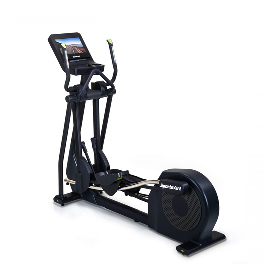
1. INTRODUCTION Congratulations on the purchase of a high quality SportsArt product, the E874-13” Senza Console Elliptical trainer. Constructed of high quality materials and designed for years of reliable performance, this product was made for full commercial use. Before this product is assembled or operated, we recommend that you familiarize yourself with this manual. -
Page 6: Safety Precautions
2. SAFETY PRECAUTIONS This product was designed and built for optimum safety. However certain precautions apply during the use of this product. Please note the following safety precautions: ● To reduce the risk of personal injury, read and understand all the instructions before using this product. - Page 7 2. SAFETY PRECAUTIONS (CONT.) ● Do not use accessories or parts that are not specifically recommended by the manufacturer (SportsArt). Such parts might cause injuries or cause the unit to fail and void the warranty. We will not be responsible for any safety issue that arises due to the misuse of accessories or parts.
- Page 8 2. SAFETY PRECAUTIONS (CONT.) ● This product must be grounded. If it should malfunction or breakdown, Improper grounding can increase the risk of electric shock. The product is equipped with a power cord having an equipment-grounding conductor and a grounding plug. The plug must be inserted into an appropriate outlet that is properly installed and grounded in accordance with all local codes and ordinances.
- Page 9 2. SAFETY PRECAUTIONS (CONT.) MARKINGS CAUTION: ● Read instruction manual before using. ● Do not let children on or near the product. WARNING: ● Heart rate monitoring system may be inaccurate. ● Over exercise may result in serious injury or death. ●...
-
Page 10: Warning Label Position
3. WARNING LABEL POSITION If you are in French-speaking areas in North America, display the warning label on console panel as shown below, or in an obvious location that is visible to the user. NOTE: The label is available exclusively in French-speaking areas in North America. -
Page 11: List Of Parts
4. LIST OF PARTS Assembly Parts Name Qty. No. Name Qty. A1 Main frame Front base cover Left support tube A2 Stationary handlebar Console Right support tube A4 Left/right joint covers A10 Foot pedals A5 Left pedestal cover A11 Pedal bottom covers Outer link pedal arm A6 Right pedestal cover covers... - Page 12 4. LIST OF PARTS (CONTINUED) Hardware Kit Name Qty. Specification Notes Inner hex screw M10*P1.5*L20 Toothed lock washer D20*d10.2*t2.0 Secondary roller axle D9.96*L54 Self-lubricating bushing Secondary roller Stride adjustment linkage cover Hex nut M10*P1.5 Stopper Ø30-30 Round shaped screw cap Mushroom top philips screw M4*L16 Round shaped screw cap...
- Page 13 4. LIST OF PARTS (CONTINUED) Components on the Product Name Specification Notes Hex socket flat head cap screw M10*P1.5*L20 5/16"*L2-1/4" Half Inner hex screw tooth Flat washer D20*d8*t2.0 Mushroom top inner hex screw M8*P1.25*L15 Flat washer D17*d8.3*t2 Inner hex screw M6*P1.0*L15 Handlebar washer D20*d7*t2...
-
Page 14: Assemble The Product
5. ASSEMBLE THE PRODUCT STEP 1 Install the Main Frame (1) Remove all packaging material and place the main frame on the carton base. (2) Lift the console mast into upright position, and then tighten the following screws in sequence: screw (33) in (area D), screw (10) in (area A), and screws (10) in (area B,C). - Page 15 STEP 1 Install the Main Frame (Cont.) (5-1) Slip the glide rail into the pedal carriage and lower swing arm, and then install the secondary roller (11) to the bottom of glide rail. (NOTE: Insert the axle toward inner side from outer side) (5-2) Insert the axle shaft into housing on the pedal arm, then tighten screw (34) to secure the assembly, and put the stride adjustment linkage cover on.
- Page 16 STEP 1 Install the Main Frame (Cont.) (6-1) Insert left and right support tubes (A8)(A9) into the axle area and base, and loosely secure them into place with screws (35) (36) (6-2) Install the stationary handlebar (A2) to the left/right support tube and using screw (37) to secure the assembly.
-
Page 17: Step 2 Install The Console
STEP 2 Install the Console (1) Remove the following parts from the console(A3): anti-slip pad (51), screws (52)(53), and bottle holder (54). (2) Secure the console (A3) to the main frame (A1) with pre-installed screw (39). (3) Remove the rear cover (55) and then connect the cables of the main frame (A1) to the cables of the console (A3). -
Page 18: Step 3 Install The Outer Link Pedal Arm Covers
STEP 3 Install the Outer link pedal arm covers (1) Rotate the pedal arm to the position shown in the figure below, then put on cover B and rotate it 270 degrees clockwise. (2) Snap cover B and cover C together, and rotate the pedal arm until (area A) is easily accessed, then tighten screws (16)(17). -
Page 19: Step 4 Install The Front Base Cover
STEP 4 Install the Front base cover Secure left/right pedestal cover(A5)(A6) to the main frame using screw (15), then put on the round shaped screw cap (15) and the front base cover (17). NOTE: install the ground wire first before putting the front base cover on. -
Page 20: Step 5 Install The Pedals
STEP 5 Install the Pedals (1) Secure the pedal bottom cover (A11) to the main frame using screws (40), and then put on the round shaped screw cap (14). (2) Pull up part A, and then secure the foot pedal (A10) onto its mount on the pedal carriage (A1) using screw (41). -
Page 21: Step 6 Precautions When Installing The Pedals
STEP 6 Precautions When Installing the Pedals (1) Make sure the 2 nibs in (area L) are pushed into the holes on the foot pedal. (2) Tighten screws (m1), then push the 2 nibs in (area M) into the holes on the foot pedal. -
Page 22: Step 7 Move The Elliptical Trainer In Place
STEP 7 Move the Elliptical Trainer in Place Grip and lift the main base of the elliptical trainer, and then move it to the desired location. Be careful not to pinch your fingers when you put down the elliptical trainer. -
Page 23: Step 8 Level The Product
STEP 8 Level the Product (1) If your workout area is uneven, or if the rail assembly is slightly off the floor, loosen the locking nut at the back of the equipment and adjust the leveler until it is evenly balanced in contact with the floor, then tighten up the locking screw. -
Page 24: Step 9 Power Cord Installation Instructions
STEP 9 Power Cord Installation Instructions (1) Remove the screw (42) from the base of the main frame. (2) Insert the power cord plug into the connector on the product. (3) Plug the power cord (A13) into the outlet and secure the power cord plug in place with the removed screw (42). -
Page 25: Step 10 Tv And Network Function
STEP 10 TV and Network Function (a) NETWORK: Connect to the Ethernet with the external network signal. (b) AV PORT: Support external DVD PLAYER or other multimedia players using AV output signal. (c) Support MYE Wireless TV Audio_Channel Receiver, and the other equipment that conform to the CSAFE specification. -
Page 26: Step 11 Beware Of Moving Parts
STEP 11 Beware of Moving Parts This product has moving parts that could be a danger to people and animals. During use, do not put hands or other objects into the stride adjustment slot, the rear cover opening, or other areas in which such action might present a hazard. -
Page 27: Step 12 Essential Functions Guide
STEP 12 Essential Functions Guide LENGTH: Adjust the distance between two successive placements of the same foot. RESISTANCE: Adjust the weight or force you need to place on the pedals to push them. -
Page 28: Step 13 Maintenance Circuit Breaker
STEP 13 MAINTENANCE Circuit Breaker (a) A circuit breaker is an automatically operated electrical switch designed to protect an electrical circuit from damage caused by overcurrent/ overload or short circuit. A spring located under the push button causes the button at area D to lift up and the breaker to trip as shown. (b) After the fault is repaired by qualified technicians, press the push button to reset circuit breaker to resume normal operation as shown. -
Page 29: Understand The Senza Console
6. UNDERSTAND THE SENZA CONSOLE DISPLAY Overview E874 Series 13” Senza Console is designed to help users obtain their fitness goals in a simple and convenient way. Before using the elliptical trainer, please familiarize yourself with the functions of this display console to obtain optimum benefits and enjoyment from this product. -
Page 30: Display Specifications
DISPLAY Specifications Parameter Spec. RESISTANCE 1-40 Stride Length 17-29 inch (450-730mm) Total Stride 0-9999 steps SPEED 0.0-99.9 MPH or 0.0-99.9 KPH TIME 0:00-600:00 min HEART RATE 35-220 bpm DISTANCE 0.00-9999 Mile/Km CALORIES 0-9999 Cal 5-150 steps/ min Calories /Hour 0-9999 Cal/Hour Mets 0-99.99 QUICK START, GOALS, PLATEAU, INTERVAL,... -
Page 31: Operate The Product
7. OPERATE THE PRODUCT OPERATION Safe Operating Area (a) Safety clearance required as shown below. Do not allow people to be near this area when operating. (b) Noise emission under load is higher than without load. 600mm(23.6") -
Page 32: Operation Safely Get On/Off
OPERATION Safely Get On/Off (a) Place your feet on floor and then hold the handles to steady self while stepping on the pedals as shown below. (b) Wait until pedals come to a complete stop and then hold onto handles for stability while carefully stepping off the elliptical. -
Page 33: Operation Proper Workout Position
OPERATION Proper Workout Position (a) Proper workout position for user is shown below. (b) Over exercising or improper workout form may result in serious injury. (c) User can hold onto handles for stability when getting on or getting off from the right/left side of the elliptical. (d) This product is intended to exercise arms, legs, and the cardiovascular system. -
Page 34: Operation Start Screen
OPERATION Start Screen Turn on the power or press the wake-up key to go to start screen. Description of start screen buttons: Name of button Function Date and Time Displays the current time and date Touch this button to access workout pro- SELECT gram selection SA WELL+... -
Page 35: Operation Go Mode
OPERATION GO mode Press <GO>key, then the screen will start counting down by showing 3,2,1,0,GO on the display. The product will start with the default setting of 35 years old, weight 75 kg (165 lbs) and the PROGRAM will start in quick start – time mode, with resistance level 1. -
Page 36: Operation Workout Selection
OPERATION Workout Selection 1. At start screen, touch the Select icon to access“SELECT WORKOUT”. Select workouts on the screen: By swiping with your fingers, you can move between the workout options on the screen. The workout options are as follows: QUICK START, GOALS, PLATEAU, INTERVAL, SENZA JOURNEYS, FAT BURN, VARI STRIDE, WATT, HEART RATE and FITNESS TEST. - Page 37 OPERATION Workout Selection (Cont.) 2. Workout selection can choose your own workout programs, here are some details explained below. QUICK START A workout mode option based on time, distance and calories that allows user to start a workout immediately. GOALS Set your own time, distance, and calorie goal.
-
Page 38: Operation Workout Status
OPERATION Workout Status During the workout, you can select the “VIEW Dashboard” page below the screen to check the exercise status of your workout process. There are a total of 9 status windows for various information views, and you can modify the information display format in the status windows by touching the▼symbol below the status windows. - Page 39 OPERATION Workout Status (Cont.) Drop down Menu items Symbol Default Other Options Total Distance Distance Remaining Calories/Min Calories/Hour Calories Mets Set Target Calories Average SPM Change Speed...
-
Page 40: Operation Select Entertainment
OPERATION Select Entertainment You can select the “Select Entertainment” page below the screen, and the available multimedia features will be displayed. The features include TV, Internet, SENZA Journeys, Bluetooth Audio, USB Audio, USB Video, IPTV and AVIN, ANYCast, Youtube, Netflix, HDMI(optional) etc.: the small central window will display the selected multimedia screen immediately. -
Page 41: Operation View Entertainment
OPERATION View Entertainment The console displays the media window in maximum frame size. If you want to check your workout status, simply tap the taskbar at the bottom of the screen. That way, you can evaluate your training status and adjust the workload accordingly. -
Page 42: Operation Cool Down
OPERATION COOL DOWN When finishing your target program (time, distance, calories) or when pressing the key “CoolDown Workout”, display will pop up “GOING TO COOL DOWN”, then the machine will enter a two-minute cool down period and count down from 2:00 to 0:00. OPERATION Idle Mode When the elliptical trainer stops running with no other activity for 2 minutes,... -
Page 43: Operation Sa Well
OPERATION SA WELL+ Tap SA WELL+ to enter SA WELL+ Login page. First time user must create an user account with SA WELL+ App. After signing up, user information will be saved into the account. Login to your SA Well+ account to track your workouts. This will also allow you to download a created custom workout to the machine. -
Page 44: About Heart Rate Detection
8. ABOUT HEART RATE DETECTION Heart rate detection functions are selected at the time of purchase. Not every product has every type of heart rate detection. The following explains factors that influence the performance of two of the most common types of heart rate detection devices. -
Page 45: Guidelines For Exercise
9. GUIDELINES FOR EXERCISE HOW HARD SHOULD I EXERCISE? Studies show that to benefit from aerobic exercise, people need to maintain a certain heart rate during their workouts. Your heart rate training zone depends on your age and fitness level. The darkened area in the chart to the right represents the recommended heart rate training zone for people of various ages. -
Page 46: Maintenance
10. MAINTENANCE Maintenance topics are presented below in the following order: error mes- sages, lubrication of the shoulder area, lubrication of the stride area, glide rail cleaning, maintenance schedule, task list, one-year maintenance log, and wiring diagram. MAINTENANCE Safety Precautions ●... -
Page 47: Maintenance Error Messages
MAINTENANCE Error Messages The following messages can appear on this product for diagnostic purposes. ERROR 7 L, ERROR 7 R & ERROR 7 R/L - Indication: the stride mecha- nism is not calibrated properly. Contact a certified SportsArt technician. The technician will need to either inspect the stride motor or the driver. -
Page 48: Maintenance Lubrication Procedure
MAINTENANCE Lubrication Procedure (a) Push in at point A, and slide upward to remove the lubrication cover. (b) Press the stride up key to adjust the stride to its longest point. Note the grease fitting at area B. (c) Use an automobile grease gun with red lithium grease. Apply the grease to the nozzle on the product. -
Page 49: Maintenance Cleaning The Glide Rails
MAINTENANCE Cleaning the Glide Rails Follow the steps below to clean left and right glide rails on a daily basis: (a) Use a clean, lint-free cloth to wipe dust and debris off the glide rails. (b) Test the glide rails to ensure they move easily and smoothly. (c) Repeat steps (a) and (b) two or three times to ensure smooth movement. -
Page 50: Maintenance Schedule
MAINTENANCE Schedule Area Week Month Quarter Year Notes Exterior Cleanliness inspection ● Inspect and secure loose Screws ● parts Wipe away dirt and Glide rail ● debris. Rollers Apply silicone lubricant.. ● Stride motor Apply bearing grease ● Lubricate with original Cushion ●... -
Page 51: Accessories
11. ACCESSORIES ACCESSORIES Standard USB CHARGER 1. Provides up to 5V, 1.5A of power for charging 2. Let you update all required software drivers for the product. 3. When plug an USB flash drive that contains music or video files in MP3/ MP4 format, the media player will be activated and the playlist will be displayed. -
Page 52: Accessories Option
ACCESSORIES Option SA WELL+ Member System This is designed specially by SportsArt to assist the user in managing their workout history. There are three ways to get connected with the member site: 1. Using a smartphone, connect to the unit via Bluetooth/WIFI and use the SA WELL+ App. -
Page 53: Appendixes
12. APPENDIXES APPENDIXES Specifications Model E874 13’’ L : 2085 mm (82”) Dimensions W : 680 mm (26.8”) H : 1765 mm (69.5”) Overall Weight 144 kg (318 lbs) Maximum User 205 kg (450 lbs) Weight 100 - 120 V , 60Hz , 0.7A (USA) Power Requirement 200 - 240 V , 50Hz , 0.35A (EUROPE) Circuit Breaker... -
Page 54: Appendixes Wiring Diagram
APPENDIXES Wiring Diagram SA WELL Option SA WELL+ Connection SA WELL Board Display Board USB Board HTR Board Control Board WIFI Board TV Board USB Board Bluetooth Board NFC Board EUP Board Headphone Board LENGTH (Left) RESISTANCE (Right) Stepper Motor Contact HTR plates Model no. -
Page 55: Appendixes Exploded Diagrams
APPENDIXES Exploded Diagrams Note: We reserve the right to revise the following diagrams at any time without notice to notify any person of such revisions. Please visit our official website www.gosportsart.com for the latest version. -
Page 56: Appendixes Disassembly
APPENDIXES Disassembly (a) Main Frame (b)Lift Motor Assembly (c)Front Base Cover... - Page 57 Your Authorized Distributor...
Need help?
Do you have a question about the SENZA E874-13 and is the answer not in the manual?
Questions and answers