Table of Contents
Advertisement
Quick Links
Advertisement
Table of Contents

Related Manuals for Beisler 2112-5


Summary of Contents for Beisler 2112-5
- Page 1 Operating Instructions...
- Page 2 IMPORTANT READ CAREFULLY BEFORE USE KEEP FOR FUTURE REFERENCE All rights reserved. Property of Dürkopp Adler AG and protected by copyright. Any reuse of these contents, including extracts, is prohibited without the prior written approval of Dürkopp Adler AG. Copyright © Dürkopp Adler AG 2020...
-
Page 3: Table Of Contents
Activating the needle thread clamp ..........48 Initializing the day counter ............48 Checking the cutters ..............49 5.6.1 Checking the cutters ..............49 5.6.2 Winding the hook thread............. 50 Maintenance ................51 Cleaning ..................52 Lubricating .................. 53 Operating Instructions 2112-5 - 00.0 - 02/2020... - Page 4 Customer Service ............... 71 10.2 Messages of the software............71 10.3 Errors in sewing process ............75 Technical data................77 11.1 Data and characteristic values ........... 77 11.2 Requirements for fault-free operation ......... 77 Operating Instructions 2112-5 - 00.0 - 02/2020...
-
Page 5: About These Instructions
Proper setting Specifies proper setting. Disturbances Specifies the disturbances that can occur from an incorrect adjustment. Cover Specifies which covers must be disassembled in order to access the com- ponents to be set. Operating Instructions 2112-5 - 00.0 - 02/2020... - Page 6 Safety ( p. 7). If no other clear location information is used in a figure, indications of right Location information or left are always from the user's point of view. Operating Instructions 2112-5 - 00.0 - 02/2020...
-
Page 7: Other Documents
Leave machines, equipment and packaging material in the condition in which they were found when the damage was discovered. This will ensure any claims against the transport company. Report all other complaints to Dürkopp Adler immediately after receiving the product. Operating Instructions 2112-5 - 00.0 - 02/2020... - Page 8 About these instructions Operating Instructions 2112-5 - 00.0 - 02/2020...
-
Page 9: Safety
• Setting up the machine/putting the machine into operation • Performing maintenance work and repairs • Performing work on electrical equipment Only authorized persons may work on the machine and must first have understood these instructions. Operating Instructions 2112-5 - 00.0 - 02/2020... -
Page 10: Signal Words And Symbols Used In Warnings
If ignored, environmental damage can result NOTICE (without hazard symbol) If ignored, property damage can result The following symbols indicate the type of danger to personnel: Symbols Symbol Type of danger General Electric shock Operating Instructions 2112-5 - 00.0 - 02/2020... - Page 11 Type and source of danger! Consequences of non-compliance. Measures for avoiding the danger. This is what a warning looks like for a hazard that could result in moderate or minor injury if the warning is ignored. Operating Instructions 2112-5 - 00.0 - 02/2020...
- Page 12 NOTICE Type and source of danger! Consequences of non-compliance. Measures for avoiding the danger. This is what a warning looks like for a hazard that could result in property damage if ignored. Operating Instructions 2112-5 - 00.0 - 02/2020...
-
Page 13: Machine Description
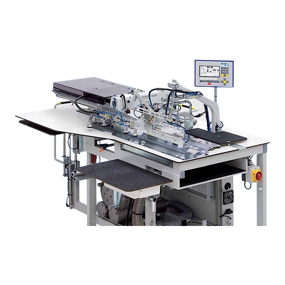
(8) - Control (3) - Guide laser (9) - Pocket bag clamp (4) - Folder (10) - Main clamp (5) - Control panel (11) - Transport stamp (6) - Pick-up plate (12) - Stacker Operating Instructions 2112-5 - 00.0 - 02/2020... -
Page 14: Proper Use
DIN EN 60204-31. Only authorized persons may work on the machine. Dürkopp Adler cannot be held liable for damages resulting from improper use. Operating Instructions 2112-5 - 00.0 - 02/2020... -
Page 15: Declaration Of Conformity
Machine description 3.3 Declaration of Conformity The machine complies with European regulations ensuring health, safety, and environmental protection as specified in the declaration of conformity or in the declaration of incorporation. Operating Instructions 2112-5 - 00.0 - 02/2020... - Page 16 Machine description Operating Instructions 2112-5 - 00.0 - 02/2020...
-
Page 17: Operation
If the machine is prepared for the on-site vacuum supply system, the on- site vacuum hose (4) must be connected to the sleeve (2) of the vacuum valve (3). To switch off the machine: 1. Turn the main switch (5) to the 0 position. Operating Instructions 2112-5 - 00.0 - 02/2020... -
Page 18: Operating The Machine Head
• Flat sewing of the zipper fly onto the front trouser component (right fly piece for men’s trousers, left fly piece for ladies’ trousers) • Lapping and edge folding of the wing pockets on the front trouser component Operating Instructions 2112-5 - 00.0 - 02/2020... -
Page 19: Sewing On The Pocket Facing
The adjusting wheel is continuously adjustable. The stitch width can be set to 4 different levels at the revolver (1), see chap- ter Quick stitch width adjustment ( p. 32). Operating Instructions 2112-5 - 00.0 - 02/2020... - Page 20 The pocket facing (4) is lined up at the stop rail (3) of the pick-up plate (6). The exact alignment to the pocket bag (7) is indicated by a marking (5) on the pick-up plate. Operating Instructions 2112-5 - 00.0 - 02/2020...
- Page 21 The pocket bag is lined up within the operating range of the pocket bag clamp (10). The exact position to the pocket facing (4) is determined by a marking (9) on the working plate. Operating Instructions 2112-5 - 00.0 - 02/2020...
- Page 22 The sliding table (12) then moves backward, and the sewing pieces (15) fall onto the lifting table (14) where they are stacked. The lifting table (14) is lowered automatically by photocell control or in pre- set steps in accordance with the input quantities. Operating Instructions 2112-5 - 00.0 - 02/2020...
-
Page 23: Lapping The Left Fly Piece To The Left Trouser Component
The cutter (4) of the working plate opens, the cutter (6) is passive and remains concealed in the working plate. The positioning lamps (3) make it easier to line up the gusset of the left trouser component with the cutter (4). Operating Instructions 2112-5 - 00.0 - 02/2020... - Page 24 (5) onto the left trouser component (3). While the folder (6) moves left to the working plate, the left trouser compo- nent (3) is incised by the cutter (2). Operating Instructions 2112-5 - 00.0 - 02/2020...
- Page 25 The reel stand can hold 2 thread reels. After the sewing process, the trouser component (2) is blown off the work- table by the compressed air device (3). Operating Instructions 2112-5 - 00.0 - 02/2020...
-
Page 26: Sewing The Right Fly Piece Onto The Right Trouser Component
The right trouser component (6) is aligned with the gusset at the cutter (4) and parallel to the pick-up plate (5) and the folder (1) at the red marking (7) of the guide laser (8). Operating Instructions 2112-5 - 00.0 - 02/2020... - Page 27 After the cutter has made the incision, the stop (9) swivels to the right trouser component. The right fly piece (11) is lined up directly at the stop rail (10) and flush with the right trouser component. Operating Instructions 2112-5 - 00.0 - 02/2020...
- Page 28 The reel stand can hold 2 thread reels. After the sewing process, the trouser component (6) is blown off the worktable by the compressed air device (13). Operating Instructions 2112-5 - 00.0 - 02/2020...
-
Page 29: Lapping The Wing Pocket To The Left Trouser Component
The left trouser component (6) is aligned with the gusset at the cutter (5) and parallel to the pick-up plate (11) and the folder (1) at the red marking (3) of the guide laser. Operating Instructions 2112-5 - 00.0 - 02/2020... - Page 30 Fig. 15: Lapping the left wing pocket to the left trouser component (3), sewing the left wing pocket to the trouser component ⑬ ⑭ ⑮ ⑯ (13) - Sewing head (15) - Sewing pieces (14) - Compressed air device (16) - Main clamp Operating Instructions 2112-5 - 00.0 - 02/2020...
-
Page 31: Lapping The Right Wing Pocket To The Right Trouser Component
The facing (9) of the wing pocket (1) is lined up at the stop rail (11) of the pick-up plate (10). The exact position to the cutter (6) is marked by the gusset in the facing (9). Operating Instructions 2112-5 - 00.0 - 02/2020... - Page 32 (1) onto the trouser component (5). While the folder (2) moves left to the working plate, the right trouser component (5) is incised by the cutter (3). Operating Instructions 2112-5 - 00.0 - 02/2020...
- Page 33 The main clamp (15) transports the sewing pieces on the working plate from the loading station to the sewing head (12). After the sewing process, the sewing pieces (13) are blown off the worktable by the compressed air device (14). Operating Instructions 2112-5 - 00.0 - 02/2020...
-
Page 34: Quick Stitch Width Adjustment (Stitch Width Adjustment)
To change the preset stitch widths: 1. Turn the adjusting wheel (2) at the pick-up plate. • To set a greater stitch width: turn clockwise • To set a smaller stitch width: turn counterclockwise Operating Instructions 2112-5 - 00.0 - 02/2020... -
Page 35: Controlling The Machine Cycle
NEVER allow optical equipment such as burning glasses or lenses to interfere with the laser beam path. Fig. 20: Controlling the machine cycle ① ② (1) - Pedal zipper fly clamp (2) - Pedal machine cycle Operating Instructions 2112-5 - 00.0 - 02/2020... -
Page 36: Controlling The Machine Cycle In Mode 00
If the fully automatic machine cycle was started, the next sewing pieces can be lined up already. The Machine cycle pedal remains deactivated until the main clamp reach- es its start position. After that, the next machine cycle can be started. Operating Instructions 2112-5 - 00.0 - 02/2020... -
Page 37: Controlling The Machine Cycle In Mode 01
When the sewing pieces have been transported to the sewing head, the next pocket facing can be lined up. The Machine cycle pedal remains deactivated until the main clamp reach- es its start position. After that, the next machine cycle can be started. Operating Instructions 2112-5 - 00.0 - 02/2020... -
Page 38: Controlling The Machine Cycle In Mode 02
After any work step, the further machine cycle can be continued automatically. To control the machine cycle in Mode 03: 1. Press the Machine cycle pedal and hold it down. The further machine cycle is fully automatic. Operating Instructions 2112-5 - 00.0 - 02/2020... -
Page 39: Controlling The Machine Cycle In Mode 04
If the automatic machine cycle was started, the next sewing pieces can be lined up already. The Machine cycle pedal remains deactivated until the main clamp reach- es its start position. After that, the next machine cycle can be started. Operating Instructions 2112-5 - 00.0 - 02/2020... -
Page 40: Controlling The Machine Cycle In Mode 05
If the automatic machine cycle was started, the next sewing pieces can be lined up already. The Machine cycle pedal remains deactivated until the main clamp reach- es its start position. After that, the next machine cycle can be started. Operating Instructions 2112-5 - 00.0 - 02/2020... -
Page 41: Controlling The Machine Cycle In Mode 06
If the automatic machine cycle was started, the next sewing pieces can be lined up already. The Machine cycle pedal remains deactivated until the main clamp reach- es its start position. After that, the next machine cycle can be started. Operating Instructions 2112-5 - 00.0 - 02/2020... -
Page 42: Controlling The Machine Cycle In Mode 07
If the automatic machine cycle was started, the next sewing pieces can be lined up already. The Machine cycle pedal remains deactivated until the main clamp reach- es its start position. After that, the next machine cycle can be started. Operating Instructions 2112-5 - 00.0 - 02/2020... -
Page 43: Initializing The Loading Process
To restart the machine after a program stop, all functions must be reset, and the machine cycle must be returned to the zero position. To reset all functions: 1. Press the STOP key 2 times. The control program performs a reset. Operating Instructions 2112-5 - 00.0 - 02/2020... -
Page 44: Standard Sewing Programs
Manual seam without folder station → Close edge → Edge via photocell Seam program M 02 M02: 11 Lapping of the left fly piece M02: 12 Sewing on the right fly piece (option) Operating Instructions 2112-5 - 00.0 - 02/2020... - Page 45 Operation Factory-programmed seam programs Seam program M 03 M03: 15 Lapping of the RIGHT wing pocket (option) M03: 16 Lapping of the LEFT wing pocket (option) Operating Instructions 2112-5 - 00.0 - 02/2020...
- Page 46 Operation Operating Instructions 2112-5 - 00.0 - 02/2020...
-
Page 47: Programming
The memory is con- nected at the corresponding port (8). If the Program STOP key (6) is pressed during machine operation, all ma- chine movements and the sewing process are stopped. Operating Instructions 2112-5 - 00.0 - 02/2020... -
Page 48: Selecting A Seam Program
Seam programs are stored in the memory (M) where up to 50 seam programs (M01 - M50) can be programmed. Each seam program (1) can be assigned up to 6 seam numbers (01 - 06). The 6 seams are distinguished by their control functions. Operating Instructions 2112-5 - 00.0 - 02/2020... -
Page 49: Activating Additional Seam Numbers
To lower and raise the lifting table: 1. Open the submenu Lifting table and press the F4 key. To move the sliding table forward or back: 1. Open the submenu Sliding table and press the F5 key. Operating Instructions 2112-5 - 00.0 - 02/2020... -
Page 50: Activating The Needle Thread Clamp
F6 key. The day counter has been reset to zero. 4. Return to the start level. 5. Press the F1 key. The display shows the message PART: 0000. Operating Instructions 2112-5 - 00.0 - 02/2020... -
Page 51: Checking The Cutters
The cutter performs a cutting movement. 8. Press the Pick-up plate cutter (left wing pocket/right icon. fly piece for ladies’ trousers) 9. Press the F7 key. The cutter performs a cutting movement. Operating Instructions 2112-5 - 00.0 - 02/2020... -
Page 52: Winding The Hook Thread
The display shows the icons of the functions that can be selected on this level: 2. Open the submenu Bobbin and press the F8 key. The bobbin thread is wound on. Operating Instructions 2112-5 - 00.0 - 02/2020... -
Page 53: Maintenance
Operating hours Cleaning Cleaning the machine head Lubricating Lubricating the clamp rail Servicing the pneumatic system Adjusting the operating pressure Draining the water-oil mixture Cleaning the filter element Operating Instructions 2112-5 - 00.0 - 02/2020... -
Page 54: Cleaning
3. Using a compressed air gun, blow off dust and thread residues at the sewing head, at the working plate, at the main clamp and at the linear rail. 4. Wipe machine parts dry using a dry, clean cloth. Operating Instructions 2112-5 - 00.0 - 02/2020... -
Page 55: Lubricating
Dispose of used oil and oily machine parts in accordance with national regulations. Lubricating the clamp rail To lubricate the clamp rail: 1. Switch off the machine. 2. Wipe off the clamp rail using a clean, oil-saturated cloth. Operating Instructions 2112-5 - 00.0 - 02/2020... -
Page 56: Servicing The Pneumatic System
2. Turn the pressure regulator until the pressure gage (2) indicates the proper setting: • Increase pressure = turn clockwise • Reduce pressure = turn counterclockwise 3. Push the pressure regulator (1) down. Operating Instructions 2112-5 - 00.0 - 02/2020... -
Page 57: Draining The Water-Oil Mixture
2. Place the vessel under the drain screw (3). 3. Loosen the drain screw (3) completely. 4. Allow the water-oil mixture to drain into the vessel. 5. Tighten the drain screw (3). 6. Connect the machine to the compressed air supply. Operating Instructions 2112-5 - 00.0 - 02/2020... -
Page 58: Cleaning The Filter Element
6. Wash out the filter tray using benzine. 7. Tighten the filter element (1). 8. Tighten the collection tray (2). 9. Tighten the drain screw (3). 10. Connect the machine to the compressed air supply. Operating Instructions 2112-5 - 00.0 - 02/2020... -
Page 59: Parts List
Maintenance 6.4 Parts list A parts list can be ordered from Dürkopp Adler. Or visit our website for further information at: www.duerkopp-adler.com Operating Instructions 2112-5 - 00.0 - 02/2020... - Page 60 Maintenance Operating Instructions 2112-5 - 00.0 - 02/2020...
-
Page 61: Setup
The scope of delivery depends on your specific order. Check that the scope of delivery is correct after taking delivery. 7.2 Removing the transport locks Remove all transport locks before setting up the machine. Operating Instructions 2112-5 - 00.0 - 02/2020... -
Page 62: Aligning The Stand
Fig. 26: Aligning the stand ① ② ③ ④ ⑤ (1) - Screw (4) - Table foot (2) - Screw (5) - Counternut (3) - Table leg Operating Instructions 2112-5 - 00.0 - 02/2020... -
Page 63: Electrical Connection
The cables and plugs as well as the pedals of the machine have already been fully installed. To establish the electrical connection: 1. Connect the machine to the power supply. Operating Instructions 2112-5 - 00.0 - 02/2020... -
Page 64: Pneumatic Connection
The supply pressure must lie between 8 and 10 bar. 7.5.1 Assembling the compressed air maintenance unit Fig. 27: Assembling the compressed air maintenance unit ① (1) - Pressure hose with push-in plug Operating Instructions 2112-5 - 00.0 - 02/2020... -
Page 65: Adjusting The Operating Pressure
2. Turn the pressure regulator until the pressure gage (2) indicates the proper setting: • Increase pressure = turn clockwise • Reduce pressure = turn counterclockwise 3. Push the pressure regulator (1) down. Operating Instructions 2112-5 - 00.0 - 02/2020... -
Page 66: Connecting The Vacuum Device
• Hose clamp with an internal diameter of 1¼ ’’ Fig. 29: Connecting the vacuum device ① ② ③ ④ (1) - Sleeve (3) - Vacuum valve (2) - Vacuum hose (4) - Vacuum hose Operating Instructions 2112-5 - 00.0 - 02/2020... -
Page 67: Performing A Test Run
The control must switch off. 5. Check the function of the key Program STOP. Start a machine cycle and press the key. All operational movements of the clamp and of the sewing head must stop. Operating Instructions 2112-5 - 00.0 - 02/2020... - Page 68 Setup Operating Instructions 2112-5 - 00.0 - 02/2020...
-
Page 69: Decommissioning
5. Cover the control panel to protect it from soiling. 6. Cover the control to protect it from soiling. 7. Cover the entire machine if possible to protect it from contamination and damage. Operating Instructions 2112-5 - 00.0 - 02/2020... - Page 70 Decommissioning Operating Instructions 2112-5 - 00.0 - 02/2020...
-
Page 71: Disposal
When disposing of the machine, be aware that it consists of a range of different materials (steel, plastic, electronic components, etc.). Follow the national regulations when disposing these materials. Operating Instructions 2112-5 - 00.0 - 02/2020... - Page 72 Disposal Operating Instructions 2112-5 - 00.0 - 02/2020...
-
Page 73: Troubleshooting
I/O module Error 06 Clamp slide not positioned Check sensor connection Step pulses not valid correctly to clamp motor; check connecting cable between adapter board 9020020 and I/O module 9020013; replace adapter board 9020020 Operating Instructions 2112-5 - 00.0 - 02/2020... - Page 74 Error 16 ES08 (folder at left stop) Check ES08 (input); check Folder not left does not switch or switches mechanical components for too late easy movement Operating Instructions 2112-5 - 00.0 - 02/2020...
- Page 75 Adjust photocell sensitivity; No part illuminated during insertion input test 21 Error 42 Photocell FZ21 does not Seam distance too long; Photocell not lighted detect seam end adjust photocell sensitivity; input test 21 Operating Instructions 2112-5 - 00.0 - 02/2020...
- Page 76 21 insertion Errors 45 - 48 Internal hardware error Replace 9020020 I/O DAC, ULN, 485, RES during data transmission to adapter board 9020020 Error 56 Error in 3-phase stepper motor-Power amplifier D900 Operating Instructions 2112-5 - 00.0 - 02/2020...
-
Page 77: Errors In Sewing Process
Check the assembly of the reel assembled incorrectly stand Thread tensions are too Check thread tensions tight Throat plate, hook or Have parts reworked by qualified spread have been specialists damaged by the needle Operating Instructions 2112-5 - 00.0 - 02/2020... - Page 78 Needle thread and hook Check threading path thread have not been threaded correctly Needle breakage Needle thickness is Use recommended needle unsuitable for the sewing thickness material or the thread Operating Instructions 2112-5 - 00.0 - 02/2020...
-
Page 79: Technical Data
Mains frequency [Hz] 50/60 Operating pressure [bar] Length [mm] 1750 Width [mm] 1450 Height [mm] 1700 Weight [kg] 11.2 Requirements for fault-free operation Compressed air quality must conform to ISO 8573-1: 2010 [7:4:4]. Operating Instructions 2112-5 - 00.0 - 02/2020... - Page 80 Technical data Operating Instructions 2112-5 - 00.0 - 02/2020...
- Page 82 DÜRKOPP ADLER AG Potsdamer Straße 190 33719 Bielefeld GERMANY Phone +49 (0) 521 / 925-00 service@duerkopp-adler.com E-mail www.duerkopp-adler.com...
Need help?
Do you have a question about the 2112-5 and is the answer not in the manual?
Questions and answers