Chapters
Table of Contents

Related Manuals for Beisler 100/68


Summary of Contents for Beisler 100/68
- Page 1 100/68 Universal Piped-Pocket-Sewing unit Operating instructions Assembly instructions Service instructions Programming instructions Ausgabe / Edition: 11/2007 Printed in Federal Republic of Germany Teile-Nr.:/Part-No.:DOC000045...
- Page 3 Foreword This instruction manual is intended to help the user to become familiar with the machine and take advantage of its application possibilities in accordance with the recommendations. The instruction manual contains important information on how to operate the machine securely, properly and economically. Observation of the instructions eliminates danger, reduces costs for repair and down-times, and increases the reliability and ute of the machine.
-
Page 4: General Safety Instructions
General safety instructions The non-observance ot the following satety instructions can cause bodily injuries or damages to the machine. The machine must only be commissioned in full knowledge of the instruction book and operated by persons with appropriate training. Before putting into service also read the safety rules and instructions of the motor supplier. -
Page 5: Table Of Contents
Index Page: Part 1: Operating instructions 100/68 Description of product ..........3 Description of proper use . -
Page 7: Description Of Product
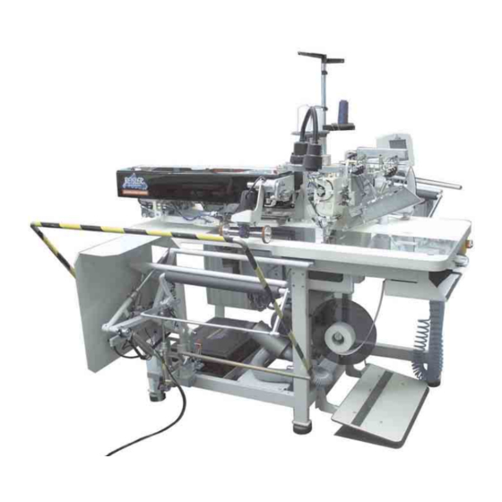
Description of product Description of proper use The Beisler 100/68 is a sewing unit which can properly be used for sewing light to medium-weight material. Such material is, as a rule, made of textile fibres or leather. These materials are used in the garment industry. -
Page 8: Technical Data
Sewing equipment and folders Please see parts list of cl. 100/68 for details concerning sewing equipment and folders for the various applications or contact the Beisler company. Technical data Needle system: 2134-35... -
Page 9: Operating
Operating Swivelling the folding station aside For work at the sewing point (threading the needle threads, needle change etc.) the entire folding station with folder and laser lamps can be swivelled to the right. – Swivel the entire folding station 1 with folder to the right. The sewing point is freely accessible. -
Page 10: Removing The Fabric Sliding Sheet
Removing the fabric sliding sheet Caution: Risk of injury! Switch the main switch off. Remove the fabric sliding sheet only with the sewing unit switched off. – Switch the main switch off For changing the hook thread bobbins: – Lift the fabric sliding sheet 2 at/with the pin 1 and swivel it to the left. -
Page 11: Needles And Threads
Needles and threads Needle system: 2134-85 Recommended needle size: Nm 90 for thin material Nm 100 for medium-weight material Nm 110 for heavy-weight material High sewing security and good sewability are achieved with the following core threads: – Two-ply polyester endless polyester core-spun (e.g. - Page 12 Needle change Caution: Risk of injury! Switch the main switch off. Change the needles only when the main switch is switched off. Risk of cuts! Do not reach into the area of the centre knife 3 when changing the needles. –...
-
Page 13: Threading The Needle Thread
Threading the needle thread Caution: Risk of injury! Switch the main switch off. Thread the needle threads only with the sewing unit switched off. See the illustration for threading the needle threads. -
Page 14: Winding Up The Hook Thread
Winding up the hook thread The separate winder allows to wind up up the hook threads independent of the sewing process. – Remove thread remainders from the bobbin hubs before winding – Put the thread reel on the thread reel holder. –... -
Page 15: Remaining Thread Monitor
Remaining thread monitor The remaining thread monitor supervises the left and right hook thread bobbin with the infrared reflected light barriers 1 and 2. – When the bobbin is empty, the light beam emitted by light barrier 1 or 2 is reflected at the free reflecting surface 3 of the bobbin hub. –... -
Page 16: Slanted Pocket Opening (Optional)
Slanted pocket opening (optional) The 100/68 is optionally equipped with an automatic corner knife station guaranteeing a precise incision of the corners of slanted pockets. For this purpose the machine head is equipped with disengageable needle bars. Corner knife station The adjustment of the corner knives as to the pocket length is programmable and is realized by a step motor. - Page 17 Swivelling the corner knife station in – Swivel the corner knife station 1 back under the sewing unit. – Pull catch 2 down. – Swivel the corner knife station 1 in completely. – Release catch 2. ATTENTION: Risk of breakage! The holder 2 must snap in audibly.
-
Page 18: Switching On - Starting The Sewing Process - Program Stop - Switching Off
Switching on - Starting the sewing process - Program stop - Switching off Switching on – switch the main switch 1 on (turn in clockwise direction). The control loads the machine program. The start screen appears in the display of the control panel and indicates the following message: –... -
Page 19: Reference Position
Reference position Reference position The reference position is necessary to reach a defined initial position. When the sewing unit is switched on, the control checks whether the transport carriage is in its rear end position. If this is not the case, the display shows the following message: Caution: Risk of injury ! Risk of bruises between folder and deposit table. -
Page 20: Program Stop
Program stop For an immediate switch-off of the sewing unit in case of operating errors, needle breakage, material accumulation etc. the safety system of the 100/68 will react as follows: – Press program stop 1. The sewing process is stopped immediately. Switching off –... -
Page 21: Working Methods
Working methods The individual working methods for trousers and men’s jackets are described on the following pages. The description is structured as follows: Feeding positions This item indicates the feeding points for the different workpieces (e.g. left and right parts). Aligning the positioning aids Here you will find a description how to adjust and align the positioning aids (e.g. -
Page 22: Working Method "Production Of Trousers
Working method “Production of trousers” Possible processing variants – Front trousers pockets with pocket bag positioned underneath – Hind trousers pockets with or without flap, with pocket bag positioned underneath – Hind trousers pockets with or without flap, with automatically fed reinforcement strip Feeding method Example: Hind trousers without flap, with pocket bag positioned... -
Page 24: Working Method "Breast Welt Pocket
Working method “Breast welt pocket” Processing patterned or plain-coloured fabrics When processing plain-coloured fabrics it is not necessary to align men’s jacket fronts and breast welts as per pattern. Thus, plain-coloured fabrics can be processed more quickly. - Align positioning aids Feeding method Example: Men’s jacket front with breast welt pocket, patterned fabric 1st step:... -
Page 26: Quick Clamp Adjustment And Folder Monitoring
Quick clamp adjustment and folder monitoring The lateral position of the transport clamps is influenced by the solenoid switches SC103 and SC106. According to the equipment the magnets are fitted on the folders in different positions. Depending on the selected folder the clamps are adjusted automatically. -
Page 27: Function And Operation Of The Optional Equipment
Function and operation of the optional equipment This chapter describes the function and operation of the most important optional equipment. Tape feeding unit with automatic trimming and tape monitor The step motor- and length-controlled tape feed with automatic trimming transports the reinforcement strip under the pocket opening and cuts it off at the seam end (e.g. - Page 29 Inserting the reinforcement strip – Put roll 1 on the tape roll holder 2. The full roll must rotate in the indicated arrow direction (counter-clockwise) when unwinding. – Guide the reinforcement strip via guide 5. – Swivel the fabric sliding sheet 9 aside. –...
-
Page 30: Endless Zipper Device
Endless zipper device Function When the zipper halves are pulled by the transport clamps during the sewing process, the feed rod 6 is pulled upwards by the zipper getting shorter. The feed rod switches the zipper feed on and the drive rollers 7 and 8 go on feeding the zipper until the switch rod drops and switches the feed off again. -
Page 31: Maintenance
Maintenance Caution: Risk of injury! Switch the main switch off. Carry out maintenance work only with the sewing unit switched off. Cleaning A clean sewing unit protects from malfunction! Clean and check daily: – Clean the area around the hooks 2 and 3 with the compressed air pistol. -
Page 32: Oil Level Control
For lubrication of the sewing machine head use exclusively the lubricating oil ESSO SP-NK 10. SP-NK 10 can be bought from the sales office of Beisler GMBH Checking the oil level in the oil reservoir 2 for the lubrication of the machine head –... - Page 33 Index Page: Part 2: Assembly instructions 100/68 Scope of delivery ..........General notes .
-
Page 35: Scope Of Delivery
Scope of delivery – Basic sewing unit for runstitching the openings of piped pockets, flap pockets and welt pockets with rectangular and slanted pocket corners, consisting of: – Step motors for material feed, length adjustment of the corner trimming device DC direct sewing drive –... -
Page 36: Electrical Connection
Electrical connection ATTENTION! Any work on the electrical equipment of the sewing unit must only be carried out by electricians or correspondingly instructed persons. The mains plug must be pulled out. 3.1 Connecting the DACIII control panel – Put the control panel 1 in the holder 2 and screw it tight. –... -
Page 37: Pneumatic Connection
Pneumatic connection For the operation of the pneumatic components the sewing unit has to be provided with anhydrous compressed air. ATTENTION! For a trouble-free function of the pneumatic control processes the compressed air net has to be rated as follows: Even in the moment of maximum air consumption the minimum operating pressure must not drop below 6 bar. -
Page 38: Connection To The Factory-Own Vacuum Unit
Connection to the factory-own vacuum unit The suction unit facilitates the precise feeding and positioning of the workpiece on the worktable 1. – Connect the hose of the factory-own vacuum unit to the connection Note: If no factory-own vacuum unit is available, a vacuum unit has to be ordered additionally. -
Page 39: Putting Into Operation
Putting into operation After completion of the installation work a sewing test should be made. – Plug in the mains plug. Caution: Risk of injury! Switch the main switch off before threading the needle and hook thread. – Threading the needle thread (see operating instructions). –... - Page 41 Index Page: Part 3: Service instructions 100/68 General notes ..........Raising/ Lowering the sewing machine head .
- Page 42 Index Page: Adjusting the bobbin thread catcher ....... . . Thread catcher .
-
Page 43: Part 3: Service Instructions
General notes The service instruction manual on hand describes the adjustment of the sewing unit 100/68 in an appropriate sequence. ATTENTION ! Some of the setting positions are interdependent. Therefore it is absolutely necessary to do the adjustment following the described order. -
Page 44: Raising/ Lowering The Sewing Machine Head
Raising/ lowering the sewing machine head For maintenance and repair work the machine head can be raised. For this purpose the transport carriage must be in its rear position. Caution: Risk of injury! Switch the main switch off. Raise or lower the machine head only with the sewing unit switched off. - Page 45 Raising the machine head – Swivel the folding station 1 aside by 90°. – Swivel the fabric sliding sheet 2 to the left. – Unscrew the fastening screw 6. – Loosen the screw at the locking lever 4 and raise the holder. –...
-
Page 46: Transport Carriage
Transport carriage Rear end position Standard and checking The switch 1 determines the rear end position of the transport carriage. It must always be in the very rear of the slotted hole 2. When the transport carriage is in its end position, there must be a distance of 1 mm between the limit switch 1 and the switching screw 4. -
Page 47: Position Of The Limit Switch In The Slotted Hole
2.1.1 Position of the limit switch in the slotted hole Checking – Unscrew the screws 8 and take off the covering cap 9. – Check the position of the limit switch 1 in the slotted hole 2. Correction – Loosen the upper counternut at the limit switch 1. –... -
Page 48: Front End Position
Front end position Standard and checking The switch 1 determines the front end position of the transport carriage. It must be set in such a way that there is a distance of 325 mm between the needles and the fronts of the transport clamps when they have moved to the front. -
Page 49: Distance Between Switching Screw And Limit Switch
2.2.1 Distance between switching screw and limit switch Checking – Push the transport carriage 7 to the front until the switching screw 4 is located under the limit switch 1. – Check the distance of 1 mm between limit switch 1 and switching screw 4. -
Page 50: Toothed Belt Tension
Toothed belt tension Caution: Risk of injury! Switch the main switch off. Check and adjust the toothed belt tension only with the sewing unit switched off. Standard and checking Over the tightening length S= 300 mm the toothed belt must bend under the test load FV = 34 N. - Page 51 Correction – Loosen the counternut 3. – Adjust the toothed belt tension with the Allen screw 4. – Tighten the counternut 3.
-
Page 52: Transport Clamps
Transport clamps Transport clamp stroke Caution: Risk of injury! Switch the main switch off. Check and adjust the transport clamp stroke only with the sewing unit switched off. Standard and checking When the flap clamps 3 are closed, the raised transport clamps 1 and 2 must pass the machine arm without hitting it. -
Page 53: Parallelism Of The Transport Clamps
Parallelism of the transport clamps Caution: Risk of injury! Switch the main switch off. Check and adjust the parallelism of the transport clamps only with the sewing unit switched off. standard and checking The transport clamps 1 and 2 should run parallel to the edge of the sliding sheet 3. -
Page 54: Distance Between The Transport Clamps And The Sole Of The Folder
Distance between the transport clamps and the sole of the folder Standard and checking There must be a certain distance between the outer edges 1 of the folder sole and the inner edges 2 of the transport clamps. When processing medium-weight materials the distance should amount to approx. -
Page 55: Parallelism Of Main Clamp And Sliding Sheet
Parallelism of main clamp and sliding sheet Caution: Danger of injury! Switch the main switch off. Check and adjust the transport clamps only with the sewing unit switched off. Standard and checking The main clamp 1 must be in parallel position to the sliding sheet over its whole length. -
Page 56: Folding Slides
Folding slides 3.5.1 Adjusting travel and parallelism of the folding slides Caution: Risk of injury! Switch the main switch off. Check and adjust the folding slides only with the sewing unit switched off. Standard and checking According to the needle distance the folding slides 1 and 2 have to be shifted by the following values when extending and retracting. -
Page 57: Position Of The Folding Slide When Retracted
3.5.2 Position of the folding slide when retracted Caution: Risk of injury! Switch the main switch off. Check and adjust the folding slide only with the sewing unit switched off. Standard and checking When retracted the folding slide 2 must be located 0.5 mm behind the edge of main clamp 1. -
Page 58: Adapting The Folding Slide
3.5.3 Adapting the folding slide Caution: Risk of injury! Switch the main switch off. Check and adjust the folding slide only with the sewing unit switched off. Standard and checking The rotation of the folding slide 1 must be guaranteed so that it can automatically adapt itself to the thickness of the material to be processed. -
Page 59: Flap Clamp
Flap clamp 3.6.1 Flap clamp position 5 mm Caution: Danger of injury! Switch the main switch off. Check and adjust the flap clamp only with the sewing unit switched off. Standard and checking The flap clamps 2 must have a distance of 5 mm parallel to the inside of the main clamp 1. -
Page 60: Opening Stroke Of The Flap Clamp
3.6.2 Opening stroke of the flap clamp Caution: Risk of injury! Switch the main switch off. Check and adjust the flap clamp with utmost caution when the sewing unit is switched on. Standard and checking The opening stroke of the flap clamp 3 must be adjusted in such a way that the whole length of the flap clamp is pressed against the main clamp when the flap clamp cylinder 2 is extended. -
Page 61: Changing The Rubber Strips Of The Clamp
Changing the rubber strips of the clamp Caution: Risk of injury! Switch the main switch off. Dismount and mount the main clamp only with the sewing unit switched off. Standard and checking There are sponge rubber strips under the main clamps. In case of material processing problems the rubber strips should be checked and replaced, if required. -
Page 62: Folder
Folder Changing the folder Caution: Risk of injury! Switch the main switch off. Dismount and mount the folder only with the sewing unit switched off. Dismounting the folder – Loosen the screw 4. – Pull the folder 3 to the front out of the drill-holes 1 and 2. –... -
Page 63: Position Of The Folder To The Needles And To The Centre Knife
Position of the folder to the needles and to the centre knife Caution: Risk of injury! Switch the main switch off. Align the folder as to the needles and to the centre knife only with the sewing unit switched off. Standard and checking If the folder is fitted correctly, the following conditions must be fulfilled: When the folder is lowered, the needles 4 must penetrate the needle... -
Page 64: Lifting Motion Of The Folder
Lifting motion of the folder Caution: Danger of injury! Switch the main switch off. Adjust the lifting motion of the folder only with the sewing unit switched off. Standard and checking The distance between sliding sheet 2 and folder sole 1 has to be adapted to the material to be processed. - Page 65 Caution: Risk of injury! switch the main switch off. Adjust the guide groove for the folder only with the sewing unit switched off. – Loosen the screws 8 and 9. – Shift the cam segment 6 in the slotted holes. –...
-
Page 66: Guide Plates At The Folder
Guide plates at the folder Caution: Risk of injury! Switch the main switch off. Adjust the guide plates only with the sewing unit switched off. Standard and checking The lateral distance between the guide plates 2 and the needles should be as small as possible. However, the guide plates must not abut on the needles or the needle holders 3 because this may lead to a high noise level, damage to the guide plates and the needle head as well as to thread breakage. - Page 67 Pressure of the guide plates The spring pressure has to be adjusted in such a way that both plates are always pressed down safely. If the pressure is too low, the needles may break during the initial bartack. If the pressure is too high, the flap or the additional parts are pushed back at the seam beginning.
-
Page 68: Trimming And Clamping Device For The Needle Threads
Trimming and clamping device for the needle threads Function Caution: Risk of injury! Switch the main switch off. Check knife and thread catcher only with the sewing unit switched off. Function – The cylinder 2 is switched on after the seam end and during the feed to the corner knives. -
Page 69: Exchanging And Adjusting Knife And Thread Catcher
Exchanging and adjusting knife and thread catcher 2,5 - 3 mm Caution: Risk of injury! Switch the main switch off. Exchange knife and thread catcher only with the sewing unit switched off. Exchanging knife and thread catcher – Screw off the complete thread catcher from the machine head. –... -
Page 70: Centre Knife
Centre knife Position of the centre knife Caution: Danger of injury! Switch the main switch off. Disconnect the sewing unit from the pneumatic system. Adjust the centre knife only with the sewing unit switched off. Standard and checking In the bottom dead centre the front edge of centre knife 2 must stand approx. -
Page 71: Needle Protection
Contact pressure – Loosen the two screws 5. – Place the knife holder 6 with the centre knife 2 to the left against the stationary knife in the throat plate. The centre knife must abut with slight pressure. – Tighten the screws 5. –... -
Page 72: Adjusting The Bobbin Thread Catcher
Adjusting the bobbin thread catcher Thread catcher 27,2 mm 0,1 mm Caution: Risk of injury! Switch the main switch off. Adjust the bobbin thread catcher only with the sewing unit switched off. Standard and checking The thread catchers are correctly adjusted if the thread catcher point 2 in idle state has a distance of 27.2 mm to the edge 1 and a distance of 0.1 mm to the nose of bobbin case 4. -
Page 73: Knives For Corner Incision
Knives for corner incision Caution: Danger of injury! Do not reach into the area of the corner knives. The corner knives shooting up can cause severe cuts. Carry out adjusting operations with utmost caution when the sewing unit is running. Presetting In order to be able to precisely adjust the position of the corner knives 1 all four corner knives are brought to a basic position at first. -
Page 74: Belt Tension
Belt tension Standard and checking Over half the tightening length S = 185 mm the toothed belt 1 must bend under the test load FV = 50 N so that the loaded belt just touches the other belt. Consequences of a too high toothed belt tension –... -
Page 75: Aligning The Corner Knife Station As To The Seams
Aligning the corner knife station as to the seams Caution: Risk of injury! Switch the main switch off. Adjust the corner knife station only with the sewing unit switched off. Standard checking The corner incisions must be symmetrical to the seams. –... - Page 76 – Loosen the screws 3 slightly. – Shift the holder 2 correspondingly. – Tighten the screws 3. – Swivel the corner knife station back again. Correction of the corner incision at the seam beginning – Loosen the screw 5 slightly. –...
-
Page 77: Adjusting The Slant Of The Corner Incisions
Adjusting the slant of the corner incisions Caution: Risk of injury! Switch the main switch off. Adjust the corner knives only with the sewing unit switched off. Standard and checking The incisions of the corner knives should be as close to the seam as possible (approx. -
Page 78: Exchanging The Corner Knives
Exchanging the corner knives Caution: Risk of injury! Switch the main switch off. Exchange the corner knife station only with the sewing unit switched off. Risk of cuts. Do not reach into the sharp edges of the corner knives. Blunt knives are to be exchanged against a set of knives included in the accessories. -
Page 79: Laser Markings
Laser markings According to the equipment the 100-68 is provided with 6 lasers for marking the positioning points. The following values are basic values: 1 : Needles 2 : Marking of the front positioning point 3 : Auxiliary positioning line for the production of men’s jackets 4 : Marking of the central positioning point 5 : Auxiliary positioning line for the production of men’s jackets 6 : Marking of the rear positioning point... -
Page 80: Photocells For Flap Scanning
10. Photocells for flap scanning Caution: Risk of injury! Switch the main switch off. Adjust the reflected light barriers only with the sewing unit switched off. Standard and checking The light spots 2 and 3 of the photocells 1 and 4 must shine on the reflected foils of the main clamp. -
Page 81: Fabric Sliding Sheet And Vacuum Plate
Fabric sliding sheet and vacuum plate 11.1 Adjusting the height of the vacuum plate Standard and checking The vacuum plate should be on one level with the table top. – Lift the fabric sliding sheets 1 at the front and swivel them to the left. -
Page 82: Adjusting The Optional Equipment
12. Adjusting the optional equipment 12.1 Downholder With the downholder the fullness in the pocket opening area caused by darts is smoothened and safely held. Caution: Risk of injury ! Switch the main switch off. Check and adjust the downholder only with the main switch switched off. -
Page 83: Ejector Roller
12.2 Ejector roller In the production of trousers the ejector roller is used separately. In the production of men’s jackets it is used in combination with the throw-over stacker. The transport rollers 1 and 2 convey the workpiece to the opening of the throw-over stacker so that it is safely stacked. -
Page 84: Zipper Scissors
12.3 Zipper scissors 12.3.1 Adjusting the scissors The zipper scissors 2 is used for cutting endless zippers to length. Cylinder 6 swivels the scissors down; cylinder 5 actuates the scissors. Caution: Risk of injury ! Switch the main switch off. Check and adjust the zipper scissors only with the main switch switched off. - Page 85 12.3.2 Adjusting the carriers for zipper parts The carriers 1 support the feed of the two zipper parts. Caution: Risk of injury ! Switch the main switch off. Check and adjust the carriers only with the main switch switched off. Standard During the feed the two carriers 1 should rest on the zipper parts centrally and with equal pressure.
- Page 87 Parallelism of the carriers 1 to the fabric sliding sheet – Loosen screw 3. – Turn holder 2 in such a way that both carriers 1 have the same distance to the fabric sliding sheet. Height of the carriers 1 as to the fabric sliding sheet –...
-
Page 88: Hook Lubrication
13. Hook lubrication Standard The necessary oil quantity has been adjusted by the manufacturer with the screws 1 and 2. It should be reduced or increased in special cases only. – Adjust the screws 1 and 2. – Screw the screws in: less oil. –... -
Page 89: Locator And Tooth Belt Disc
14. Locator and tooth belt disc Caution: Risk of injury ! Switch the main switch off. Adjust the locator only with the sewing unit switched off. Standard To guarantee a precise positioning the toothed disc 2 has to be positioned in such a way that the wedge 1 is not in the hatched area 3 when the machine is positioned. -
Page 90: Maintenance
15. Maintenance Caution: Risk of injury ! Switch the main switch off. The maintenance of the sewing unit must only be carried out when the machine is switched off. The daily or weekly maintenance work (cleaning and oiling) to be done by the operators of the sewing unit is described in Part 1: Operating Instructions. - Page 91 Index Page: Part 4: Programming instructions 100/68 Index Page: General notes ..........3 Operating terminal .
- Page 92 Index Page: 6.6.8.2 Init global parameters ..........57 6.6.8.3 Init all sewing parameters .
- Page 93 General notes This manual contains important information on the safe and correct use of the control generation “DACIII”. Screen images in this brief description The symbol display on the various screens depends on the equipment and the settings of the sewing unit. The screen images illustrated in this instruction manual may therefore not always correspond exactly to the screens appearing in the display of the control unit.
-
Page 94: Operating Terminal
Operating terminal The data input and output is done via a touch screen. Colour display Function- symbols Escape key OK key Cursor keys Return key Key/ Key group Function Cursor keys Select function / parameter. v, w : Select symbol of the desired function/ parameter r,s : Switch function / parameter on/off, select previous/ next step of the value, activate the test program... -
Page 95: User Interface
User interface 3.1 Menu structure of the sewing and setting programs The user interface uses internationally comprehensible symbols. In addition each function is briefly explained in an information line. The individual parameters as well as the setting and test programs are arranged in various groups. - Page 96 – Switch the main switch on. The control loads the machine program. The start screen appears in the display of the touch screen monitor. – Press the program stop switch at the control panel. The display changes over to the main screen. Calling up the menu levels –...
-
Page 97: Switching The Seam Functions On/ Off
3.2 Switching the seam functions on/ off The parameter values are altered in the individual parameter screens. – Tap the desired parameter. The symbol of the selected parameter is framed in blue. – Tap the desired parameter once again. The function is switched on/off or a window with the prompt or the current values appears. -
Page 98: Specified Seam Programs
Specified seam programs The following seam programs have been stored by the manufacturer: Storage location Kind of seam Flap pocket - men’s jacket, right part Flap pocket - men’s jacket, left part Piped pocket - men’s jacket, left part Piped pocket - men’s jacket, right part Slanted flap pocket - right part Slanted flap pocket - left part Slanted piped pocket - right part... -
Page 99: Main Screen
Main screen On the main screen the seam pattern, the seam program, the selected pocket sequence as well as important seam functions are displayed. The seam functions can be individually selected by the user. Seam pattern The left half of the display shows the seam pattern of the selected seam program. - Page 100 Seam functions The symbols in the middle of the right display half enable a quick access to important parameters. The operator can combine up to 18 parameters to be displayed in the main screen (see also chapter __). Example: Centre knife switched on (on/ off) Corner knives switched on (on/ off) Stacker or ejector roller (on/ off) Vacuum (automatic)
- Page 101 Information line In the information line the selected seam program is explained by text and can be individually lettered by the user. Piece counter (daily piece counter) The current reading of the piece counter is displayed on the right under the parameter symbols.
-
Page 102: Menu Level
Menu level 1 Via the menu level 1 the user can adapt the sewing unit to his special requirements, e.g. it is possible to generate new seam programs, to optimize existing seam programs and to alter parameter values. 6.1 Seam sequences Under this menu item it is possible to allocate seam programs to the individual storage locations. - Page 103 Programming seam sequences – Tap the desired storage location. Example: M04 The selected pocket sequences are displayed in red. 0 = seam program location is empty – Tap the first storage location. Example: Tap a “0” for the seam program. The following screen appears: –...
-
Page 104: Seam Functions
6.2 Seam functions Via this menu the seam functions to be switched on or off for the current seam program on the main screen can be activated according to the equipment. – Select the icon with the cursor keys. The icon is framed in blue. –... -
Page 105: Copying Seam Programs
6.3 Copying seam programs Via this menu new seam programs can be generated or existing ones can be overprinted. The following steps are required: 1) Select a new seam program location (Example: Program No. 32). 2) Copy an existing program (Example: 1) to the new program location. 3) Adapt the seam parameters or seam functions of the new program to your requirements. -
Page 106: Seam Parameters
6.4 Seam parameters Under this menu item the parameters for programming the various seam programs are called up. With the help of the parameters the seam course and the corresponding additional functions are programmed. – Press the symbol on the main screen. The display changes over to the screen “menu level 1". - Page 107 1 Front feeding point Via this parameter the feeding point is set. The set value determines the reference point of the seam. Input: 135, 225, 315 mm Factory setting: 2 Feeding speed Via this parameter the clamping speed from the feeding position to the sewing start position is set.
- Page 108 9 Stitch length main seam Via this parameter the stitch length within the seam is set. Input: 0.5 - 3.5 mm Factory setting: 2.4 mm 10 Stitch length seam end Via this parameter the stitch length at the seam end is set. It affects bartacks and condensed stitches at the seam end.
- Page 109 17 Engaging the centre knife According to the seam and knife width the centre knife should make an approx. 1 mm longer cut than the corner knife at the seam beginning. Input: 0 - 30 mm Factory setting: 8 mm 18 Disengaging the centre knife According to the seam and knife width the centre knife should make an approx.
- Page 110 24 Selection and position of intermediate stop. Via this parameter the position to which the main clamp is to be moved after stacking is set. Input 01 cm : The main clamp is moved to the feeding station Input: 0 - 48 cm. Factory setting: 0 cm 25 Feeding the workpiece (selection and position)
- Page 111 29 Folding slide mode Via this parameter the folding slide is set. Input: Left and right folding slide active Left folding slide active Right folding slide active Left and right folding slide inactive 30 Vacuum mode (option) In conjunction with icon under the menu “seam functions”...
- Page 112 37 Folder up at the seam end For quicker feeding it is possible to move the folder to the initial position directly after the seam end. Input: Entering the name of the seam program The following screen appears: – Enter the seam name. –...
-
Page 113: Global Parameters
6.5 Global parameters The global paramaters comprise the general machine settings. Alterations will affect all programmed seams. The following global parameters can be altered: 01 Front feeding point Distance between feeding position and sewing start. When the seam length is changed, only the seam end will vary. Input: min = 100, max = 300 Factory setting:... - Page 114 05 Clamp automatically down When a time is set, the main clamp will close after reaching the feeding position plus the set time only. Input: min = 0,0, max = 1,0 Factory setting: 06 Time after clamp down Time delay between the function “clamp down” and the next operation. Input: min = 0,0, max = 1,0 Factory setting:...
- Page 115 13 Cutting duration of zipper scissors Influences the zipper scissors in such a way that it cuts the zipper completely before moving to the end positiont. Input: min = 0,0, max = 0,5 Factory setting: 0,5 s 14 Moving to the cutting position Percentage of the speed of the main clamp when moving to the corner knives.
- Page 116 Factory setting: 0.1 sec 26 Thread tension Number of stitches until the needle thread tensions close after the sewing start. Input: Factory setting: Setting the machine parameters Go to the technician level via the code number. (for Beisler service personnel only)
-
Page 117: Service Menu
6.6 Service menu The machine software includes various machine-specific setting and test programs. – Select language. 6.6.1 Multitest The test programs of this menu allow the quick test of input and output elements of the sewing unit. – Tap the inputs and outputs. The program serves for testing the input and output elements. - Page 118 – Select error list. The DAC error memory appears. Display “Total piece counter” Counter reading cannot be deleted.
- Page 119 Testing inputs/ outputs Inputs Outputs ATTENTION ! The input elements have been carefully set by the manufacturer. Settings and corrections must only be done by trained service personnel. Caution: Risk of injury ! Do not reach into the running machine during the function test. Testing input elements –...
- Page 120 Input elements machine head unit (X120b) Input Designation element OFW1 left OFW2 right DATAOUT (MM DC-module) DATAOUT (ejector roller DC-module) Main clamp feeding position Feeding station safety switch Folder down Input elements machine head unit (X120t) Input Designation element Corner knife unit swivelled in Reverse lock (LS) Zipper feed Pedal start...
- Page 121 Input elements CAN-module plug 1 Input Designation element – Tape the key “CAN”. SC101 Folder up (in case of zipper only) SC102 Stamp up SC103 Clamp adjustment, left SC104 Scissors up (in case of zipper only) SC105 Scissors down (in case of zipper only) SC106 Clamp adjustment, right SC107...
- Page 122 Testing output elements – Change between the basic module and the CAN node with the icon “CAN”. Y1 or Y101 is displayed. – Select the desired output with the icon “+” / “-”. – Tap on icon “Y1” or “Y101”. –...
- Page 123 Output elements (DAC3-X120t) Valve Designation Folder down Folder up Corner knife up Corner knife up, small pocket Corner knife, left - movable Corner knife, right - movable Corner knife, left - stationary Corner knife, right - stationary Output elements (DAC3-X140t) Valve Designation Y101...
- Page 124 Output elements CAN node plug 3 Valve Designation YC133 Zipper carrier YC134 Scissors swivelling (in case of zipper only) YC135 Scissors cutting (in case of zipper only)ors cutting YC136 Blowing of piping YC141 Laser lamp YC148 Laser lamp Output elements CAN node plug 4 Valve Designation YC149...
- Page 125 6.6.2 Machine test The machine test serves for adjusting and testing of individual sewing unit components. – Tap the function key ESC to quit the menu “machine test”.
- Page 126 6.6.2.1 Testing the corner knife unit With this program the step motors and cylinders can be checked. Machine parameters corner knives Corner knife distance is displayed or checked. After opening the menu the step motors for the corner knives can be tested. Test correction of corner knives at the seam beginning (in case of slanted pockets only) Test correction of corner knives at the seam end...
- Page 127 Machine parameters corner knives (basic adjustment) In the program “machine parameters” the basic adjustment of the step motors for the corner knives as to the seam is made. Prior to the correction of the corner incisions a workpiece should be prepared and sewn.
- Page 128 Correction of left corner knife seam beginning zero point or position of movable knife to stationary knife Messer Slanted seam only. Input: approx. 2.0 Note: The two movable corner knives must be in parallel position. Correction of left corner knife seam end zero point or position of movable knife to stationary knife Slanted seam only.
- Page 129 Corner knife distance (test program) With this program the corner knife distance can be checked or it can be tested whether the step motors move to the correct position. Caution: Risk of injury! Do not reach into the area of the corner knives. Carry out tests on the running machine with utmost caution.
- Page 130 Testing the corner knife motion Caution: Risk of injury! Do not reach into the area of the corner knives. The corner knives shooting up can cause severe cuts. Check the corner knives with utmost caution when the sewing unit is running.
- Page 131 6.6.2.2 Testing the bobbin thread monitor This program serves for testing the reflected light barriers of the bobbin threads. full empty Test with full bobbin – Insert a full bobbin. – Cover the bobbin thread monitor against extraneous light. – Pull the bobbin thread.
- Page 132 6.6.2.3 Testing the centre knife With this program the centre knife drive can be tested. – Tap the icon “centre knife test”. The numeric pad appears. – Enter the desired speed in % via the numeric keypad (standard = 40 %). –...
- Page 133 6.6.2.4 Testing the ejector roller With this program the function of the ejector roller is tested. – Tap the icon “ejector roller speed”. The numeric pad appears. – Enter the desired speed via the numeric keypad. – Tap the icon “OK”. –...
- Page 134 6.6.2.5 Testing the step motor for the transport clamp With this program the step motor function is tested. – Tap the icon “reference run”. The main clamp moves to the reference position. – Enter the desired speed and position. caution: Risk of injury! The clamp moves to the front and to the rear at top speed.
- Page 135 6.6.2.6 Testing feeding operation, material feed and sewing cycle With this program the feeding operation is tested. Two different test modes are available: Test mode 1 The whole feeding operation and sewing cycle is carried out. Test mode 2 Only the feeding operation and the clamp feed are started and stopped with the foot switch.
- Page 136 6.6.2.7 Testing the sewing motor With this program the sewing motor is tested. ATTENTION ! Pull the threads out of the needles and the thread lever. – Tap the icon. – Enter the desired speed. – Tap the icon. The sewing motor runs at the set speed. –...
- Page 137 – Tap the icon. The sewing motor runs. – Tap the icon. The left needle is switched off or on respectively. – Tap the icon. The right needle is switched off or on respectively. – Tap the icon. The sewing motor stops in reference position and the value is indicated in the display “position”.
- Page 138 6.6.3 DAC Update ATTENTION! During the data transfer to the control the sewing unit must not be switched off. – Switch the sewing unit off. – Plug the USB stick in the plug-in position at the side of the control box.
- Page 139 – Wait until the programs for operation and control are stored in the control panel. Do not remove the USB stick from the control panel as long as the light emitting diode flashes. After the transfer the following screen appears. The sewing unit verifies the new program.
- Page 140 6.6.4 Storing and loading program data with the USB stick A customary USB stick is used for the long-term storage of sewing programs and the transfer of the sewing unit software. By means of the USB stick sewing programs, seam patterns and machine parameters can be transferred to other sewing units.
- Page 141 – Plug the USB stick in the plug-in position at the side of the touch screen casing when the main screen is displayed. – Call up the menu page “Save data on USB”. – Tap the data to be saved on the USB stick. A checkmark appears in the checkboxes.
- Page 142 6.6.4.2 Reading data from the USB stick Machine parameters, program sequences and seam programs can individually be read from the USB stick. ATTENTION! During the data transfer to the control the sewing unit must not be switched off. When transferring programs from one sewing unit to another only transfer the program sequences and seam programs.
- Page 143 6.6.5 Manufacturer This menu is only accessible to Beisler service personnel. It is blocked by a security code. 6.6.6 Control panel settings Via this menu the display of the control panel is set. 6.6.6.1 Brightness and contrast – Adjust the brightness with the slide control 1.
- Page 144 6.6.6.2 Calibration Via this menu the display is calibrated. – Follow the instructions on the screen and tap the arrows in all four corners of the screen. – Touch the upper arrowhead on the screen. – Touch the lower arrowhead on the screen. The calibration is finished.
- Page 145 6.6.6.3 Touch test Via this menu the touch screen is tested. – Write something on the screen with a soft pen. If the writing does not appear on the spot where the pen had been put, the screen has to be calibrated anew (see previous chapter). 5.6.6.4 Colour test Via this menu the display is calibrated.
- Page 146 6.6.8 Init parameters Via this menu it is possible to configurate the sewing unit and to generate new seam programs. 6.6.8.1 Configuration According to the equipment of the sewing unit the individual icons are active or inactive respectively. Slanted pocket ON/ OFF Light barriers for left/ right flap sider ON/ OFF...
- Page 147 6.6.8.2 Init global parameters ATTENTION ! Via this menu item all global parameters are reset to the factory setting. 6.6.8.3 Init all sewing parameters ATTENTION ! Via this menu item all seam parameters are reset to the factory setting. 6.6.8.4 Init sequences ATTENTION ! Via this menu item all seam sequences are reset to the factory setting.
- Page 148 6.6.9 Configurating the menu level 1 Via this menu item it is possible to block menu levels for the user. The activation of the menu levels can be secured by a password. – Activate or deactivate menu items. If a menu item is deactivated, it is grey-shadowed in the menu level 1 and cannot be selected any more.
- Page 149 6.9.9.1 Language selection In this menu the language can be selected. – Tap the language. – Follow the instructions on the screen. 6.7 Version This menu item provides information about the current software version. Software version (sewing unit)
- Page 151 Fehlermeldungen/Betriebsanzeigen Beisler 100-68 Error massages/Operation display Beisler 100-68 Für DAC3 Programm-Version V0.50, Datum 21.05.07 For DAC3 program-version VO.50, Datum 21.05.07 Error / Info Anzeige / Display Bedeutung / Meaning Abhilfe / Remedy Nähmotor / Sewing motor Nähmotor Timeout Error 1051 •...
- Page 152 • Error 1342 Nähmotorfehler Maschine aus- und wieder einschalten • • Interner Fehler Softwareupdate • Rückmeldung an DA oder Beisler Service 1344 • Sewing motor error Switch the machine off/on again • • Internal error Software update •...
- Page 153 Fehlermeldungen/Betriebsanzeigen Beisler 100-68 Error massages/Operation display Beisler 100-68 Für DAC3 Programm-Version V0.50, Datum 21.05.07 For DAC3 program-version VO.50, Datum 21.05.07 Schrittmotor Eckenmesserbock Timeout Error 2201 • Referenzierung Kabel austauschen • • Kabel zum Referenzschalter defekt Referenzschalter austauschen • Referenzschalter defekt Step moro X-axis timeout reference •...
- Page 154 Fehlermeldungen/Betriebsanzeigen Beisler 100-68 Error massages/Operation display Beisler 100-68 Für DAC3 Programm-Version V0.50, Datum 21.05.07 For DAC3 program-version VO.50, Datum 21.05.07 • Fehler Schrittmotor Eckenmesser Nahtende Error 2501 Kabel zum Referenzschalter defekt • Referenzschalter defekt • Motor defekt, schwergängig • Error stepping motor corner knives seam end Faulty cable to the reference switch •...
- Page 155 Fehler Kommando-Interpreter / Motorsynchronisation Maschine aus- und wieder einschalten • • Interner Fehler Softwareupdate 3507 • Rückmeldung an DA oder Beisler Service 3520 • Error command interpreter / motor synchronization Switch the machine off/on again • • Internal error Software update 3530 •...
- Page 156 Fehlermeldungen/Betriebsanzeigen Beisler 100-68 Error massages/Operation display Beisler 100-68 Für DAC3 Programm-Version V0.50, Datum 21.05.07 For DAC3 program-version VO.50, Datum 21.05.07 Kommunikation / Communication Fehler bei CAN – Modul Messerbockeinheit Error 7200 • • Kein Modul an der Adresse erkannt Kabel, Jumper, Spannungsversorgung überprüfen Failure in CAN-module Corner knife unit •...
- Page 157 Replace the control • Fehler IDMA Error 8152 Maschine aus- und wieder einschalten • • Interner Fehler Softwareupdate • Rückmeldung an DA oder Beisler Service 8154 • IDMA error Switch the machine off/on again • • Internal error Software update •...
- Page 158 Maschine aus- und wieder einschalten • Memory-Wrapper / Liste Funktionen Softwareupdate • • Interner Fehler Rückmeldung an DA oder Beisler Service 8805 • Error Testpins / Signals / Event processing / Memory Switch the machine off/on again 8806 • wrapper / List of functions...
- Page 159 Fehlermeldungen/Betriebsanzeigen Beisler 100-68 Error massages/Operation display Beisler 100-68 Für DAC3 Programm-Version V0.50, Datum 21.05.07 For DAC3 program-version VO.50, Datum 21.05.07 System / system Referenzfahrt aktiv Info 9000 • Reminder to execute the reference run after switching Push left pedal backwards •...
- Page 160 Fehlermeldungen/Betriebsanzeigen Beisler 100-68 Error massages/Operation display Beisler 100-68 Für DAC3 Programm-Version V0.50, Datum 21.05.07 For DAC3 program-version VO.50, Datum 21.05.07 • Band fehlt Info 9013 Band einlegen • Tape missing Insert tape • Naht nicht aktiv Info 9016 Naht auswählen •...
- Page 161 Fehlermeldungen/Betriebsanzeigen Beisler 100-68 Error massages/Operation display Beisler 100-68 Für DAC3 Programm-Version V0.50, Datum 21.05.07 For DAC3 program-version VO.50, Datum 21.05.07 • Sensor Klammer vorn (S5) nicht erreicht Error 9710 Einstellung Sensor Klammer vorn korrigieren (mechanische Kollision; Schalter prüfen) • Limit switch for feed clamp active Check material feed and limit switch S101 •...
- Page 162 Fehlermeldungen/Betriebsanzeigen Beisler 100-68 Error massages/Operation display Beisler 100-68 Für DAC3 Programm-Version V0.50, Datum 21.05.07 For DAC3 program-version VO.50, Datum 21.05.07 • Defekte Taschenprogramme (Checksummenfehler) Error 9902 defekte Taschenprogramme initialisieren (Service); • Taschenprogramme einstellen oder vom USB-Stick einlesen • Defective pocket programs...
Need help?
Do you have a question about the 100/68 and is the answer not in the manual?
Questions and answers