Table of Contents
Advertisement
Quick Links
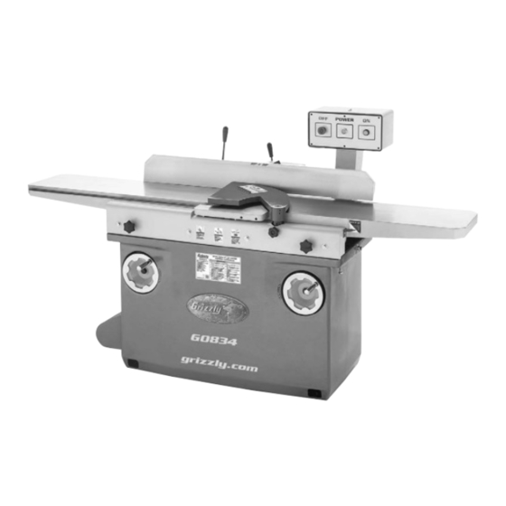
MODEL G0834
12" X 84" JOINTER
w/PARALLELOGRAM BEDS
OWNER'S MANUAL
(For models manufactured since 12/17)
COPYRIGHT © FEBRUARY, 2018 BY GRIZZLY INDUSTRIAL, INC.
WARNING: NO PORTION OF THIS MANUAL MAY BE REPRODUCED IN ANY SHAPE
OR FORM WITHOUT THE WRITTEN APPROVAL OF GRIZZLY INDUSTRIAL, INC.
#ESABJH19004 PRINTED IN CHINA
V1.02.18
Advertisement
Table of Contents

Related Manuals for Grizzly G0834


Summary of Contents for Grizzly G0834
- Page 1 (For models manufactured since 12/17) COPYRIGHT © FEBRUARY, 2018 BY GRIZZLY INDUSTRIAL, INC. WARNING: NO PORTION OF THIS MANUAL MAY BE REPRODUCED IN ANY SHAPE OR FORM WITHOUT THE WRITTEN APPROVAL OF GRIZZLY INDUSTRIAL, INC. #ESABJH19004 PRINTED IN CHINA V1.02.18...
- Page 2 This manual provides critical safety instructions on the proper setup, operation, maintenance, and service of this machine/tool. Save this document, refer to it often, and use it to instruct other operators. Failure to read, understand and follow the instructions in this manual may result in fire or serious personal injury—including amputation, electrocution, or death.
-
Page 3: Table Of Contents
Table of Contents INTRODUCTION ..........2 SECTION 5: ACCESSORIES ......29 Contact Info............ 2 SECTION 6: MAINTENANCE ......30 Manual Accuracy ........... 2 Schedule ............30 Identification ........... 3 Cleaning & Protecting ........30 Controls & Components ......... 4 Lubrication ........... 31 Machine Data Sheet ........ -
Page 4: Introduction
ID label (see below). This information is required for us to provide proper tech support, and it helps us determine if updated documenta- tion is available for your machine. Manufacture Date Serial Number Model G0834 (Mfd. Since 12/17) -
Page 5: Identification
". d) Always use hold-down or push blocks when jointing material narrower than 3" or planing material thinner than 3". e) Never perform jointing, planing, or rabbeting cuts on pieces shorter than 14" in length. Model G0834 (Mfd. Since 12/17) -
Page 6: Controls & Components
C. ON Button: Starts motor when pressed (only table lock and positive stop bolts are if OFF button is not in depressed position). loosened). Infeed Table Adjustment Handwheel: Adjusts position of infeed table (when infeed table lock is loosened). Model G0834 (Mfd. Since 12/17) - Page 7 Note: Even when fence is resting against range of outfeed table movement. A jam nut stops, fence tilt lock must be tightened before locks the positive stop bolt in position so it will starting machine. not move during operation. Model G0834 (Mfd. Since 12/17)
-
Page 8: Machine Data Sheet
Machine Data Sheet MACHINE DATA SHEET Customer Service #: (570) 546-9663 · To Order Call: (800) 523-4777 · Fax #: (800) 438-5901 MODEL G0834 12" X 84" JOINTER WITH SPIRAL CUTTERHEAD Product Dimensions: Weight................................1080 lbs. Width (side-to-side) x Depth (front-to-back) x Height................84 x 39 x 47 in. - Page 9 The information contained herein is deemed accurate as of 1/14/2020 and represents our most recent product specifications. Model G0834 PAGE 2 OF 3 Due to our ongoing improvement efforts, this information may not accurately describe items previously purchased. Model G0834 (Mfd. Since 12/17)
-
Page 10: Section 1: Safety
Never operate under the influence of drugs or injury or blindness from flying particles. Everyday alcohol, when tired, or when distracted. eyeglasses are NOT approved safety glasses. Model G0834 (Mfd. Since 12/17) - Page 11 Make sure they are properly installed, you experience difficulties performing the intend- undamaged, and working correctly BEFORE ed operation, stop using the machine! Contact our operating machine. Technical Support at (570) 546-9663. Model G0834 (Mfd. Since 12/17)
-
Page 12: Additional Safety For Jointers
Straight knives should never project more than ⁄ " (0.125") from cutterhead body. MAXIMUM CUTTING DEPTH. To reduce risk of kickback, never cut deeper than ⁄ " per pass. -10- Model G0834 (Mfd. Since 12/17) -
Page 13: Section 2: Power Supply
To reduce the risk of these hazards, avoid over- loading the machine during operation and make sure it is connected to a power supply circuit that meets the specified circuit requirements. -11- Model G0834 (Mfd. Since 12/17) - Page 14 -12- Model G0834 (Mfd. Since 12/17)
-
Page 15: Section 3: Setup
Grizzly or the shipping agent. You MUST have the original pack- aging to file a freight claim. It is also extremely helpful if you need to return your machine later. -
Page 16: Inventory
• Carbide Inserts 15 x 15 x 2.5mm .... 5 fully check around/inside the machine and packaging materials. Often, these items get lost in packaging materials while unpack- ing or they are pre-installed at the factory. Figure 8. Jointer assembly. -14- Model G0834 (Mfd. Since 12/17) -
Page 17: Cleanup
Figure 11. T23692 Orange Power Degreaser. off the rest with the rag. Repeat Steps 2–3 as necessary until clean, then coat all unpainted surfaces with a quality metal protectant to prevent rust. -15- Model G0834 (Mfd. Since 12/17) -
Page 18: Site Considerations
Only install in an Shadows, glare, or strobe effects that may distract access restricted location. or impede the operator must be eliminated. Wall 30" Minimum Working Clearance 84" 39" Figure 12. Minimum working clearances. -16- Model G0834 (Mfd. Since 12/17) -
Page 19: Moving & Placing Jointer
(refer Note: In next step, use shims between base to Step 1 in Assembly on Page 18 for and floor to avoid warping or cracking cast- instructions). iron base. -17- Model G0834 (Mfd. Since 12/17) -
Page 20: Assembly
Figure 14. Infeed table stop bolt set to stop infeed table at ⁄ " maximum depth of cut. NOTICE NEVER force table handwheels if you feel resistance. Check positions of stop bolts or for obstructions. Figure 15. Securing control panel pedestal. -18- Model G0834 (Mfd. Since 12/17) - Page 21 Tension on Page 44 for instructions). Position and tighten fence tilt handle, as shown in Figure 18. Perform Setting Outfeed Table Height on Page 37. Fence Tilt Handle Figure 18. Positioning and tightening fence tilt handle. -19- Model G0834 (Mfd. Since 12/17)
-
Page 22: Dust Collection
Clear all setup tools away from machine. Dust Hose Hose Clamp Figure 20. Dust hose attached to dust port. Tug hose to make sure it does not come off. Note: A tight fit is necessary for proper performance. -20- Model G0834 (Mfd. Since 12/17) -
Page 23: Recommended Adjustments
(with button pushed in), immediately disconnect power to machine. The OFF button safety feature is not working correctly. This safety feature must work properly before proceeding with regular operations. Call Tech Support for help. -21- Model G0834 (Mfd. Since 12/17) -
Page 24: Section 4: Operations
Read books/magazines or get formal training before beginning any proj- ects. Regardless of the content in this sec- tion, Grizzly Industrial will not be held liable for accidents caused by lack of training. -22- Model G0834 (Mfd. Since 12/17) -
Page 25: Stock Inspection & Requirements
NOT designed to cut metal, glass, stone, Figure 24. Minimum stock dimensions for jointer. tile, products with lead-based paint, or prod- ucts that contain asbestos—cutting these 14" Min. materials with a jointer may lead to injury. -23- Model G0834 (Mfd. Since 12/17) " Min. -
Page 26: Squaring Stock
Rip Cut on a Table Saw—Jointed edge Surface Plane on Jointer—Concave face of of workpiece is placed against a table saw workpiece is surface planed flat with jointer. fence and opposite edge cut off. Previously Jointed Edge -24- Model G0834 (Mfd. Since 12/17) -
Page 27: Surface Planing
Figure 25. Example photo of a surface planing Repeat Step 6 until entire surface is flat. operation. Tip: When squaring up stock, cut opposite side of workpiece with a planer instead of the jointer to ensure boths sides are parallel. -25- Model G0834 (Mfd. Since 12/17) -
Page 28: Edge Jointing
Repeat Step 6 until the entire edge is flat. Tip: When squaring up stock, cut opposite edge of workpiece with a table saw instead of the jointer—otherwise, both edges of work- piece will not be parallel with each other. -26- Model G0834 (Mfd. Since 12/17) -
Page 29: Bevel Cutting
45°. your hands safe, DO NOT let them get closer than 4" from moving cutterhead at any time during operation! Repeat cutting process, as necessary, until you are satisfied with the results. -27- Model G0834 (Mfd. Since 12/17) -
Page 30: Rabbet Cutting
Repeat Step 7 until rabbet is cut to depth. Figure 28. Example photo of typical rabbet cut- ting operation. Re-install cutterhead guard if removed in Step 3. -28- Model G0834 (Mfd. Since 12/17) -
Page 31: Section 5: Accessories
® W1008—Plastic Blast Gate 5" carbide inserts. We've hand picked a selection of commonly used dust collection components for the Model G0834. H2993—4-Pc Machinist Square Set 2", 3", 4" & 6" finely ground stainless steel squares. W1008 W1318 D4218 Figure 32. -
Page 32: Section 6: Maintenance
SECTION 6: MAINTENANCE Schedule Cleaning & Protecting Cleaning the Model G0834 is relatively easy. To reduce risk of shock or Vacuum excess wood chips and sawdust, and accidental startup, always wipe off the remaining dust with a dry cloth. If any... -
Page 33: Lubrication
Protects against rust and corrosion. Ensures stick-free, smooth motion which maximizes finishes and extends the life of your machine. Won’t gum up! 12 oz. AMGA#2 (ISO 68 Equivalent) Figure 34. SB1365 Way Oil. -31- Model G0834 (Mfd. Since 12/17) -
Page 34: Section 7: Service
4. Re-align/replace shaft, pulley, set screw, and key (Page 36). Relocate/shim machine. 6. Dull inserts. 6. Rotate/replace inserts (Page 34). 7. Machine incorrectly resting on floor. 7. Relocate/shim machine. 8. Cutterhead bearings at fault. 8. Replace bearings/re-align cutterhead. -32- Model G0834 (Mfd. Since 12/17) - Page 35 1. Fence not square to table(s); fence tilt not square; tapered unlocked. cut produced. 2. Warped infeed or outfeed table. 2. Regrind/replace table. 3. Inserts not consistently tightened/torqued. 3. Tighten/torque all inserts consistently when securing (Page 34). -33- Model G0834 (Mfd. Since 12/17)
-
Page 36: Rotating/Replacing Cutterhead Inserts
IMPORTANT: If too much oil is applied to the make inserts accessible for removal. threads, excess will attempt to squeeze out of threaded hole as you install insert and force it to raise slightly, making it out of alignment. -34- Model G0834 (Mfd. Since 12/17) -
Page 37: Tensioning/Replacing V-Belts
Remove rear access panel and open cutterhead pulley cover (see Figure 39). Pulley Cover Hex Nuts (2 of 4) Figure 41. Location of motor tension rods and Access hex nuts. Panel Figure 39. Location of rear access panel. -35- Model G0834 (Mfd. Since 12/17) -
Page 38: Checking/Adjusting Pulley Alignment
Tensioning V-Belts on Page 35 for — If pulleys are aligned, no adjustment is instructions). necessary. Replace rear access motor cover and close — If pulleys are not aligned, proceed to cutterhead pulley cover. Step 4. -36- Model G0834 (Mfd. Since 12/17) -
Page 39: Setting Outfeed Table Height
Tensioning V-Belts on Page 35 for instructions). Jam Nut 10. Replace rear access motor cover and close Positive Stop Bolt cutterhead pulley cover. Figure 44. Location of outfeed table lock, positive stop bolt, and jam nut. -37- Model G0834 (Mfd. Since 12/17) -
Page 40: Calibrating Depth-Of-Cut Scale
Re-install cutterhead guard and fence Figure 48. Adjusting scale pointer to " 0 ". assembly, and close cutterhead pulley cover. -38- Model G0834 (Mfd. Since 12/17) -
Page 41: Checking/Adjusting Table Parallelism
Figure 49. Location of outfeed table lock, positions, then outfeed table is not parallel positive stop bolt, and jam nut. with cutterhead. Perform Adjusting Table Parallelism on Page 40. -39- Model G0834 (Mfd. Since 12/17) - Page 42 — If straightedge does not sit flat against infeed and outfeed tables in any of the Adjusting Table positions, perform Parallelism on this page. -40- Model G0834 (Mfd. Since 12/17)
- Page 43 Figure 57. Straightedge Rear Eccentric Outfeed Table Bushings Figure 57. Adjusting outfeed table even with cutterhead body. Figure 55. Locations of front and rear eccentric bushings. -41- Model G0834 (Mfd. Since 12/17)
- Page 44 Figure 59. 15. Perform Setting Outfeed Table Height on Page 37. Straightedge Outfeed Table Infeed Table Figure 59. Infeed and outfeed tables set evenly. -42- Model G0834 (Mfd. Since 12/17)
-
Page 45: Setting Fence Stops
Place sliding bevel set to 45° inward against fence and table, as shown in Figure 62. Verify angle with 90° square, as shown in Figure 63, then retighten jam nut. Sliding Bevel Figure 62. Adjusting fence to 45° inward. -43- Model G0834 (Mfd. Since 12/17) -
Page 46: Adjusting Cutterhead Guard Tension
Re-test and, if necessary, repeat Step 3 until cutterhead guard has correct tension. -44- Model G0834 (Mfd. Since 12/17) -
Page 47: Section 8: Wiring
Technical Support at (570) 546-9663. The photos and diagrams included in this section are best viewed in color. You can view these pages in color at www.grizzly.com. -45- Model G0834 (Mfd. Since 12/17) -
Page 48: Electrical Components
Electrical Components Figure 66. Control panel. Figure 67. Magnetic Switch (behind control panel). Figure 68. Motor junction box. Figure 69. Capacitors. READ ELECTRICAL SAFETY -46- Model G0834 (Mfd. Since 12/17) ON PAGE 45! -
Page 49: Wiring Diagram
NHD NLB22-R AC 220 - 240V People AD11-25/40 220V Electrical Pedestal (viewed from behind) Magnetic Switch Ground Ground Ground Ground Motor 220 VAC L6-30 PLUG Motor Junction Box READ ELECTRICAL SAFETY -47- Model G0834 (Mfd. Since 12/17) ON PAGE 45! -
Page 50: Section 9: Parts
P0834117 BRACKET (RIGHT) P0834136 FENCE KEY P0834118 HEX BOLT M8-1.25 X 35 P0834137 CAP SCREW M5-.8 X 14 P0834119 HEX NUT M8-1.25 BUY PARTS ONLINE AT GRIZZLY.COM! -48- Model G0834 (Mfd. Since 12/17) Scan QR code to visit our Parts Store. -
Page 51: Table
Table BUY PARTS ONLINE AT GRIZZLY.COM! -49- Model G0834 (Mfd. Since 12/17) Scan QR code to visit our Parts Store. - Page 52 P0834244 SHAFT COLLAR P0834287 HEX BOLT M10-1.5 X 50 P0834245 SET SCREW M6-1 X 12 P0834288 SET SCREW M6-1 X 10 BUY PARTS ONLINE AT GRIZZLY.COM! -50- Model G0834 (Mfd. Since 12/17) Scan QR code to visit our Parts Store.
-
Page 53: Cutterhead
TAP SCREW M4 X 10 P0834316 REAR BEARING SUPPORT P0834333 KNOB BOLT M5-.8 X 60 P0834317 CAP SCREW M6-1 X 25 P0834334 LOCK NUT M5-.8 BUY PARTS ONLINE AT GRIZZLY.COM! -51- Model G0834 (Mfd. Since 12/17) Scan QR code to visit our Parts Store. -
Page 54: Stand & Tools
Stand & Tools 435-1 435-2 435-4 435-3 423-1 423-2 423-3 423-4 423-7 423-8 423-6 423-9 423-10 423-11 413 412 BUY PARTS ONLINE AT GRIZZLY.COM! -52- Model G0834 (Mfd. Since 12/17) Scan QR code to visit our Parts Store. - Page 55 CONTROL PANEL CORD 14G 5W 24" P0834434 STRAIN RELIEF TYPE-3 M20-1.5 P0834475 MOTOR CORD 12G 3W 48" P0834435 MAGNETIC SWITCH P0834476 HEX WRENCH 8MM BUY PARTS ONLINE AT GRIZZLY.COM! -53- Model G0834 (Mfd. Since 12/17) Scan QR code to visit our Parts Store.
-
Page 56: Labels & Cosmetics
MUST maintain the original location and readability of the labels on the machine. If any label is removed or becomes unreadable, REPLACE that label before using the machine again. Contact Grizzly at (800) 523-4777 or www.grizzly.com to order new labels. BUY PARTS ONLINE AT GRIZZLY.COM! -54- Model G0834 (Mfd. - Page 57 Would you recommend Grizzly Industrial to a friend? _____ Yes _____No Would you allow us to use your name as a reference for Grizzly customers in your area? Note: We never use names more than 3 times. _____ Yes _____No 10.
- Page 58 FOLD ALONG DOTTED LINE Place Stamp Here GRIZZLY INDUSTRIAL, INC. P.O. BOX 2069 BELLINGHAM, WA 98227-2069 FOLD ALONG DOTTED LINE Send a Grizzly Catalog to a friend: Name_______________________________ Street_______________________________ City______________State______Zip______ TAPE ALONG EDGES--PLEASE DO NOT STAPLE...
-
Page 59: Warranty & Returns
WARRANTY & RETURNS Grizzly Industrial, Inc. warrants every product it sells for a period of 1 year to the original purchaser from the date of purchase. This warranty does not apply to defects due directly or indirectly to misuse, abuse, negligence, accidents, repairs or alterations or lack of maintenance.
Need help?
Do you have a question about the G0834 and is the answer not in the manual?
Questions and answers