
Related Manuals for Grizzly G0875


Summary of Contents for Grizzly G0875
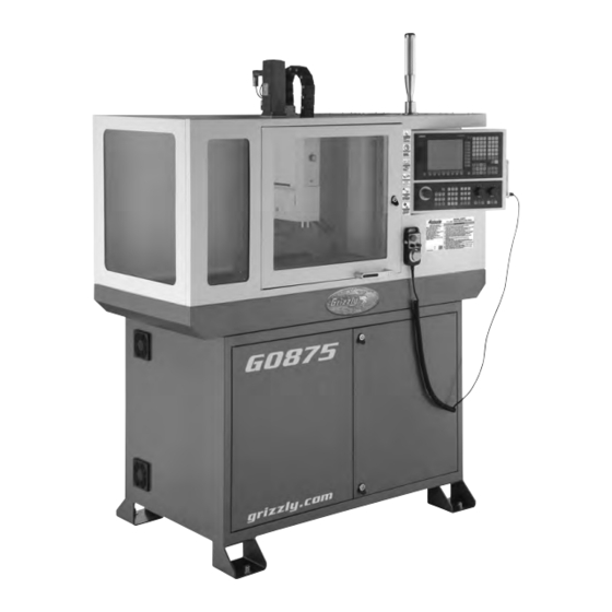
- Page 1 MODEL G0875 7" X 24" ENCLOSED CNC MILL OWNER'S MANUAL (For models manufactured since 3/19)
- Page 2 This manual provides critical safety instructions on the proper setup, operation, maintenance, and service of this machine/tool. Save this document, refer to it often, and use it to instruct other operators. Failure to read, understand and follow the instructions in this manual may result in fire or serious personal injury—including amputation, electrocution, or death.
-
Page 3: Table Of Contents
Table of Contents 6 Operation Machine data sheet ........3 1 Safety Safety ............53 Control and indicating elements ....53 Safety instructions for machinery ....5 Operational modes ........54 Additional safety for CNC mills/lathes .... 7 Programming ..........54 Safety instructions (warning notes) .... - Page 4 Table of Contents (Cont.) 11 Wiring Diagrams 11.1 Wiring safety instructions ......249 11.2 System wiring diagrams (1-2) ..... 250 11.3 System wiring diagrams (3-4) ..... 251 11.4 X/Y/Z motors wiring diagram ...... 252 11.5 Handwheel wiring diagram ......252 12 Parts 12.1 Housing............
-
Page 5: Machine Data Sheet
Customer Service #: (570) 546-9663 · To Order Call: (800) 523-4777 · Fax #: (800) 438-5901 MODEL G0875 7" X 24" ENCLOSED CNC MILL Product Dimensions: Weight ..................................1190 lbs. Width (side-to-side) x Depth (front-to-back) x Height ..................65 x 42 x 78 in. - Page 6 Coolant Capacity ............................... 5 Gallons Construction Spindle Housing/Quill ..............................Steel Table ................................... Cast Iron Head ................................... Cast Iron Column/Base ..............................Cast Iron Base ................................... Cast Iron Stand .................................. Cast Iron Paint Type/Finish ..............................Enamel Model G0875 (Mfd. Since 3/19) Page 2 of 3 Model G0875...
-
Page 7: Safety
Never operate under the influence of drugs or injury or blindness from flying particles. Everyday alcohol, when tired, or when distracted. eyeglasses are NOT approved safety glasses. Model G0875 (Mfd. Since 3/19) - Page 8 Make sure they are properly installed, you experience difficulties performing the intend- undamaged, and working correctly BEFORE ed operation, stop using the machine! Contact our operating machine. Technical Support at (570) 546-9663. Model G0875 (Mfd. Since 3/19)
-
Page 9: Additional Safety For Cnc Mills/Lathes
OFF to avoid ture. Exposure to water creates a shock hazard a possible sudden startup once power is restored. and will reduce life of machine. Model G0875 (Mfd. Since 3/19) -
Page 10: Safety Instructions (Warning Notes)
1.3.2 Other pictograms Activation forbidden! Do not step into the Do not extinguish with Access forbidden! machine! water! Wear safety shoes! Use ear protection! Wear protective glasses! Read the operating instruc- tion before commissioning! Model G0875 (Mfd. Since 3/19) -
Page 11: Intended Use
If the CNC machine is used in any way other than described above, modified without the Intended use approval of Grizzly Industrial, Inc., then the CNC machine is being used improperly. We will not be held liable for any damages resulting from any operation which is not in accord- ance with the intended use. -
Page 12: Reasonably Foreseeable Misuse
If the CNC machine is used and maintained by personnel who are not duly qualified, there may be a risk resulting from incorrect or unsuitable maintenance of the CNC machine. INFORMATION Everyone involved in the assembly, commissioning, operation and maintenance must be duly qualified, -10- Model G0875 (Mfd. Since 3/19) -
Page 13: Qualification Of Personnel
Qualified electricians have been specially trained for the working environment, in which they are working and know the relevant standards and regulations. -11- Model G0875 (Mfd. Since 3/19) - Page 14 We recommend the use of the CNC software SinuTrain as an aid for training and operation. SinuTrain made by Siemens is the perfect software supplement for the CNC machine made by Grizzly Industrial, Inc. This training software supports the efficient training for the operation of the SINUMERIK 808D control unit.
-
Page 15: User Positions
The power supply is cut off when the master switch is in the off position. Except for the areas marked by the pictogram in the margin. In these areas there might be volt- age, even if the main switch is switched-off. Img.1-1: Main switch -13- Model G0875 (Mfd. Since 3/19) - Page 16 Polycarbonate viewing window in chip protection, must be visual inspected by the customer responsible personnel at regular intervals to guarantee the operational safety of the CNC machine. Polycarbonate viewing panes are subject to an aging process and are classified as wear parts. -14- Model G0875 (Mfd. Since 3/19)
-
Page 17: Safety Check
Switch cabinet cooling The cabinet cooling must be running. Separating protective If the protective equipment is open it must not be possible to equipment around the start program. CNC machine Date: Checked by (signature): -15- Model G0875 (Mfd. Since 3/19) -
Page 18: Safety During Operation
Never extinguish using water. If burning magnesium is extinguished with water, this might lead to dangerous reactions (hydrogen gas). Water would be decomposed in its components hydrogen (H) and oxygen (O). Only the following extinguishing agents are permissible: -16- Model G0875 (Mfd. Since 3/19) -
Page 19: Safety During Maintenance
Employers Liability Insurance Association or other supervisory authorities responsible for your company. Check that the lifting and load-suspension equipment are of sufficient load-bearing capability and are in perfect condition. Fasten the loads carefully. Never walk under suspended loads! -17- Model G0875 (Mfd. Since 3/19) -
Page 20: Unattended Operation
1.15 Accident report Inform your supervisors and Grizzly Industrial, Inc. immediately in the event of accidents, possible sources of danger and any actions which almost led to an accident (near misses). -
Page 21: Inspection Deadlines
Please follow the requirements of the Water Resources Law when operating, decommissioning or disassembling the CNC machine or parts hereof. Detailed information regarding this can be found in the Ordinance on Installations for the Handling of Substances Hazardous to Water (VAwS). -19- Model G0875 (Mfd. Since 3/19) -
Page 22: Power Supply
To reduce the risk of these hazards, avoid over- loading the machine during operation and make sure it is connected to a power supply circuit that meets the specified circuit requirements. -20- Model G0875 (Mfd. Since 3/19) -
Page 23: Connection Type
Conduit Conduit Extension Cords Ground Ground Since this machine must be permanently con- Typical setup of a permanently connected nected to the power supply, an extension cord machine. cannot be used. -21- Model G0875 (Mfd. Since 3/19) -
Page 24: Assembly And Commissioning
[kN/m2]“ on page 3) Disassemble the lateral parts of the wooden box. The CNC-machine is lifted and transported with an appropriate handling device to the installation place by means of a fork-lift truck. -22- Model G0875 (Mfd. Since 3/19) - Page 25 "Total weight [kg]“ on page 3. Img.3-2: Example: Transport 2 Bring the CNC-machine with an appropriate handling device, e.g. Electric pallet truck or fork-lift truck at their firm position. -23- Model G0875 (Mfd. Since 3/19)
-
Page 26: Setup And Assembly
The substructure must be prepared in such a way as to ensure that, if any lubricant is used, it cannot penetrate the floor. Protruding parts - such as the dog, handles, etc. - must be secured, where necessary, by means of on-site measures so that persons are not endangered. -24- Model G0875 (Mfd. Since 3/19) - Page 27 "Aligning the machine“ on page 26 INFORMATION The main switch of the CNC machine must be freely accessible. -25- Model G0875 (Mfd. Since 3/19)
- Page 28 -26- Model G0875 (Mfd. Since 3/19)
- Page 29 CNC machine and the substructure (natural frequency of the components). Critical speeds and moves in the axis with displeasing vibrations are rapidly achieved in case of insufficient rigidity of the whole system and will lead to bad milling results. -27- Model G0875 (Mfd. Since 3/19)
-
Page 30: Corrosion Protection
Observe the notes on the connection for machines with frequency converters. Refill coolant The CNC machine is delivered without coolant. Fill the coolant lubricant tank with an appropriate cooling lubricant via the filler hole. "Cooling lubricants“ on page 242 -28- Model G0875 (Mfd. Since 3/19) - Page 31 -29- Model G0875 (Mfd. Since 3/19)
-
Page 32: Refill Central Lubrication System
-30- Model G0875 (Mfd. Since 3/19) - Page 33 Central lubrication system Reducing the discharge volume per cycle: To reduce oil delivery, remove lock screw, measure “A”, turn adjusting screw clockwise, increasing “A”by “B” dimension, as shown on table. 3/16 Lock screw Adjusting screw -31- Model G0875 (Mfd. Since 3/19)
-
Page 34: Warming Up The Machine
2. In the setup menu, select "Reload saved user data". 3. Press <INPUT>. INFORMATION Data that have been backed up can be called again by selecting "System" > "Start-up" > "Power-up with saved data"! -32- Model G0875 (Mfd. Since 3/19) -
Page 35: User Interface, Machine Control Panel
Operating window with program block display Alarm and message prompt area Display Tip and softkey area Information line Current time and date Horizontal softkey bar Program file name Vertical softkey bar Program status indication Active program control modes -33- Model G0875 (Mfd. Since 3/19) -
Page 36: Operating Elements On The Ppu
Alphabetic and numeric keys You use these keys to enter characters or NC commands. Holding down <SHIFT> while pressing an alphabetic or numeric key allows you to enter the upper character shown on the key. -34- Model G0875 (Mfd. Since 3/19) - Page 37 Toggles between the input field and the selected program name. Input key • Confirms your entry of a value. • Opens a directory or program. Alarm cancel key Cancels alarms and messages that are marked with this symbol -35- Model G0875 (Mfd. Since 3/19)
- Page 38 Scrolls upwards on a menu screen Page down key Scrolls downwards on a menu screen Selection key • Toggles in selection lists and selection fields between several options. • Enters the "Set-up menu" dialog at NC start-up. -36- Model G0875 (Mfd. Since 3/19)
- Page 39 Status LEDs LED "RDY" Lights up green: The CNC is ready for operation. LED "TEMP" Unlit: The CNC temperature is within the specified range. Lights up orange: The CNC temperature is out of range. -37- Model G0875 (Mfd. Since 3/19)
- Page 40 Selects text in program blocks. <CTRL> + <C> Copies the selected text. <CTRL> + <D> Shows pre-defined slides on the screen. <CTRL> + <P> Captures screens <CTRL> + <R> Restarts the HMI <CTRL> + <S> Saves start-up archives -38- Model G0875 (Mfd. Since 3/19)
-
Page 41: Elements On The Mcp
All drives will be stopped with the greatest possible braking torque. Handwheel key (with an LED status indicator) Controls the axis movement with external handwheels. -39- Model G0875 (Mfd. Since 3/19) - Page 42 Conditional stop key Stops the program at every block in which miscellaneous function M01 is programmed. Rapid override key Adjusts axis feedrate override Single block key Activates single block execution mode -40- Model G0875 (Mfd. Since 3/19)
- Page 43 Pressing this key approaches the magazine to the reference point. LED on: The magazine is reference point approached. LED off: The magazine is not yet referenced. INFORMATION The G0875 does not have a tool changer. Therefore, the key has no function. Counterclockwise magazine rotation (active only in JOG mode) Pressing this key rotates the magazine counterclockwise.
- Page 44 LED on: The chip conveyor starts forward rotation. LED off: The chip conveyor stops rotation. INFORMATION The G0875 does not have a chip conveyor. Therefore, the key has no function. Reverse rotation of the chip conveyor (active only in JOG mode) Keeping pressing this key in any operating mode rotates the chip conveyor in reverse order.
- Page 45 Traverses the selected axis at rapid traverse speed while pressing the relevant axis key. Inactive key. No function is assigned to this key. Incremental feed keys (with LED status indicators) Sets increments desired for the axis to traverse. Spindle control keys -43- Model G0875 (Mfd. Since 3/19) Page 42...
-
Page 46: Protection Levels
The control system delivered from SIEMENS is set by default to the lowest protection level 7 (without password). -44- User interface, machine control panel Model G0875 (Mfd. Since 3/19) Version 1.0 dated 2017-7-4 Translation of the original instructions Page 43... - Page 47 Tool offsets Work offsets Setting data RS232 settings Program creation / program correction User interface, machine control panel -45- Model G0875 (Mfd. Since 3/19) Page 44 Translation of the original instructions Version 1.0 dated 2017-7-4...
- Page 48 password Change customer’s or manufacturer’s password. Change password Delete Delete customer’s or manufacturer’s password. password -46- User interface, machine control panel Model G0875 (Mfd. Since 3/19) Version 1.0 dated 2017-7-4 Translation of the original instructions Page 45...
- Page 49 Since a direct current may be caused by the frequency converter in the protective earthing con- ductor, if an upstream residual current device (ELCB / RCD) is required in the network, the fol- lowing guidelines must be followed: -47- Model G0875 (Mfd. Since 3/19) macines name Page 46 Translation of the original instructions...
-
Page 50: General Information About Cnc
-48- General information about CNC Model G0875 (Mfd. Since 3/19) Page 48 Translation of the original instructions Version 1.0 dated 2017-07-04... - Page 51 General information about CNC Page 48 Translation of the original instructions Version 1.0 dated 2017-07-04 -49- Model G0875 (Mfd. Since 3/19)
- Page 52 The workpiece coordinate system is determined by the programmer. It can be changed. The location of the origin point for this workpiece coordinate system, also called workpiece origin point is generally user-defined. -50- General information about CNC Model G0875 (Mfd. Since 3/19) Version 1.0 dated 2017-07-04 Translation of the original instructions Page 49...
-
Page 53: Nc Mathematics
The side opposite the angle a is named opposite leg. The side adjacent to the angle a is named adjacent leg. General information about CNC -51- Model G0875 (Mfd. Since 3/19) Page 50 Translation of the original instructions Version 1.0 dated 2017-07-04... -
Page 54: Trigonometric Functions
It applies: tan alpha = opposite leg / adjacent leg The results is: opposite leg = adjacent leg x tan alpha -52- General information about CNC Model G0875 (Mfd. Since 3/19) Version 1.0 dated 2017-07-04 Translation of the original instructions Page 51... -
Page 55: Safety
-53- Model G0875 (Mfd. Since 3/19) -
Page 56: Operation
Due to this systematic program structure, the user is able to create a complete program in a short period of time without having any knowledge of the individual program com- mands and their syntax. Operation -54- Model G0875 (Mfd. Since 3/19) Version 1.0 dated 2017-7-4 Translation of the original instructions Page 53... -
Page 57: Operation Of The Machine
After turning on the G0875, the machine must first be referenced. Without existing reference points (machine zero points), you cannot start and run programs in the control. With the beginning of the reference point approach, the axes should be located in as central a position as possible. - Page 58 Use the Increment button to specify the increment, or press the <JOG> button again to stop the increment again. -56- Model G0875 (Mfd. Since 3/19) Operation Version 1.0 dated 2017-7-4 Translation of the original instructions...
- Page 59 For the following working steps, please proceed as described in "Operation and programming“ of the Siemens "SINUMERIK 808D" Oper- ation instructions. -57- Model G0875 (Mfd. Since 3/19) Operation Page 56 Translation of the original instructions Version 1.0 dated 2017-7-4...
- Page 60 WARNING! A manual movement of axes with open door is not possible. The G0875 has no acknowledgment button to allow movement of axes with open slide door. The lock switch on the slide door may only be unlocked for maintenance and repair work.
- Page 61 Clamp the workpiece in the machine vice. Workpiece Make sure that the workpiece is firmly clamped in the vise. Machine vice Img.6-3: Clamping the workpiece -59- Model G0875 (Mfd. Since 3/19) Operation Page 58 Translation of the original instructions Version 1.0 dated 2017-7-4...
-
Page 62: Inserting Tool
Construction data are transmitted (semi-) automatically to an executable program by means of the CAD/CAM program (for instance a 3D-CAD program including downstream co-processor). -60- Operation Model G0875 (Mfd. Since 3/19) Version 1.0 dated 2017-7-4 Translation of the original instructions Page 59... -
Page 63: Starting The Program
In case of a failure or a fault in the central lubricating system, a stick-slip effect may occur. This effect describes the jerky sliding of solid bodies moving opposite one another. For instance: creaking doors and rattling windscreen wipers. -61- Model G0875 (Mfd. Since 3/19) Operation Page 60 Translation of the original instructions... -
Page 64: Data Interfaces And Current Collection
100 - 200 30 - 100 300 - 400 This results in the following standard speeds, dependent on mill diameter, mill type and material. -62- Operation Model G0875 (Mfd. Since 3/19) Version 1.0 dated 2017-7-4 Translation of the original instructions Page 61... - Page 65 The workpieces need to be tensed in flexibly and stably (vice, screw clamp). Operation -63- Model G0875 (Mfd. Since 3/19) Page 62 Translation of the original instructions Version 1.0 dated 2017-7-4...
- Page 66 Follow the manufacturer’s disposal instructions. INFORMATION The CNC milling machine is lacquered with a one-component paint. Take this criterion into account when selecting your cooling lubricant. -64- Operation Model G0875 (Mfd. Since 3/19) Version 1.0 dated 2017-7-4 Translation of the original instructions Page 63...
- Page 67 MCP mode MCP mode coordinate coordinate Changing system Changing system Passwords Passwords The 808D machine co Moving Moving axis (MCP) is used to selec axis machine operating mo JOG - MDA - AUTO keys -65- Model G0875 (Mfd. Since 3/19)
- Page 68 Menu navigation Operating area navigation MCP mode Changing The 808D machine control panel Mode navigation (MCP) is used to select the machine operating mode : JOG - MDA - AUTO -66- Model G0875 (Mfd. Since 3/19)
- Page 69 The 808D machine control panel (MCP) is used to control OEM machine functions. The machine functions can be activated 808D (PPU) has eight ho with the appropriate keys. be activated with the cor -67- Model G0875 (Mfd. Since 3/19)
- Page 70 Act. val. Work(WCS) Meas. Meas. Face T,S,M Sett. work. tool cutt. 808D (PPU) has eight horizontal SKs on the bottom of the screen. These SKs can be activated with the corresponding button (located below). -68- Model G0875 (Mfd. Since 3/19)
- Page 71 Step 1 the respective axis. The service mode is ope appropriate key combina In the service mode, th can be activated and de Step 2 password Change password Delete password -69- Model G0875 (Mfd. Since 3/19)
- Page 72 In the service mode, the password Change can be activated and deactivated. password Delete password Step 2 Enter customer’s or manufacturer’s password password Change Change customer’s or manufacturer’s password password Delete customer’s or manufacturer’s password Delete password -70- Model G0875 (Mfd. Since 3/19)
- Page 73 Switch on Switch on the machine Function of machine keyboard Step 1 MCP mode Reference Changing Turn on the main switch machine Step 2 Make sure you perform t Release on the m -71- Model G0875 (Mfd. Since 3/19)
- Page 74 Please note the explicit switching on rules as specified by the machine manufacturer. Step 1 Turn on the main switch of the machine. Step 2 Make sure you perform the following operation! Release all the emergency stop buttons on the machine! -72- Model G0875 (Mfd. Since 3/19)
- Page 75 (circle) is displayed between the axis identifier and the value. Step 2 The axes are referenced with the corresponding axis traversing keys. The traversing direction and keys are specified by the machine manufacturer. -73- Model G0875 (Mfd. Since 3/19)
- Page 76 After returning to JOG mode, use the axis traversing keys to move the machine manually. The machine can now be operated in JOG mode. During normal operation (JOG),the referenced symbol is not shown on the screen. -74- Model G0875 (Mfd. Since 3/19)
- Page 77 Press “Offset” o Start Create spindle tool Press the “Tool list” SK o Create tool Measure edge tool Machine Load tool into coordinate active spindle system position User Move Execute M machine with interface function handwheel -75- Model G0875 (Mfd. Since 3/19)
- Page 78 A tool must have been created and measured tool before executing the program. Step 1 Please make sure the system is in JOG mode. Press “Offset” on the PPU. Tool Press the “Tool list” SK on the PPU. list -76- Model G0875 (Mfd. Since 3/19)
- Page 79 Press the “OK” SK on the PPU. Enter the ”Radius” of the milling tool. Tool Tool list wear Press the “Edges Press the “New edge Press the “Input” button on the PPU. -77- Model G0875 (Mfd. Since 3/19)
- Page 80 Radius edge Reset edge Delete edge Back Work User Tool Tool offset data list wear var. data Press the “Edges” SK on the PPU. Edges Press the “New edge” SK on the PPU. edge -78- Model G0875 (Mfd. Since 3/19)
- Page 81 A maximum of nine tool edges can be created for each tool! Different tool lengths and radii can be saved in different tool edges as required. Please select the right tool edge for machining according to requirement! -79- Model G0875 (Mfd. Since 3/19)
- Page 82 Other M function Back Press ´CYCLE START´ to activate above functions. Meas. Meas. Face Sett. tool work. cutt. Press “CYCLE START” on the MCP dges as Press the “Back” SK on the PPU back -80- Model G0875 (Mfd. Since 3/19)
- Page 83 “Handwheel” function w appropriate keys. on the MCP Under “WCS” or “MCS” state, a handwheel will be shown beside the axis symbols, showing the axis is chosen, and can be controlled with a handwheel. -81- Model G0875 (Mfd. Since 3/19)
- Page 84 MCP for selecting the axis of handwheel, the user will have to activate “Handwheel” function with PPU softkey. Handwheel beside osen, Handwheel Select the required axis on Number Axis the right of the PPU; the selected axis is shown with a √ -82- Model G0875 (Mfd. Since 3/19)
- Page 85 Activate zerooffset Other M function Back Press the “Mea Press ´CYCLE START´ to activate above functions. Meas. Meas. Face Sett. tool work. cutt. Press the “Measure m Press the “CYCLE START” key on the MCP -83- Model G0875 (Mfd. Since 3/19)
- Page 86 Press the “Machine” key on the PPU Press the “JOG” key on the MCP Meas- Press the “Meas. tool” SK on the PPU tool Measure Press the “Measure manual” SK on the PPU manual -84- Model G0875 (Mfd. Since 3/19)
- Page 87 Z0 or The measured tool length the workpiece. length value column of the Step 2 Measure diam Press the Move directly to zero point Use a setting block. -85- Model G0875 (Mfd. Since 3/19)
- Page 88 The measured tool length is now shown in “Length (L)”. This value is also saved in the length value column of the corresponding tool list at the same time. Step 2 Measure diameter Press the “Diameter” SK on the PPU Diameter -86- Model G0875 (Mfd. Since 3/19)
- Page 89 Meas. work. Press the ”Se Press the “Handwheel” key on the MCP and position the tool at the location X0 or of the workpiece. Press Move directly to zero point Use a setting block. -87- Model G0875 (Mfd. Since 3/19)
- Page 90 X0/Y0 according to requirement.) Workpiece edge Tool measurement manual diameter Diameter Back Meas. Meas. Face Sett. cutt. work. tool Press the ”Set diameter” SK on the PPU diameter Press the “Back” SK on the PPU back -88- Model G0875 (Mfd. Since 3/19)
- Page 91 Other M function Press ´CYCLE START´ Meas Press “Spindle right” on the MCP to start the work spindle in the clockwise direction. Press “CY The coolant functio Press the “Reset” k Press t -89- Model G0875 (Mfd. Since 3/19)
- Page 92 Press “CYCLE START” on the MCP. The coolant function button on MCP is active. Press the “Reset” key on the MCP to stop the coolant function. Press the “Back” SK on the PPU. -90- Model G0875 (Mfd. Since 3/19)
- Page 93 Press th Press th Create workpiece offset Ente Test tool Select “M3” using th offset results T,S,M T,S,M Tool change Spindle speed Spindle direction Activate zerooffset Other M function Press ´CYCLE START´ Press the “CYCLE -91- Model G0875 (Mfd. Since 3/19)
- Page 94 Tool change Spindle speed Spindle direction Activate zerooffset Other M function Back Press ´CYCLE START´ to activate above functions. Meas. Meas. Face Sett. tool work. cutt. Press the “CYCLE START” key on the MCP -92- Model G0875 (Mfd. Since 3/19)
- Page 95 Press th Press “Reset” on the MCP to stop the spindle rotation Press the “Mea Press the “Back” SK on the PPU As the following red fram tools to simplify the opera Meas. T,S,M work. -93- Model G0875 (Mfd. Since 3/19)
- Page 96 Press the “Meas. work.” SK on the PPU. Meas. work. As the following red frame shows, 808D provides the user with three methods of using tools to simplify the operating process. Back Meas. Meas. Face T,S,M Sett. cutt. work. tool -94- Model G0875 (Mfd. Since 3/19)
- Page 97 Press the axis traverse keys to move the tool to the required setting position in the X axis. Press the “Set W “Step 2” must be repeate If you change the tool be must remeasure the leng -95- Model G0875 (Mfd. Since 3/19)
- Page 98 “Step 2” must be repeated for the setting of Y and Z zero points. If you change the tool because of wear/damage during the machining process, you must remeasure the length of the tool. -96- Model G0875 (Mfd. Since 3/19)
- Page 99 Save P4 Work offset rectangular workpiece. Offset Offset Compensation data have been act Meas. T,S,M work. Compensation data have been activated! Back Meas. Face Meas. Sett. T,S,M work. tool cutt. -97- Model G0875 (Mfd. Since 3/19)
- Page 100 Workpiece measurement, center of circle o point of the workpiece as the as the Work offset center point of the circular workpiece. orkpiece. Offset Compensation data have been activated! Back Meas. Meas. Face T,S,M Sett. tool cutt. work. -98- Model G0875 (Mfd. Since 3/19)
- Page 101 Make sure the feedrate override on the MCP is at 0%! Press “CYCLE START” on the MCP. Increase the feedrate override gradually to avoid accidents caused by an axis moving too fast. Observe whether the axis moves to the set position. -99- Model G0875 (Mfd. Since 3/19)
- Page 102 Return to change to User User Imperial and Behaviors at Setting a delay T, F, S function interface Metric system interface corners in the program Geometry data / mot Return to change to End/stop motion -100- Model G0875 (Mfd. Since 3/19)
- Page 103 N75 S3000 M3 G94 F100 N80 G00 X50 Y50 Z5 Geometry data / motion N85 G01 Z-5 N90 Z5 Return to change tool N95 G00 Z500 D0 N100 G00 G40 G53 X0 Y0 Z500 D0 End/stop motion -101- Model G0875 (Mfd. Since 3/19)
- Page 104 Step 3 Create a new program with the “New” SK on the right of the PPU. Name Type Length Date Time Execute The system will save it au -102- Model G0875 (Mfd. Since 3/19)
- Page 105 Cancel key to open file, [DEL] key to delete file Step 5 Now the program is opened and can be edited. The system will save it automatically after editing. -103- Model G0875 (Mfd. Since 3/19)
- Page 106 With G70 at the header, Execute the geometry data will be in the imperial (inches) Renumber unit system, the feedrate in the default metric Search system. Mark Copy Paste Mill. Edit Cont. Drill. Sin. Activate comp. -104- Model G0875 (Mfd. Since 3/19)
- Page 107 (inches) N15 S5000 M3 G94 F300 unit system, the feedrate in the default metric N20 G00 X3.93 Y3.93 Geometry data / motion system. N25 G01 Z-0.787 Z0.196 Return to change tool N35 G00 Z19.68 -105- Model G0875 (Mfd. Since 3/19)
- Page 108 N10 T1 D1 M6 value in G500 will be N15 S5000 M3 G94 F300 added to the value in G500 Y G54. N20 G00 G54 X20 Y20 Z5 N25 G01 Z-20 N35 G00 G53 Z500 -106- Model G0875 (Mfd. Since 3/19)
- Page 109 N20 G00 X3.93 Y3.93 Z0.196 Finally you should change the N25 G01 G91 Z-0.787 4 F300 program to absolute positioning with Z0.196 G90. N35 G00 Z19.68 4 F300 Y20 Z5 -107- Model G0875 (Mfd. Since 3/19)
- Page 110 When G01 is activated in N30 Z5 machines with automatic gram, the axis will travers N35 G00 Z500 D0 tool changer. programmed feed rate in line, according to the fee defined by G94 or G95. -108- Model G0875 (Mfd. Since 3/19)
- Page 111 When G01 is activated in the pro- gram, the axis will traverse at the programmed feed rate in a straight Straight line (parallel/ line, according to the feed rate type unparallel to axis) defined by G94 or G95. -109- Model G0875 (Mfd. Since 3/19)
- Page 112 Arrow indicates the direction of tool motion along the contour. -110- Model G0875 (Mfd. Since 3/19)
- Page 113 The result of the two commands will be such that the cutter goes very fast around a corner motion or slow on the contour. -111- Model G0875 (Mfd. Since 3/19)
- Page 114 Two common types of defining circles and arcs: G3 = define circle :G02/G03 X_Y_I_J_; ① :G02/G03 X_Y_CR=_; ② Arcs ≤180º,CR is a positive number Arcs >180º,CR is negative number When milling circles, you can only use to define the program! ① -112- Model G0875 (Mfd. Since 3/19)
- Page 115 J = defined relative increment from start point to center point in Y G2 = define circle direction in traversing direction = G2 clockwise G3 = define circle direction in traversing direction = G3 counter-clockwise -113- Model G0875 (Mfd. Since 3/19)
- Page 116 N30 Z5 G74 Z=0 ;reference point can be used to paus tools’ movements during G75 X=0 ;fixed point operation F5: Program pause This makes the surface o workpiece much smoothe -114- Model G0875 (Mfd. Since 3/19)
- Page 117 N25 G01 Z-5 N30 G04 F5 F5: Program pause of 5 s N35 Z5 M4 This makes the surface of the N40 M5 workpiece much smoother N45 M19 N35 G00 Z500 D0 -115- Model G0875 (Mfd. Since 3/19)
- Page 118 (specified side length of Contour milling Hole triangle with chamfer as with cycle centering CHF=Chamfer (specified base line lengt isosceles triangle with ch Milling slots Drilling base line) and spigots holes Tapping actual effect -116- Model G0875 (Mfd. Since 3/19)
- Page 119 N95 G01 F300 Z-10 actual effect N100 G41 Y 90 N102 G01 X 5 N105 G01 X12 RND=5 N110 G01 Y97 CHR=2 N115 G01 X70 RND=4 N120 G01 Y90 N125 G01 G40 X80 N130 G00 Z50 -117- Model G0875 (Mfd. Since 3/19)
- Page 120 “Center drilling” ,and parameterize the cycle according to requirements. Modal call N325 MCALL CYCLE82 Cancel N330 X20 Y20 ; Hole wi N335 X40 Y40 ; Hole wi N340 MCALL N345 X60 Y60 ; Hole wi -118- Model G0875 (Mfd. Since 3/19)
- Page 121 N325 MCALL CYCLE82( 50.000, -3.000, 2.000, -5.000, 0.000, 0.200) Cancel N330 X20 Y20 ; Hole will be centered N335 X40 Y40 ; Hole will be centered N340 MCALL N345 X60 Y60 ; Hole will not be centered -119- Model G0875 (Mfd. Since 3/19)
- Page 122 N325 MCALL CYCLE83 90.00000, 0.70000, 0.50 Modal N330 X20 Y20 ; Hole wi call N335 X40 Y40 ; Hole wi Cancel N340 MCALL N345 X60 Y60 ; Hole wi -120- Model G0875 (Mfd. Since 3/19)
- Page 123 90.00000, 0.70000, 0.50000, 1.00000, 0, 0, 5.00000, 1.40000, 0.60000, 1.60000) Modal N330 X20 Y20 ; Hole will be drilled call N335 X40 Y40 ; Hole will be drilled Cancel N340 MCALL N345 X60 Y60 ; Hole will not be drilled -121- Model G0875 (Mfd. Since 3/19)
- Page 124 DTD <0:unit is r, DTD DAM=2 depth for 0.6 s =0:same as DTB DIS1=1.6 When reinserting a quill, you can For specific explanations program a distance limit of 1.6 mm please refer to the standard handbook -122- Model G0875 (Mfd. Since 3/19)
- Page 125 Remaining depth =10 < ce plane =6-2=4 2xFDPR, the remaining depth ecides distribute by the last two drilling (FDPR-3DAM)-DAM vates only =4-2=2 DAM=2 n value is DAM=2 n value is DAM=2 DAM=2 DAM=2 ations standard -123- Model G0875 (Mfd. Since 3/19)
- Page 126 SKs on the right. Rigid Thread → tapping Retract plane, absolute Select “Thread” using the vertical SKs ,and then select “Rigid tapping”, and parameterize the cycle according to requirement. Modal call Cancel -124- Model G0875 (Mfd. Since 3/19)
- Page 127 With the “Modal call” SK, holes will be tapped at subsequently programmed positions until cancelled with the MCALL command in the part program. Examples are shown on the next page . Modal call Cancel -125- Model G0875 (Mfd. Since 3/19)
- Page 128 N330 X20 Y20 ; Hole will be tapped SST1=5 Retrac N335 X40 Y40 ; Hole will be tapped N340 MCALL N345 X60 Y60 ; Hole will not be tapped SST a synchr feed ra actual effect -126- Model G0875 (Mfd. Since 3/19)
- Page 129 SST and SST1 control the spindle speed and the Z axis feed position synchronously. During execution of CYCLE 84, the switches of the feed rate override and the cycle stop (feed hold) are deactivated. -127- Model G0875 (Mfd. Since 3/19)
- Page 130 → pattern circle STA1=90 Angle Select “Hole pattern” INDA=60 Angle using the vertical SKs NUM=6 Drill 6 ,and then select “Hole circle”, and parameterize The cy the cycle according to the ho requirement. Cancel -128- Model G0875 (Mfd. Since 3/19)
- Page 131 Angle between the circle and horizontal coordinate is 90º INDA=60 Angle between the circles is 60º NUM=6 Drill 6 holes on circle The cycle is used together with the drilling fixed cycle to decrease the hole clearance. Cancel -129- Model G0875 (Mfd. Since 3/19)
- Page 132 Name of contour subroutine The “Contour milling” SK can be found in the file vertical SKs on the right. Attach contour Contour milling The parameterization is performed as in this figure. Cancel Edit Cont. -130- Model G0875 (Mfd. Since 3/19)
- Page 133 Make sure that the cursor has moved to the contour writing file position (as shown in the Attach contour figure). Search Mark Copy Paste Cancel Tech Cont. Edit interface -131- Model G0875 (Mfd. Since 3/19)
- Page 134 Press “Technical interface” on the PPU to return to the interface for setting the cycle data. After finishing the parameter settings of CYCLE72, press the ”OK” SK on the PPU to insert the corresponding cycles in the main program. -132- Model G0875 (Mfd. Since 3/19)
- Page 135 After all the settings take effect, the selected cycle and set data will be transferred to corresponding part program automatically (for further information, see next page). -133- Model G0875 (Mfd. Since 3/19)
- Page 136 N245 CYCLE72( "SUB_PART_1", 50.00000, 0.00000, 2.00000, -5.00000, 5.00000, 0.00000, 0.00000, 300.00000, 100.00000, 111, 41, 12, 3.00000, 300.00000, 12, 3.00000) cont RL=41(absolute value) cont AS1=12 circl LP1=3 20 m FF3=300 path AS2=12 Retu in sp LP2=3 -134- Model G0875 (Mfd. Since 3/19)
- Page 137 Return along the 1/4 circle on the path Parameter explanations in space are the same as for AS1 LP2=3 The radius of the return circle is 20 The length of the returning path is along the line to approach -135- Model G0875 (Mfd. Since 3/19)
- Page 138 “Mill.” SK. actual effect The relevant cycle can be found using the vertical SKs on the right. Circumf. Slots → slots Select “slot” using the vertical SKs and parameterize the cycle according to requirement. -136- Model G0875 (Mfd. Since 3/19)
- Page 139 With the “OK” SK, the values and cycle call will be transferred to the part program as shown below. This will perform milling at the position defined in the cycle. actual effect -137- Model G0875 (Mfd. Since 3/19)
- Page 140 Page 119 FFCP= Feed rate For descriptions of CPA, CPO and RAD, please see Page 129 path, unit i For descriptions of FFD and FFP1, please see Page 135 Before rec -138- Model G0875 (Mfd. Since 3/19)
- Page 141 If FFP2/SSF are not specified, then use the feed rate/spindle speed of rotation as default FFCP= Feed rate at the center position on the circle path, unit is mm/min Before recalling the cycle, you must set the tool radius compensation value. -139- Model G0875 (Mfd. Since 3/19)
- Page 142 -140- Model G0875 (Mfd. Since 3/19)
- Page 143 (Axis Description do not move) This unit describes how to simulate a part program before executing it in AUTO mode. Content Step 1 The part program must b Simulate program (Axis do not move) -141- Model G0875 (Mfd. Since 3/19)
- Page 144 A part program must have been created before program (Axis it can be tested using “Simulation”. do not move) O mode. Step 1 The part program must be opened using the “Program Manager” on PPU. -142- Model G0875 (Mfd. Since 3/19)
- Page 145 If this message is displayed at the bottom of the screen, press the “AUTO” mode key on the MCP. Press the “Edit” SK on th -143- Model G0875 (Mfd. Since 3/19)
- Page 146 If the control is not in the correct mode, a message ot in the will be displayed at the message bottom of the screen. at the een. Press the “Edit” SK on the PPU to return to the program. -144- Model G0875 (Mfd. Since 3/19)
- Page 147 This unit describes how to simulate a part program before executing it in AUTO mode. Execution Content Program Execution Press the “Ex Dry Run The control is now i current opened prog displayed and the AUT Now the prog operation will -145- Model G0875 (Mfd. Since 3/19)
- Page 148 The control is now in AUTO mode with the current opened program storage path being displayed and the AUTO lamp on the MCP is Now the program is ready to start and the actual operation will be described in the next section! -146- Model G0875 (Mfd. Since 3/19)
- Page 149 (If you don’t u the door Enter the required feedrate in mm/min, enter “2000 ” in the example. Press “CYCLE STAR Turn the feedrat After finishing to the origina Press the “Input” key of the PPU. machining! -147- Model G0875 (Mfd. Since 3/19)
- Page 150 Turn the feedrate override gradually to the required value. After finishing the dry run, please turn the changed offset back to the original value in order to avoid affecting the actual machining! -148- Model G0875 (Mfd. Since 3/19)
- Page 151 This unit describes how to use the Time counter function and how to machine pieces and Counter the compensation setting for the tool wear. Content Step 1 Press the “M Time Press th Counter Press the “Time Piece- Machining User Tool Wear interface -149- Model G0875 (Mfd. Since 3/19)
- Page 152 Make sure the machine has been referenced before pieces and Counter machining workpieces! Step 1 Press the “Machine” key on the PPU. Press the “Auto” key on the MCP. Press the “Time counter” SK on the PPU. -150- Model G0875 (Mfd. Since 3/19)
- Page 153 (or select the M01 functi Notes:M01 function → there is M01 code. Make sure th Press “Door” on the MC you don’t use this funct Press “CYCLE START -151- Model G0875 (Mfd. Since 3/19)
- Page 154 Press “Door” on the MCP to close the door of the machine. (If you don’t use this function, just close the door on the machine manually.) Press “CYCLE START” on the MCP to execute the program. -152- Model G0875 (Mfd. Since 3/19)
- Page 155 Press the “Auto” key on the MCP. wear compensation. Positive value: tool is aw Negative value: tool is cl Use the direction keys to select the required tools and their edges. Press “Input” on the PP -153- Model G0875 (Mfd. Since 3/19)
- Page 156 Positive value: tool is away from workpiece (set radius bigger than real one) Negative value: tool is close to workpiece (set radius smaller than real one) Press “Input” on the PPU to activate the compensation. -154- Model G0875 (Mfd. Since 3/19)
- Page 157 Press th Press the “Bloc Block Search Press the “Interr. poin cursor will move to th Note: The cursor can be m program block with the tr Press the “To e (can also pres -155- Model G0875 (Mfd. Since 3/19)
- Page 158 “To end point”: The program will continue from the line with the breakpoint. Press the “To end point” SK on the PPU. (can also press “To contour” if required) -156- Model G0875 (Mfd. Since 3/19)
- Page 159 Make sure the correct tool is selected before continuing! Press the “CYCLE START” key on the MCP to execute the program. Alarm 010208 is shown at the top prompting to press the “CYCLE START” key to continue the program. -157- Model G0875 (Mfd. Since 3/19)
- Page 160 Press the “CYCLE START” key on the MCP to execute the program. Turn the feedrate override on the MCP gradually to the required value. y to -158- Model G0875 (Mfd. Since 3/19)
- Page 161 Press “Progr parameters Press the Time Shared Network change Drive (only ADVANCED) Press the Save Help data Adjust the parameters in communication SW on P Manual face Gear cutting change Press t Press t -159- Model G0875 (Mfd. Since 3/19)
- Page 162 Press the “Settings” SK on the PPU. Adjust the parameters in “Communication settings” to match the settings of communication SW on PC. Press the “Save” SK on the PPU. Press the “Back” SK on the PPU. -160- Model G0875 (Mfd. Since 3/19)
- Page 163 The PPU will display a window showing the progress of the transfer. Check the interface settin from PC. (Press ”Send Data” on SI The PPU will display a w If there is a problem during transfer of the part program, a window will be displayed. -161- Model G0875 (Mfd. Since 3/19)
- Page 164 Check the interface setting and start the communication software to send the program from PC. (Press ”Send Data” on SINUCOM PCIN to send data.) The PPU will display a window showing the progress of the transfer. played. -162- Model G0875 (Mfd. Since 3/19)
- Page 165 Use “Cursor + Select” to select the required part program. The selected program will be highlighted. Press the “Copy” SK on the PPU. Press "Network Press the “NC” SK on the PPU. Press the “Paste” SK on the PPU. -163- Model G0875 (Mfd. Since 3/19)
- Page 166 Connect PC using a network cable to the rear X130 ethernet port on the PPU Press key: Press key: Press “Serv. Displ.” SK Press “Serv. Displ.” SK m NC to e on the Press "Network Info" button to enter the "Local Configuration Data" -164- Model G0875 (Mfd. Since 3/19)
- Page 167 When the "data storage end" is Select "OK" to complete displayed, the input data activation effect. Note: The address "10.10 on the first step in the IP PPU and PC IP address same network segment. -165- Model G0875 (Mfd. Since 3/19)
- Page 168 Select "OK" to complete the setup. Note: The address "10.10.10.2" setting is based on the first step in the IP address of the PPU. PPU and PC IP address should be kept in the same network segment. -166- Model G0875 (Mfd. Since 3/19)
- Page 169 In this folder you can put some machining program. Add the network drive on the PPU side to activate the shared folder, and Step 4 online processing In the “Network drive configuration” screen select “Net drv. Config.” -167- Model G0875 (Mfd. Since 3/19)
- Page 170 Press “Add Drive” SK to add it to the specified drive letter After set successful, the screen will displayed “Network drive added successfully” while the set path is automatically written to the “drive” Window. der, and g.” -168- Model G0875 (Mfd. Since 3/19)
- Page 171 Press “netwo. Drive” SK to enter the network drive Press the “Cycle Start” interface. button for machining operation. Press “Enter” Button to open network drive to PC/PG. Note: You can also use t Drive” moving files. -169- Model G0875 (Mfd. Since 3/19)
- Page 172 AUTO mode, select the appropriate NC program. Press the “Cycle Start” button for machining operation. Note: You can also use the “Copy”, “Paste” key to achieve “NC”, “USB” and “Network Drive” moving files. -170- Model G0875 (Mfd. Since 3/19)
- Page 173 Press the “Input” key on The online help manual of the OEM will be shown on the screen. Press the “TOC” SK on the PPU. The online help from the Siemens manual will be shown. -171- Model G0875 (Mfd. Since 3/19)
- Page 174 Press the “JOG” key on the MCP. Press the “Sett.” SK on the PPU. Enter appropriate values in “Retraction plane” and “Safety distance”. Press the “Input” key on the PPU to activate the settings. -172- Model G0875 (Mfd. Since 3/19)
- Page 175 Make sure that the override value on the MCP is 0%! Press the “Cycle Start” key on the MCP. Adjust the override on the MCP gradually to the required values. -173- Model G0875 (Mfd. Since 3/19)
- Page 176 Programming the STOPRE command in a block will stop block preprocessing and buffering. The following block is not executed until all preprocessed and saved blocks have been executed in full. The preceding block is stopped in exact stop (as with G9). -174- Model G0875 (Mfd. Since 3/19)
- Page 177 N40 G00 X-10.0 Y0 Z10 N50 R1=0 R2=0 R3=0 N60 STOPRE N70 M00 N80 R1=1 N90 STOPRE N100 M00 N110 R2=2 N120 STOPRE N130 M00 N140 R3=R1+R2 N150 STOPRE N160 G00 X=R3 N170 M30 blocks ith G9). -175- Model G0875 (Mfd. Since 3/19)
- Page 178 “Sa Save Press the “Date time” SK on the PPU. data Press “Shift” and “Alarm Make sure the password Press th Enter a new “Date” and “Time”. Press the “OK” SK on the PPU. -176- Model G0875 (Mfd. Since 3/19)
- Page 179 Make sure the password is set to the “CUSTOMER” access level. Press the “Save data” SK on the PPU. Press the “OK” SK on the PPU. While the control is saving data to the system, do not operate or switch off the control! -177- Model G0875 (Mfd. Since 3/19)
- Page 180 Gear stage 3 → M43 If the operator is manually selecting the gear stage in the part program, it is the operator’s responsibility to select the correct gear stage according to the required speed. -178- Model G0875 (Mfd. Since 3/19)
- Page 181 Make sure th User Coordinate Program rotation skip function interface ROT AROT Press “CYCLE STAR Machine Machine Subprogram Turn the feedrate overrid coordinate coordinate Scaling Calculator system system User Polar Program coordinates interface example -179- Model G0875 (Mfd. Since 3/19)
- Page 182 Make sure the feedrate override on the MCP is at 0%! Press “CYCLE START” on the MCP to execute the MDA program. Turn the feedrate override on the MCP gradually to the required value. -180- Model G0875 (Mfd. Since 3/19)
- Page 183 However, the following ru End program and back to Select gear stage the beginning automatically The name can contain let End subprogram M41~M45 Change spindle gear characters long. M3 / M4 / M5 Spindle CW/CCW/Stop Example: LRAHMEN7 -181- Model G0875 (Mfd. Since 3/19)
- Page 184 When you create the program, the program name may be freely selected. However, the following rule should be observed: The name can contain letters, numbers and underscores and should be between 2 and 8 gear characters long. Example: LRAHMEN7 -182- Model G0875 (Mfd. Since 3/19)
- Page 185 Subprograms can be called from a main program, and also from another subprogram. In total, up to eight program levels, including the main program, are available for this type of nested call. -183- Model G0875 (Mfd. Since 3/19)
- Page 186 Starting from the plus direction of X axis and rotates CCW. It is saved and must only be written in blocks in which it changes, after the pole or the plane has been changed. program. In this type of -184- Model G0875 (Mfd. Since 3/19)
- Page 187 ; polar coordinate N100 ... AP=26.3 RP=7.344 Z4 ; polar coordinate and Z axis(= cylinder coordinate) Programming example N20 TRANS X20.0 Y15. Point defined by RP, AP RP=... AP=... Pole Example G17: X/Y plane TRANS -185- Model G0875 (Mfd. Since 3/19)
- Page 188 ATRANS X...Y... Z... ; programmable offset, additive to existing offset (incremental) TRANS ; without values, clears old commands for offset ordinate) Programming example N20 TRANS X20.0 Y15.0 programmable offset subprogram call TRANS Y TRANS X... -186- Model G0875 (Mfd. Since 3/19)
- Page 189 ; without values, clears old commands for offset If a program contains SC N10 G17 N20 AROT RPL=45 additive 45 degree rotation subprogram call Programming example N10 G17 N20 SCALE X2.0 Y2.0 ATRNS X -187- Model G0875 (Mfd. Since 3/19)
- Page 190 If a program contains SCALE or ASCALE, this must be programmed in a separate block. Programming example N10 G17 N20 SCALE X2.0 Y2.0 ; contour is enlarged two times in X and Y subprogram call Workpiece ATRNS X..Y..SCALE X2 Y2 Original Workpiece -188- Model G0875 (Mfd. Since 3/19)
- Page 191 ② enlarge 1.3 times in X and Y ATRANS Y-60 N125 AROT RPL=-10 direction N130 ASCALE X1.3 Y1.3 N135 REPEAT LAB1 LAB2 P N140 In this example, the positive direction of the XY coordinate axis is different when machining each groove! -189- Model G0875 (Mfd. Since 3/19)
- Page 192 Y axis coordinate moves 60 in negative direction AROT RPL=-10 N125 N130 ASCALE X1.3 Y1.3 N130 N135 groove enlarged 1.3 times in the X,Y direction. REPEAT LAB1 LAB2 P1 N135 N140 machining the same groove at the new position N140 -190- Model G0875 (Mfd. Since 3/19)
- Page 193 GOTOF+ label: Jump forward (in the direction of the end block of the program) GOTOB+ label:Jump backward (in the direction of the start block of the program) Label: Name of the selected string (standing for the required jump program block) or block number -191- Model G0875 (Mfd. Since 3/19)
- Page 194 This equires a N70 LABEL0: R1=R2+R3 N80 GOTOF LABEL1; jumps to label LABEL1 N90 LABLE2: M30; program ends ock) or N110 LABEL1: N130 GOTOB LABEL2 ;jumps to label LABEL2 Unconditional jump example -192- Model G0875 (Mfd. Since 3/19)
- Page 195 Using “;” code to add a string will be skipped without remark to the N85 function, execution. without any influence on the execution. When ”SKP” is displayed After activating “SKP”, us purple circle), the string w -193- Model G0875 (Mfd. Since 3/19)
- Page 196 When ”SKP” is displayed (red circle), the skip function has been activated. After activating “SKP”, using “/” at the beginning of the program string (shown in purple circle), the string will be skipped without influencing the execution. -194- Model G0875 (Mfd. Since 3/19)
- Page 197 If the input fie value into the Use the “Acce Press the “=“ SK on the PPU. cursor positio automatically -195- Model G0875 (Mfd. Since 3/19)
- Page 198 If the input field is already occupied by a value, the calculator will take this value into the input line. Use the “Accept” SK to enter the result in the input field at the current cursor position of the part program editor. The calculator will then close automatically. -196- Model G0875 (Mfd. Since 3/19)
- Page 199 This unit shows three typical program examples of frequently used milling cycles and the program 1 corresponding machining diagrams with detailed explanations. Content Milling program 1 Milling program 2 Machine Milling coordinate program 3 system Tool information: T1 Milling tool D50 T2 Milling tool D8 -197- Model G0875 (Mfd. Since 3/19)
- Page 200 1 have been performed before machining! The zero point of the workpiece is located at the center point of the workpiece Tool information: T1 Milling tool D50 T2 Milling tool D8 -198- Model G0875 (Mfd. Since 3/19)
- Page 201 X axis is 0º), feedrate 300 mm/min, milling direction G2, rough machining, use G1 vertical groove center to insert. ; ==Adaptive rotation around Z axis== N180 rotation in positive direction 90º N190 _END: Milling end sign -199- Model G0875 (Mfd. Since 3/19)
- Page 202 ; ====Finishing rectangular pocket milling ===== N270 repeat N230~N260 operation three times N280 cancel all the coordinate rotation commands g=== ; =====Cancel rotation=========== 5 mm, s 4 mm, angle axis is n G2, center to -200- Model G0875 (Mfd. Since 3/19)
- Page 203 X axis in positive direction is 45º, angle between the holes is 60º, circular hole number 6 →) N400 cancel mode use N410 Tool information: T1 Milling tool D50 T2 Milling tool D12 T4 Milling tool D10 -201- Model G0875 (Mfd. Since 3/19)
- Page 204 LL” mode to decided by ate(X0,Y0), with first hole in positive es is 60º, Tool information: T1 Milling tool D50 T2 Milling tool D12 T4 Milling tool D10 -202- Model G0875 (Mfd. Since 3/19)
- Page 205 G0 X3 Y3 G2 X3.27 Y-40.91 I=AC(-52.703) J=AC(-19.298) G3 X46.27 Y-47 I=AC(38.745) J=AC(54.722) G1 X42 Y-8 X3 Y3 M2;/* end of contour */ d the width arallel to d the width o the X -203- Model G0875 (Mfd. Since 3/19) nishing...
- Page 206 ; ========Path milling end Tool information T1 Milling tool D50 T5 Milling tool D5 T2 Milling tool D12 T6 Drilling tool D10 T3 Milling tool D10 T7 Drilling tool D5 T4 Milling tool D16 T8 Tap D6 -204- Model G0875 (Mfd. Since 3/19)
- Page 207 ; ========Path milling end======== N200 left side radius compensation N210 circle, milling radius is 5 mm N220 incline, milling side length is 2 mm N230 N240 N250 cancel tool radius compensation N260 ; =========Path milling end====== -205- Model G0875 (Mfd. Since 3/19)
- Page 208 300 mm/min, plane machining feedrate 300 mm/min, milling direction G3, slot edge finishing allowance 0.2 mm, complete machining ways, finishing machining feedrate 250 mm/min, spindle speed rate 3000 r/min ; ========Slot milling end======= -206- Model G0875 (Mfd. Since 3/19)
- Page 209 300 mm/min, milling in positive direction, rough ngle 90º, machining, use G1 vertical groove center to insert. plane N570 repeat N600 milling process, the difference direction is the machining allowance. m, complete ; ==Rectangular pocket milling end== drate 250 -207- Model G0875 (Mfd. Since 3/19)
- Page 210 10 mm, start angle 90º, angle between the holes is 60º, circular hole number 6 N770 continue drilling with (X36,Y24.1) as the center point N780 cancel mode recall instruction ; =========Drilling end=========== -208- Model G0875 (Mfd. Since 3/19)
- Page 211 ***CONTOUR**** tion is 1.4 rt lead G17 G90 DIAMOF G0 X7 Y0 G1 Y61.35 0 mm, start G2 X13.499 Y86 I=AC(57) J=AC(61.35) º, circular G1 X63 RND=2 as the M2;/* end of contour */ -209- Model G0875 (Mfd. Since 3/19)
- Page 212 808D ISO mode. Content ISO function switch Method 1 Press the “Shift” + “Sy Input the manufa function switch Press ISO code explanation A dialog box appear the new setting. S ISO program transfer and operation -210- Model G0875 (Mfd. Since 3/19)
- Page 213 Press the “Shift” + “System - Alarm” keys on the PPU. Input the manufacturer’s password (“SUNRISE”) Press the “ISO mode” SK on the right. A dialog box appears prompting whether to activate the new setting. Select the “OK” SK to activate it. -211- Model G0875 (Mfd. Since 3/19)
- Page 214 G291/G290 before R commands must be set separately M3/M4/M5 Spindle r in a line! M98 P _L_ Subprog End of S If ISO is displayed at the top of the screen, it is activated. -212- Model G0875 (Mfd. Since 3/19)
- Page 215 Reverse circle (note the form there must be ”, ” before R parameter) ds must eparately M3/M4/M5 Spindle right / spindle left / spindle stop As DIN M98 P _L_ Subprogram call (P+ subprogram name/ L+ times) Program name End of Subroutine -213- Model G0875 (Mfd. Since 3/19)
- Page 216 G04 X2.0 ;delay 2 s Circles greater than 180° are a Y-550 ;after orientation drilling, back to values start point → ② G02 X6.0 Y2.0 R-50.0 ;cancel the fixed cycle N70 M5 ;spindle rotation stop N80 M30 -214- Model G0875 (Mfd. Since 3/19)
- Page 217 Circles less than 180° is assigned positive values Y=50mm → ① G02 X6.0 Y2.0 R50.0 End point Circles greater than 180° are assigned negative g, back to X6.0 Y 2.0 values → ② G02 X6.0 Y2.0 R-50.0 Start point Y=50mm -215- Model G0875 (Mfd. Since 3/19)
- Page 218 Retraction motion(+Z) → G87 / G89 In 808D, the default ISO program feed distance unit is mm! (X100→100mm) → → Note: change the parameter 10884 = 0, to make X100 100 um / X100. 100 mm -216- Model G0875 (Mfd. Since 3/19)
- Page 219 ;after orientation drill 5th hole, back to R point G98 Y750 ;after orientation drill 6th hole, back to R point G80 ;cancel fixed cycle G28 G91 X0 Y0 Z0 ;back to reference point ;spindle rotation stop -217- Model G0875 (Mfd. Since 3/19)
- Page 220 Y-550 ;after orientation drill 5th hole, back to R point ③ Retraction motion (+Z) → fa G98 Y-750;after orientation drill 6th hole, back to start plane ;cancel fixed cycle G28 G91 X0 Y0 Z0 ;back to reference point ;spindle rotation stop -218- Model G0875 (Mfd. Since 3/19)
- Page 221 Retraction motion (+Z) → fast feed start plane G98 Y-750. ;after orientation drill 6th hole, back to start plane ;cancel fixed cycle G28 G91 X0 Y0 Z0 ;back to reference point ;spindle rotation stop -219- Model G0875 (Mfd. Since 3/19)
- Page 222 Motion at the bottom of the hole → Motion at the bottom of the none pause ③ ③ Retraction motion (+Z) → cutting feed Retraction motion (+Z) → feed Origin R point Z point -220- Model G0875 (Mfd. Since 3/19)
- Page 223 Except that the spindle stops at the bottom of the hole, same as ② Motion at the bottom of the hole → pause ③ Retraction motion (+Z) → cutting feed Origin R point Z point Pause -221- Model G0875 (Mfd. Since 3/19)
- Page 224 Origin Make the ne Step 2 spindle start R point Programs in I changes mus Z point Z point the ISO progr Using G98 Using G99 spindle stop spindle stop -222- Model G0875 (Mfd. Since 3/19)
- Page 225 Step 2 dle start Programs in ISO mode in the 808D have their own rules. Suitable changes must be made at the appropriate positions so that you can run the ISO programs! e stop -223- Model G0875 (Mfd. Since 3/19)
- Page 226 H list in the tool list is open. Note: Every tool only can use the H value corresponding to the edge. In the graphic above, T2 H1 cannot be executed. A specified ISO program -224- Model G0875 (Mfd. Since 3/19)
- Page 227 Press the “USB” SK on the PPU. Press the “Paste” SK on the PPU. A specified ISO program is then stored in the USB and can be executed as required. -225- Model G0875 (Mfd. Since 3/19)
- Page 228 N150 Y-50,R10 N160 X40 N170 X0 N180 G03X-20Y-70R20 N190 G1G40X0 N200 G0Z50 Note: This program open with the G291/G290 com recommended to use the open ISO mode — using active button on the PPU -226- Model G0875 (Mfd. Since 3/19)
- Page 229 Note: This program opens/exits ISO mode N440 G290 with the G291/G290 command. It is N450 M30 recommended to use the first method to open ISO mode — using the ISO mode active button on the PPU (described above) -227- Model G0875 (Mfd. Since 3/19)
- Page 230 N120 M3S2500M8 N130 MCALL CYCLE83( 50, 0, 2, -20, ,-5, ,3, 0.5, 1, 1, 1, 3, 3, 0, ,0) N140 CYCLE802( 111111111, 111111111, 40, - 40, 40, 40, -40, 40, -40, -40, ,) N150 MCALL -228- Model G0875 (Mfd. Since 3/19)
- Page 231 Group 2: Non-modally val Name Meaning Dwell time Tapping wit Reference Fixed point G147 SAR - Appr G148 SAR - Retra G247 SAR - Appr G248 SAR - Retra G347 SAR - Appr G348 SAR - Retra -229- Model G0875 (Mfd. Since 3/19)
- Page 232 SAR - Retract with a straight line G247 SAR - Approach with a quadrant G248 SAR - Retract with a quadrant G347 SAR - Approach with a semicircle G348 SAR - Retract with a semicircle -230- Model G0875 (Mfd. Since 3/19)
- Page 233 Name Meaning Group 12: Exact stop wi G40 * Tool radius compensation OFF Name Meaning Tool radius compensation left of contour G601 * Exact stop Tool radius compensation right of contour G602 Exact stop -231- Model G0875 (Mfd. Since 3/19)
- Page 234 Continuous — path mode Group 11: Exact stop, non-modal Name Meaning Non-modal exact stop Group 12: Exact stop window modally effective Name Meaning G601 * Exact stop window G602 Exact stop window, course, with G60, G9 -232- Model G0875 (Mfd. Since 3/19)
- Page 235 Group 16: Feedrate override modally effective Name Meaning CFC * Feedrate override with circle ON CFTCP Feedrate override OFF Group 18: Behavior at corner when working with tool radius compensation Name Meaning G450 * Transition circle G451 Point intersection -233- Model G0875 (Mfd. Since 3/19)
- Page 236 Approach and retraction in the plane (SAR) Group 47: External NC languages modally effective Name Meaning G290 * Siemens mode G291 External mode Transformations Name Meaning TRACYL Cylinder. Peripheral surface transformation TRANSMIT Transmit: Polar transformation TRAFOOF Deactivate transformation -234- Model G0875 (Mfd. Since 3/19)
-
Page 237: Code List, M Functions
Cooling lubricant pump OFF Return from subroutine Spindle stop in defined limit position Program end with resetting (Reset) Clamp workpiece Loosen workpiece Workpiece change -235- Model G0875 (Mfd. Since 3/19) F150 TC CNC Version 1.0 dated 2017-7-4 Original operating instructions Page 153... - Page 238 Function Function -236- Model G0875 (Mfd. Since 3/19) F150 TC CNC Page 154 Original operating instructions Version 1.0 dated 2017-7-4...
-
Page 239: G Functions To Pal
Circular interpolation anti-clockwise with polar coordinates Linear tangential travelling on a contour Linear tangential travelling off the contour Accurate stop off -237- Model G0875 (Mfd. Since 3/19) F150 TC CNC Version 1.0 dated 2017-7-4 Original operating instructions Page 155... -
Page 240: Notes, Messages And Error Messages
NO POSITION SIGNALS FROM TURRET 700026 Not able to find expected tool in monitor time 700027 APPROACH REF.POINT AGAIN AFTER ROT. MONITORING -238- Model G0875 (Mfd. Since 3/19) 808D Notes, messages and error messages Page 156 Original operating instructions Version 1.0 dated 2017-07-04... - Page 241 NC start not possible 700060 Channel not in reset, change PRT not possible 700061 User alarm 62 700062 User alarm 63 -239- Model G0875 (Mfd. Since 3/19) Notes, messages and error messages 808D Version 1.0 dated 2017-07-04 Original operating instructions Page 157...
- Page 242 User alarm 65 700065 User alarm 66 700066 User alarm 67 700067 User alarm 68 700068 User alarm 69 -240- Model G0875 (Mfd. Since 3/19) 808D Notes, messages and error messages Page 158 Original operating instructions Version 1.0 dated 2017-07-04...
- Page 243 For any questions regarding the CNC control, please contact: Siemens AG, A&D techsupport Phone (+49) 0180 50 50 222 mailto: techsupport@ad.siemens.de Siemens AG Hotline, Helpline Phone (+49) 0180 50 50 111 -241- Model G0875 (Mfd. Since 3/19) Version 1.0 dated 2017-7-4 Translation of the original instructions Page 159...
-
Page 244: Maintenance
Take this criterion into account when selecting your cooling lubricant. The company Grizzly Industrial, Inc. does not assume any guarantee for sub- sequent damages due to unsuitable cooling lubricants. The flashpoint of the emulsion must be higher than 140°C. -
Page 245: Safety
The selection of cooling lubricants and slideway oils, lubricating oils or greases as well as their care are being determined by the machine operator or operating company. Therefore, Grizzly Industrial, Inc. cannot be held liable for machine damages caused by unsuitable coolants and lubricants as well as by inadequate maintenance and servic- ing of the coolant. -
Page 246: 10.3 Inspection And Maintenance
The type and level of wear depends to a large extent on the individual usage and operating conditions. Any indicated intervals therefore are only valid for the corresponding approved con- ditions. Interval Where? What? How? Check "Safety check“ on page 15 Cleaning Clean the milling table and the chip tray. -244- Model G0875 (Mfd. Since 3/19) - Page 247 Check the pH value. If required, replace the Measure pH value cooling lubricant. "Drain the compressed air service unit“ on Draining page 247 Check Check the drive belt on wear and excessive clearance. Readjusting If necessary, replace the timing belt. Replacing -245- Model G0875 (Mfd. Since 3/19)
-
Page 248: Polycarbonate Windows
In the following cases, an immediate replacement is strongly recommended: plastic deformation (distortion) by previous impact stress, cracks, Damage to the edge seal, immersion of lubricating coolant in the composite structure, destroyed or damaged safety screen (coating) on the workspace or operator's side. -246- Model G0875 (Mfd. Since 3/19) -
Page 249: Sliding Door Interlock Switch
Check the water level daily and drain the water level in the filter if necessary. 10.7 Recommended wearing parts Polycarbonate viewing panes Sliding door interlock switch Wipers on the guide tracks Couplings of the axis drives -247- Model G0875 (Mfd. Since 3/19) Maintenance Version 1.0 dated 2017-7-4 Translation of the original instructions Page 165... -
Page 250: Cooling Lubricants And Tanks
Used oils must be delivered to a collection centre. Consult your supervisor if you do not know where the collection centre is. -248- Model G0875 (Mfd. Since 3/19) Coolant lubricating Version 1.0 dated 2017-07-04 Translation of the original instructions... -
Page 251: Wiring Safety Instructions
EXPERIENCING DIFFICULTIES. If you are expe- the requirements at the beginning of this manual riencing difficulties understanding the information when connecting your machine to a power source. included in this section, contact our Technical Support at (570) 546-9663. -249- Model G0875 (Mfd. Since 3/19) -
Page 252: System Wiring Diagrams (1-2)
System Wiring Diagram (1) Main Switch Spindle Servo Drive Power Coolant Lubrication System Wiring Diagram (2) DC24V Power CNC Power On Lamp SP Left SP Right Coolant Pump Tool Loose READ ELECTRICAL SAFETY -250- Model G0875 (Mfd. Since 3/19) ON PAGE 249! -
Page 253: System Wiring Diagrams (3-4)
System Wiring Diagram (3) Tool Door Pressure Active Loose X100 X101 X102 System Wiring Diagram (4) Tool Lamp Cool Brake Green Yellow Loose 808D CNC X200 X201 READ ELECTRICAL SAFETY -251- Model G0875 (Mfd. Since 3/19) ON PAGE 249! -
Page 254: X/Y/Z Motors Wiring Diagram
X/Y/Z Motors Wiring Diagram X Motor X Driver Y Motor Y Driver Z Motor Z Driver Handwheel Wiring Diagram 808D CNC Handwheel READ ELECTRICAL SAFETY -252- Model G0875 (Mfd. Since 3/19) ON PAGE 249! -
Page 255: Parts
PARTS We do our best to stock replacement parts when possible, but we cannot guarantee that all parts shown are available for purchase. Call (800) 523-4777 or visit www.grizzly.com/parts to check for availability. Housing REF PART # DESCRIPTION REF PART #... -
Page 256: Stand
REAR PANEL P0875113 LUBRICANT PUMP P0875106 COOLANT TANK P0875114 TERMINAL BRACKET P0875107 COOLANT TANK COVER P0875115 GASKET P0875108 COOLANT TANK TRAY BUY PARTS ONLINE AT GRIZZLY.COM! -254- Model G0875 (Mfd. Since 3/19) Scan QR code to visit our Parts Store. -
Page 257: Base
P0875209 SIEMENS SERVO MOTOR 1FL6044 P0875221 Y-AXIS COVER BASE PLATE P0875210 FLANGE P0875222 COUPLER P0875211 GUIDE P0875223 OIL SEPARATOR P0875212 SHIELD BUY PARTS ONLINE AT GRIZZLY.COM! -255- Model G0875 (Mfd. Since 3/19) Scan QR code to visit our Parts Store. -
Page 258: Column
LINEAR GUIDE WAY EGH15CA P0875314 BASE PLATE P0875307 COLUMN COVER P0875315 OIL SEPARATOR B P0875308 Z-AXIS SERVO MOTOR BASE P0875316 SLIDING BLOCK EGH15CA BUY PARTS ONLINE AT GRIZZLY.COM! -256- Model G0875 (Mfd. Since 3/19) Scan QR code to visit our Parts Store. -
Page 259: Milling Head
P0875414 MOTOR PULLEY P0875431 SPINDLE PULLEY 36T P0875415 JUNCTION PLATE P0875432 P0875416 WIRE COVER P0875433 SPANNER NUT M30-2.5 P0875417 SENSOR M8 BUY PARTS ONLINE AT GRIZZLY.COM! -257- Model G0875 (Mfd. Since 3/19) Scan QR code to visit our Parts Store. -
Page 260: Milling Table
LOCK NUT M12-1.75 P0875518 WIRE COVER P0875509 SIEMENS SERVO MOTOR 1FL6042 P0875519 MOTOR COVER P0875510 LEADSCREW MOUNT (RIGHT) P0875520 CABLE CARRIER BUY PARTS ONLINE AT GRIZZLY.COM! -258- Model G0875 (Mfd. Since 3/19) Scan QR code to visit our Parts Store. -
Page 261: Pneumatic System
601-2 P0875601-2 MANOMETER P0875605 QUICK EXHAUST VALVE 601-3 P0875601-3 PRESSURE REGULATOR P0875606 CYLINDER TOOL SPANNER 601-4 P0875601-4 LUBRICATOR P0875609 DRIP LUBRICATOR BUY PARTS ONLINE AT GRIZZLY.COM! -259- Model G0875 (Mfd. Since 3/19) Scan QR code to visit our Parts Store. -
Page 262: Labels & Cosmetics
Safety labels help reduce the risk of serious injury caused by machine hazards. If any label comes off or becomes unreadable, the owner of this machine MUST replace it in the original location before resuming operations. For replacements, contact (800) 523-4777 or www.grizzly.com. BUY PARTS ONLINE AT GRIZZLY.COM! -260- Model G0875 (Mfd. -
Page 263: Warranty & Returns
WARRANTY & RETURNS Grizzly Industrial, Inc. warrants every product it sells for a period of 1 year to the original purchaser from the date of purchase. This warranty does not apply to defects due directly or indirectly to misuse, abuse, negligence, accidents, repairs or alterations or lack of maintenance.
Need help?
Do you have a question about the G0875 and is the answer not in the manual?
Questions and answers