Table of Contents
Advertisement
Advertisement
Table of Contents

Related Manuals for Hisense HK560


Summary of Contents for Hisense HK560
- Page 1 User Manual (HK560) QingDao Hisense Intelligent Commercial System Co.,Ltd.
-
Page 2: Table Of Contents
CONTENT CONTENT ....................2 PART 1 SYSTEM INTRODUCTION ............4 SAFETY NOTICES BEFORE INSTALLATION OR USE ........4 SYSTEM INTRODUCTION ..............5 BASIC PRODUCT CONFIGURATION ............ 6 I/O PANEL ....................7 MAIN BOARD INTERFACE DESCRIPTION ........... 7 PART II SYSTEM ASSEMBLY AND DISASSEMBLY ....... 9 1. - Page 3 1. SWITCHING INSTRUCTION ..............28 2. INSTRUCTIONS FOR USING MAGNETIC STRIPE CARDS ....28 3. INSTRUCTIONS FOR USING RFID CONTACTLESS CARDS ....29 PART V ACCESSORIES ANNEXES ............30 APPENDIX A ..................30 APPENDIX B ..................30...
-
Page 4: Part 1 System Introduction
Part 1 System Introduction Safety Notices Before Installation or Use ☆ It is required grounded well and the supply voltage shall be stable, and you must confirm that the voltage of the outlet provides shall be in line with the voltage marked on the label of the unit. ☆... -
Page 5: System Introduction
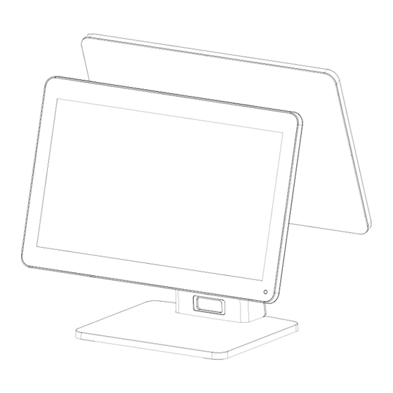
1. System Introduction The appearance of the whole machine has the following modes: Single-screen Device, length * width * height: 405 * 210 * 330; main screen flip range: 0- 45 degrees Dual-screen Device, length * width * height: 405 * 250 * 370; main screen flip range: 0-45 and second screen flip angle 0-30. -
Page 6: Basic Product Configuration
Power on(S1) Blue standby mode(S3) 2. Basic product configuration Category Parts HK560 Intel® Celeron® processor (Baytrail-D) J1900Quad Core, clock speed1.99GHz up to 2.42GHz, TDP 10W System Windows 7 / Windows 10 / Ubuntu linux Memory DDRIIIL 4G (Up to 8G) -
Page 7: I/O Panel
Power Power Adapter1 Adapter(DC 24V,2.5A)standard for device without printer or CubeX Power Adapter2 Adapter ( DC 24V, 5A) for device with printer or CubeX Printer optional 80mm printer 58mm printer External Cash drawer Steel Cash Drawer (Supporting Dual cash drawer) card reader optional Magnetic stripe card reader/RFID contactless card reader... - Page 8 Jumpers / Headers and Connectors SYS_FAN1 System Fan Connector CLR_CMOS1 CMOS Clear Jumper J_VGA1 VGA Pin Header J_COM4, J_COM5, J_COM6 COM4-6 Pin Headers F_USB1 Front USB2.0 Pin Header1 J_PWRCOM4 COM4 VCC Select Jumper F_USB2 Front USB2.0 Pin Header2 F_USB3 Front USB2.0 Pin Header3 F_USB4 Front USB2.0 Pin Header4 F_PANEL1...
-
Page 9: Part Ii System Assembly And Disassembly
R_USB1(R_USB5) POWER USB 24V Key-2 Connector (USB2.0 TYPE-A Connector) R_USB2 USB2.0 Dual TYPE-A Connector R_USB3 USB3.0+USB2.0 TYPE-A Connector COM1 COM1 RJ50 Connector COM2 COM1 RJ50 Connector COM3 COM1 RJ50 Connector RJ45_1 LAN RJ45 Connector Line-out 3.5mm Jack J_PWRCOM4 (COM4 VCC Select Jumper 3*2 Pin 2.54mm) CLR_CMOS1 (CMOS Clear Jumper 3*1 Pin 2.54mm) Part II System Assembly and Disassembly 1. - Page 10 After removing the screw, pull the rear shell of the base forcefully according to the graphic method, remove the rear shell of the base, and then see the transfer plate fixed inside the base. Figure 2 Host 15.6 inch 10.1inch Host VFD cable Host...
-
Page 11: Hard Disk Replacement
1.4 Rotate the main screen and the secondary screen to the vertical angle, remove the three fixing screws of the main screen and the second screen (15.6 inch screen/10.1 inch screen/VFD) respectively, and carefully pass the screen cable through the cable hole. Separate the main and auxiliary screen from the base respectively. -
Page 12: Installation Of Card Reader
Figure 7 3. Installation of Card Reader Description: The hard disk can be replaced directly on the host computer. In order to display pictures more clearly, the base and other components are hidden in the following pictures. Remove the card reader cover Card reader cover... -
Page 13: Fingerprint Reader Installation
Figure 10 4. Fingerprint reader installation 1.10 Remove Fingerprint reader cover Fingerprint reader cover Figure 11 1.11 Insert the reserved cables in the host into the terminal base of the Fingerprint reader Terminal base Figure 12 1.12 The Fingerprint reader is installed in the graphical direction and fixed by locking an M3*8 screw. -
Page 14: Part Iii System Installation
Figure 13 Part III System Installation 1. Inspection of installation environment It is important to choose a safe and reliable place to install the terminal. Choose a table or table large and strong enough to support the weight of the system and peripherals. Choose a flat, hard surface. - Page 15 2. Touch screen setting find MouserRegister software in Touch Panel Double-click to run, set the value to 50, click set, set up. 3. MSR setting Install...
- Page 16 open and select USB Pop up the lower interface and click on the tag location In this interface, you can select the settings that need to be modified, click Update, and then update the modified settings to the card switcher.
- Page 17 4. RFID test Open demo The operation steps are as follows:...
- Page 18 5. Fingerprint reader driver installation and testing Find the device that needs to install driver in the Device Manager. Double-click to Open. The update steps are as follows:...
- Page 19 Find the driver storage location, update completed Find the test demo, double-click to open The fingerprint data can be read out by putting the finger on the fingerprint reader after 1-2-3. 6. 10 inch second screen settings Click on the lower right corner to open the graphics card control software...
-
Page 20: Bios
After you run it, click Display icon as below Monitor Hisense is selected in blank 1, resolution can be adjusted in blank 2, rotation direction of secondary screen can be adjusted in blank 3, and setting can be saved in blank... - Page 21 1. Main This topic introduces the basic information of the basic input/output system (BIOS) on the main page. Parameter Description BIOS BIOS Version: S395A 0.10 x64 Information Build Date and Time:- MM/DD/YEAR hh:mm:ss Product Serial Number: The Product Serial Number of the Mainboard System Date Current system date.
- Page 22 Parameter Description ACPI Settings System ACPI Parameters Super IO Configuration System Super IO Chip Parameters Hardware Monitor Monitor hardware status Power Button Control Power Button Control Settings Power Control COM2-3 Pin9 Settings S5 RTC Wake Settings S5 RTC Wake Settings CPU Configuration CPU Configuration Parameters LCD Control...
- Page 23 Hardware Monitor...
- Page 24 Parameter Description CPU Temp The temperature of CPU SYS Temp The temperature of Environment SYS_FAN1 The speed of SYS_FAN1 VCC_CPU The Voltage of CPU VCC_DDR The Voltage of DDR The Voltage of +12 The Voltage of +5 +3.3 The Voltage of +3.3 Power Button Control...
- Page 25 Parameter Description PowerOn after Select AC Power state to when power is re-applied after a power PowerFail failure Power Off: When the current is restored, the computer is shut down. Power On: When the current is restored, the computer is in the boot state.
- Page 26 Parameter Description COM2 Pin9 Selection Set the definition of the Pin9 of COM2(Signal,5V,12V) COM3 Pin9 Selection Set the definition of the Pin9 of COM3(Signal,5V,12V) OS Configuration Select Windows 7 & Android & Windows 8.x and 10,default Windows 10 for US...
- Page 27 3. Boot This topic introduces the configuration of bootstrap functions. Parameter Description Boot Configuration Setup Prompt Timeout Number of seconds to wait for setup activation key. 65535(0xFFFF) means indefinite waiting. Bootup NumLock State Select the keyboard NumLock state FullScreen Logo Enable or disable Full Screen Logo Fast Boot Enable or disable Fast Boot...
-
Page 28: Part Iv Instructions For Usage
Parameter Description Save Changes and Reset system setup after saving the changes. Reset Discard Changes and Reset system setup without saving any changes. Reset Restore Defaults Restore/Load Default Values for all the setup options. Save as User Defaults Save the changes done so far as User Defaults Restore User Defaults Restore the User Defaults to all the setup options Boot Override... -
Page 29: Instructions For Using Rfid Contactless Cards
When swiping the card, the machine should be placed on a hard horizontal plane. Please scratch the magnetic strip of the magnetic strip card inward from the swipe slot. The card swiping process should be smooth and uniform. 3. -
Page 30: Part V Accessories Annexes
Part V Accessories Annexes Item Note Adaptor Power cable Appendix A BIOS Set Up 1. Copy all files in the file directory of the compressed package to the U-disk root directory. 2. Connect only U-disk, not other storage devices, press F11 to boot, pull out the startup menu, select "UEFI: Built-in EFI Shell"... - Page 31 #define BIT3 0x08 #define BIT4 0x10 #define BIT5 0x20 #define BIT6 0x40 #define BIT7 0x80 #define IO_Base 0xA00 #define CDS_PORT IO_Base+1 #define CDO_PORT IO_Base+2 void Init_DIO_Default() /*----------------------------------------------- @brief : Set CD_OPEN power level @Input : Level-- 0:Low 1: High ------------------------------------------------*/ void Set_CD_OPEN(int Level) { int t;...
- Page 32 /*Set_CD_OPEN High */ Set_CD_OPEN(1); /*Set_CD_OPEN Low */ Set_CD_OPEN(0); while(1) Get_CD_SENSE_Status();...
Need help?
Do you have a question about the HK560 and is the answer not in the manual?
Questions and answers