Advertisement
Table of Contents
- 1 Copyright Statement
- 2 Part 1. System Introduction
- 3 General Specifications
- 4 Front View
- 5 Back View
- 6 Part 2. System Installation
- 7 Checking the Location for Installation
- 8 Part 3. System Utilization
- 9 Touch Panel
- 10 Connectors& Functions
- 11 Power Connector
- 12 Part 4. System Assembly & Disassembly
- 13 Hdd Replacement
- 14 Bios Setup
- 15 Appendix B .Io Information
- Download this manual
Advertisement
Table of Contents

Related Manuals for Hisense HK570


Summary of Contents for Hisense HK570
- Page 1 HK570 Touch Terminal User’s Manual Document Version 1.0...
-
Page 2: Copyright Statement
Copyright Statement © 2016 Hisense Company Ltd. All Rights Reserved. All material in this System Integration Manual is the property of Hisense Company Ltd. and its subsidiaries, and is protected under International, US, CANADA, MEXICO copyright and/or other intellectual property laws. Reproduction or transmission of the materials, in whole or in part, in any manner, electronic, print, or otherwise, without the prior written consent of Hisense Company Ltd. - Page 3 Part 1. System Introduction 01. Safety Notices Before Installation or Use 02. System Introduction 03. General Specifications 04. Front View 05. Back View 06. Dimension 07. I/O View Part 2. System Installation 01. Checking the Location for Installation 02. Before Connecting Peripherals 03.
-
Page 4: Part 1. System Introduction
Part 1. System Introduction 01. Safety Notices Before Installation or Use ☆ It is required grounded well and the supply voltage shall be stable, and you must confirm that the voltage of the outlet provides shall be in line with the voltage marked on the label of the unit. - Page 5 t-outlet shall be installed near the equipment and shall be easily accessible 3. If any damage to the power supply or the equipment, please contact local service person for help. 4. Static may damage to the integrated circuit in the host machine. 5.
- Page 6 02. System Introduction The exterior design and specifications of product can be changed without prior notice in order to improve quality.
-
Page 7: General Specifications
03. General Specifications Item Description Intel® Celeron®process (Baytrail-D) J1800 two Core, clock speed 2.41 GHz up to 2.58GHz, TDP 10W Intel® Celeron®process (Baytrail-D) J1900Quad Core, System clock speed1.99GHz up to 2.42GHz, TDP 10W Memory DDRIIIL 2G (Up to 8G) LCD Size 15 inch Brightness 420 cd/m²... -
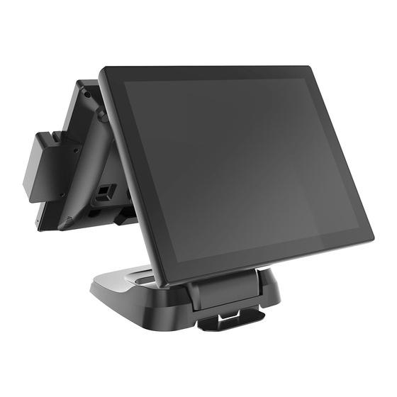
Page 8: Front View
Customer Display 2×20 characters VFD (RS232, option) Operating 5℃ - 40℃ Temperature Environment Operating Humidity 40% - 90% 04. Front View 05. Back View... - Page 9 06. Dimension...
-
Page 10: Part 2. System Installation
07. I/O View Part 2. System Installation 01. Checking the Location for Installation It is important to choose a safe and secure place to install the terminal. •• Choose a desk or table big and strong enough to support the weight of the system and peripherals. - Page 11 •• Make sure a system installed in a well-ventilated place and keep the space free around the system. •• Choose appropriate environmental conditions such as cool and dry places. Avoid humid and dusty places. Also avoid direct sunlight, rapidly changing temperatures, or placing the system near heat sources.
- Page 12 03. Connecting DC power supply cable Connect the DC power cable to the DC power input connector at the bottom of the system. (Adapter 100V - 240V free voltage of the system can be used.)
-
Page 13: Part 3. System Utilization
Tighten the tool-less screw When you need not adjust the angles with the hinge of base, you can tighten the tool-less screw of the base. Step1: Insure the base located in the max angles; Step2: tighten the screw. Part 3. System Utilization 01.POS Driver and Utility Introduction... -
Page 14: Touch Panel
POS Drivers & Other utilities are located in CD Motherboard Touch panel vcredist_2010 should be insatalled for capacitive a.For 32bit OS only install vcredist_2010 x86 b.For 64bit OS should install vcredist_2010 x86 andvcredist_2010 x64 Next install SiwtouchDaemon... - Page 16 02. Dual Monitor Usage Additional monitor can be connected to the VGA connector. This content is written based on Windows 7. The system supports dual monitor system, which is using two monitors for one system. Sub-monitor’s screen can be displayed as a duplication of the main monitor or as an extended screen.
- Page 17 4. On The following dialog window ‘Change display appearance of your display’ ‘Display’ option is set as ‘1|2. Multiple Monitor’ and‘Multiple display (M) option is set as duplicate these displays. (In this case, the dual monitor shows a duplicated screen.) 5.
- Page 18 6. Select <Keep changes> button on ‘Display Settings’ dialog to keep the current settings. 8. If the configuration is finished, click <OK> button to close the ‘Change the...
- Page 19 appearance of your displays’ dialog window.
- Page 20 Part 4. Motherboard Motherboard Layout...
-
Page 21: Connectors& Functions
02. Connectors& Functions Function Connectors 1.PWRT POWER BUTTON 2.DC_IN_24V DC 24V power connector 3. CASH RJ11 connector 4.DC_OUT_12V DC 12V power output 5. VGA VGA connector 4. IVCN LVDS Inverter power connector 6.LAN LAN connector 7. USB1 USB connector 8.USB2 USB connector 9.USB3 USB connector... - Page 22 1. Commonly Jumper Description function Setting Jumper Normal Clean CMOS CMOS 3-pin 2-3 Clear CMOS Setting COM3,COM4 Voltage 6-pin 5-6 RI 1-2 +5V LCD Backlight voltage JPWM 3pin 2-3 +3.3V 1-2 +3.3V LVDS voltage select 3pin 2-3 +5V 2.Display Description Display 1*DB15 Interfac...
- Page 23 LVDS1_N0 LVDS1_CLKP LVDS0_P0 LVDS1_P0 DDC_CLK DDC_DATA LVDS0_N1 LVDS1_N1 LVDS0_P1 LVDS0_N3 LVDS1_P1 LVDS1_N3 LVDS0_P3 LVDS1_P3 LVDS0_N2 LVDS1_N2 1 ● 3● 5● 7● 9● 11● 13● 15● 17● 19● 21● 23● 25● 27● 29● 31● 33● 35● 37● 39● 2 ● 4● 6● 8● 10● 12● 14● 16● 18● 20● 22● 24● 26● 28● 30● 32● 34● 36● 38● 40● LVDS work voltage(1*3 2.54mm):...
- Page 24 3.Audio Description Audio Audio Codec Realtek ALC269 Rear IO Type HP Connector PIN defined XOUTA- XOUTA+ 1■ 2● 3● 4● XOUTB+ XOUTB- Onboard audio PIN defined MIC-R MIC-JD 1■ 2● 3● 4● MIC-L PIN Type 1*4Pin 2.0mm wafer box 4.LAN Description LAN IC RTL811E 10M/100M/1000M...
- Page 25 6.COM Description 4x COM,COM3-COM4 jumper selectable 5V/12V(1A)/RI,other connector type standard COM1-COM2RJ48 COM3 RJ48 RI/5V/12V COM pin COM1-COM3 DB9 COM1-C0M2 DB9...
-
Page 26: Power Connector
COM3 DB9 RI/5V/12V COM4 2X5PIN 2.0mmwafer RI/5V/12V COM3&com4 pin9 12V select Define 1■ 2● Voltage select 3● 4● 5● 6● 7. MINI-PCIE Description MINI-PCIE Connectortype 1*Mini PCIe Port 8.CASH DRAWER CASH DRAWER Description Connectortype RJ11 +24V PIN defined 1.GND 2.CD_OPEN 3.CD_SENSE 4.+24V 5.NC 6.GND 9.Power connector... -
Page 27: Part 4. System Assembly & Disassembly
+24V 4 PIN DC JACK defined: 1. 24V 2. 24V 1●2● 3. GND 4. GND 3●4● 24V DC Part 4. System Assembly & Disassembly... -
Page 28: Hdd Replacement
01. HDD Replacement Step1: Press the place; Step2: Move the HD cover along the arrow; Step3: Release thescrew; Step4: Pull the HD handle and remove the HD. 02. Remove cable cover Step1: Press the switch Step2: pull out cable cover... - Page 29 03. Remove Multi-function card reader Step1: Release the screws Step2: Release the screws Turn over the MSR, Step3: separate the shell of MSR, then remove the cable.
- Page 30 ③ 04. Remove customer display Step1:Rotate customer display to the horizontal position and release thescrew; Step2:Pull off cable terminal, Remove customer display.
- Page 31 05. Remove the second display Step1: Loose the tool-less screw; Step2: Move the display along the arrow; Step3: Remove the display along the arrow.
- Page 32 The cable Assembly Step1: Loose the tool-less screw and remove the shell; Step2: Let the cable into the base from the bottom of base ; Step3: Connect the cables and tidy the cables;...
- Page 33 Step4: Assemble the cable shell, push the position of the red dot with thumb ; Step5: Assemble the base shell and tighten the tool-less screw;...
-
Page 34: Bios Setup
BIOS Set Up Appendix A . Understanding BIOS BIOS provides configuration and set-up information for driving the main board. BIOS values are saved in CMOS ROM on the main board. BIOS (Basic Input and Output System) Set-Up is a menu-oriented software utility which enables a user to configure the system's environmental set-up, system hardware, power saving functions, etc. - Page 35 Cash Drawer This Demo program for POS box CD_SENSE GP23 CD_OPEN GP36 #include "stdio.h" #include "conio.h" #include "graphics.h" #include "string.h" #include "io.h" #define BIT0 0x01 #define BIT1 0x02 #define BIT2 0x04 #define BIT3 0x08 #define BIT4 0x10 #define BIT5 0x20 #define BIT6 0x40 #define BIT7 0x80 #define IO_Base...
- Page 36 int Get_CD_SENSE_Status() if(inportb(CDS_PORT)&BIT3) { delay(100); if(inportb(CDS_PORT)&BIT3) printf("CD_SENSE is Low level stability.\n"); return 1; else printf("CD_SENSE is High level\n"); return 0; main() printf("System ready\n "); /*Set_CD_OPEN High */ Set_CD_OPEN(1); /*Set_CD_OPEN Low */ Set_CD_OPEN(0); while(1) Get_CD_SENSE_Status();...
Need help?
Do you have a question about the HK570 and is the answer not in the manual?
Questions and answers