Table of Contents
Advertisement
Advertisement
Table of Contents

Related Manuals for JTS RU-8011D


Summary of Contents for JTS RU-8011D
- Page 1 PROFESSIONAL CO., LTD www.jts.com.tw 59508-084-01...
- Page 2 Instruction Manual UHF PLL With JTS Ultrasonic Synchronizing Technology...
- Page 3 One year product warranty Equipment Product Model serial number Customer Contact name number Address Purchase date Selling store stamp Be sure to put store stamp and fill in purchase date for the warranty to be effective! Warranty description 1. Be sure to put the warranty label indicating purchase date on the bottom of equipment to ensure your interest in maintenance and service.
-
Page 4: Table Of Contents
Table of Contents 1. Notes for system operations 2. Features 3. Specifications 3-1 UHF PLL single/dual-channel diversity receiver 3-2 UHF PLL hand-held transmitter 3-3 UHF PLL belt-mount transmitter 3-4 Optional condenser microphone 4. Description of parts 4-1 UHF PLL single-channel diversity receiver // 4-2 UHF PLL single-channel diversity receiver // 4-3 UHF PLL dual-channel diversity receiver // 4-4 UHF PLL hand-held transmitter //... -
Page 5: Notes For System Operations
1. Notes for system operations • Before connecting the power, check that the power requirement shown on the unit is the same as the power output on the adaptor supplied. • Do not leave the unit at where the humidity and temperature are high. • Dry your hands before operating the system. -
Page 6: Specifications
3. Specifications 3-1 UHF PLL single/dual-channel diversity receiver Model Frequency Oscillation Phase-locked loop (PLL) Mode Carrier Frequency Range 470~ Remoset Frequency Ultrasonic Diversity Antennas diversity Bandwidth 36MHz Signal/Noise Ratio >105dB(A) Total Harmonic Distortion <0.6%@1KHz (Thd) Receiving Sensitivity -95dBm,S/N>80dB Image Rejection Ratio >80 dB Frequency Response 60Hz~15KHz±2dB... - Page 7 Model Muting Noise muting and tone code locking 1 x balanced XLR jack 2 x balanced XLR 1 x unbalanced ϕ6.3 jack jack Output Port 2 x unbalanced ϕ6.3 jack DC12~15V/300mA 12~15V DC / 500mA Power Supply Dimension (Mm) 212.3mm (W) x 38.3mm (H) x 144mm (L)
-
Page 8: Uhf Pll Hand-Held Transmitter
3-2 UHF PLL hand-held transmitter Model Frequency Oscillation Mode Phase-locked loop (PLL) Carrier Wave Frequency Range 470~60 MHz Remoset Frequency Ultrasonic RF Power Output 10mW/50mW(as per local regulations) RF Stability <±10KHz @ Fc Modulation Frequency Shift ±48KHz Harmonic Radiation <-50dBc Mute, auto off, input level attenuation, sensitivity Functions adjustment, low power indication... -
Page 9: Uhf Pll Belt-Mount Transmitter
3-3 UHF PLL body-pack transmitter Model Fr e q u e n c y O s c i l l a t i o n Phase-locked loop (PLL) Mode Carrier Wave Frequency 470~60 MHz Range Remoset Frequency Ultrasonic RF Power Output 10mW/50mW(as per local regulations) RF Stability <±10KHz @... -
Page 10: Optional Condenser Microphone
3-4 Optional condenser microphone Lavaliere microphone Model CM-501 CM-201i CM-125i 4-pin mini XLR 4-pin mini 4-pin mini XLR Connector 100~15,000 Hz XLR60~15,000 Hz 50~18,000 Hz Frequency Response Cardioid Omni-directivity Polar Pattern Sensitivity (at 1000Hz) -60 ± 3dB -60 ± 3dB -53 ±... - Page 11 Model CM-235i CX-504 Connector 801C4 (4P Mini XLR ) 4P Mini XLR Frequency Response 50~18,000 Hz 30~18,000 Hz Polar Pattern Omni-directional Cardioid -53 ± 3dB -68 ± 3dB Sensitivity (at 1000Hz) 1.8kΩ 680Ω Impedance 130dB 130dB Max. SPL for 1% THD 155mm(W)x 285mm(W)x Dimension(mm)
-
Page 12: Description Of Parts
4. Description of parts 4-1 UHF PLL single-channel diversity receiver // Front panel Rear panel Antenna A Antenna B 100mA 100mA Power: means “ON” and means “OFF” SET: this is for function settings. Push and hold for 2 seconds to enter the setting mode. - Page 13 LCD Display In the non-setting mode, the LCD looks like this: : Audio signal strength : RF signal strength : Antenna A/B : Group / channel : Button lock engaged : Receiver mute...
-
Page 14: Uhf Pll Single-Channel Diversity Receiver
4-2 UHF PLL single-channel diversity receiver // Front panel Rear panel : See page 8. Female BNC antenna port: the 50Ω BNC antenna is connected here. It also provides a booster power of 12~15 DC / 100mA for an external antenna booster with extension cable. - Page 15 LCD Display In the non-setting mode, the LCD looks like this: : Audio signal strength : RF signal strength : Antenna A/B : Transmitter battery level : Group/channel : Volume : Button lock : Receiver mute : Output attenuation : Frequency...
-
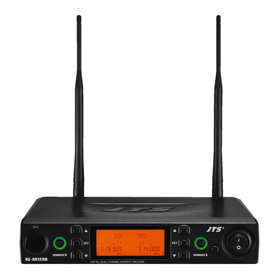
Page 16: Uhf Pll Dual-Channel Diversity Receiver
4-3 UHF PLL dual-channel diversity receiver // Front panel Rear panel : See page 8. Female BNC antenna port: the 50Ω BNC antenna is connected here. It also provides a booster power of 12~15 DC / 100mA for an external antenna amplifier for extended receiving range. - Page 17 LCD Display In the non-setting mode, the LCD looks like this: : Audio signal strength : RF signal strength : Antenna A/B : Transmitter battery level : Frequency (group/channel) : Receiver mute : Output attenuation : Frequency...
-
Page 18: Uhf Pll Hand-Held Transmitter
4-4 UHF PLL hand-held transmitter // Power: push to turn the transmitter on. When the transmitter is on, push and hold for 2 seconds to turn it off. Mute: while the transmitter is on, switch Mute up to talk and down to mute. If the transmitter is off, switch the Mute up to turn the unit on. -
Page 19: Uhf Pll Hand-Held Transmitter
4-5 UHF PLL hand-held transmitter // Power: push to turn the transmitter on. When the transmitter is on, push and hold for 2 seconds to turn it off. Mute: while the transmitter is on, switch Mute up to talk and down to mute. If the transmitter is off, switch the Mute up to turn the unit on. -
Page 20: Uhf Pll Body-Pack Transmitter
4-6 UHF PLL body-pack transmitter // Mute/Power: push once to turn the unit on. While the unit is on, push once to mute and push again to talk. Push and hold for 2 seconds to turn off. Ultrasonic receiving unit: it receives the pairing signals from the ultrasonic transmission unit at the receiver end. -
Page 21: Uhf Pll Body-Pack Transmitter
4-7 UHF PLL body-pack transmitter // Mute/Power: push once to turn the unit on. While the unit is on, push once to mute and push again to talk. Push and hold for 2 seconds to turn off. Ultrasonic receiving unit: it receives the pairing signals from the ultrasonic transmission unit at the receiver end. -
Page 22: Accessories
4-8 Accessories AC/DC adaptor Switching Power Supply(100V~240V , 50~60Hz) AC IN: AC100~240V/50~60Hz DC OUT: DC12V/0.5A Option AF output cable (with Φ6.3 plug at both ends) 4-9 Optional Condenser Microphone Lavaliere Microphone // CM-501 CM-201i CM-125i Clip CM-501 CM-201i CM-125i 4 Pin Mini XLR Windscreen... - Page 23 Headset Microphone // CM-214i CM-214Ui CM-214ULi CM-235i CX-504 Gooseneck Adjustable headband Headband 4 Pin Mini XLR Windscreen CM-214i CM-214Ui CM-214ULi Standard : 4 Pin Mini XLR 3 Pin Mini XLR 3.5 Stereo Plug CM-504 CM-235i...
- Page 24 Ear-hook Microphone // CM-801 CM-804i CM-8015 CM-825i Boom Adjustable Headband Adjustable ear hook Detchable Cable CM-801 Cable Clip Windscreen 4 Pin Mini XLR 3 Pin Mini XLR Option 3.5 Stereo Plug Option 4Pin Hirose connecter Option CM-804i CM-8015 CM-825i...
-
Page 25: Connecting
5. Connecting 5-1 How to connect the receiver 1. Connect the audio output of receiver to mixer or amplifier : The XLR output jack or 6.3mm unbalance output jack can be selected to connect the AF output to a mixer or amplifier. :... - Page 26 Step1 Amplifie Step 2 AC/DC adaptor Wall socket...
-
Page 27: Transmitter Installation
5-2 Transmitter installation // The Mute button on the hand-held unit also triggers the power-on. That’s why the unit is on as soon as the batteries are replaced. Therefore, if you do not wish to turn on after changing the batteries, keep the Mute switch on mute. 1. -
Page 28: Instructions For Use
6. Instructions for use 6-1 How to use // Parameter setting Push and hold the “SET” button to enter the setting mode. ◎ Group / channel setting G: group Select default group 1~6 CH : channel Select default channel, 1~22 Select the group when “G”... - Page 29 ◎ Microphone input sensitivity Normal sensitivity SE A:+15dB SE 9:+12 dB SE 8:+9dB SE 7:+6dB SE 6:+3 dB Normal default sensitivity SE 5:0 dB SE 4:-3 dB SE 3:-6 dB SE 2:-9 dB SE 1:-12 dB SE 0:-15 dB 20dB SE AA:-5 dB attenuation SE A9:-8 dB...
- Page 30 Volume adjustment In non-setting mode, adjust the volume from 0 to 31dB using the▲/▼button. The minimum volume is 0dB. ● The maximum volume is 31dB. ● The default is 25dB. ● Minimum volume at 0db; maximum volume at 31dB Pairing Once the parameters are set, push the “...
-
Page 31: How To Use
6-2 How to use // Parameter setting Push and hold the “SET” button to enter the setting mode. Push the ▲/▼ button to choose to set RX (receiver) or TX (transmitter). When RX receiver is selected: ◎ FREQ: frequency setting In 1MHz Select frequency with ▲/▼... - Page 32 ◎ Audio output attenuation (XLR) At oFF No attenuation at audio output At on 20dB attenuation at audio ouput This function is deactivated. ◎ SQ Receiving sensitivity -5~+10dB; -5 is the maximum sensitivity. select +10 is the minimum sensitivity. SQ with The defaul is 0.
- Page 33 ◎ATOF: Automatic microphone off countdown under mute status AO OF This function is deactivated AO 1 1 minute countdown to turn off AO 10 10 minute countdown to turn off AO 30 30 minute countdown to turn off This function is deactivated. ◎RFP: RF microphone power The transmitter comes with 2 stages of RF power output (as per local regulations).
-
Page 34: How To Use
6-3 How to use // Parameter setting Push and hold the “SET” button to enter the setting mode. Push the ▲/▼ button to choose to set RX (receiver) or TX (transmitter). When RX receiver is selected: ◎ FREQ: frequency setting In 1MHz Select frequency with ▲/▼... - Page 35 ◎ Audio output attenuation (XLR) At oFF No attenuation at audio input At on 20dB attenuation at audio input (depending on whether the transmitter is provided with the corresponding function) . The function is activated with 20dB of audio input attenuation. ◎...
- Page 36 ◎ ATOF: Automatic microphone off countdown under mute status This function is deactivated 1 minute countdown to turn off 10 minute countdown to turn off 30 minute countdown to turn off This function is deactivated. ◎ RFP: RF microphone power The transmitter comes with 2 stages of RF power output (as per local regulations).
-
Page 37: How To Use
6-4 How to use // Parameter setting Parameters, including group, channel,microphone input sensitivity, auto off countdown and RF power, are set at the receiver end and synchronized via Pairing See page 26. Indicators Green Battery > 2V Flashing green Microphone mute Battery ≤... - Page 38 6-5 How to use // Parameter setting ◎ FREQ: frequency setting In 1MHz Select frequency with ▲/▼ In 0.025MHz Select frequency with ▲/▼ Select the number of frequency first in MHz and then in 0.025MHz. ◎ Group / channel G: group Select default group 1~6 CH: channel Select default channel, 1~22...
- Page 39 ◎ Microphone input sensitivity Normal GAIN:+15dB sensitivity GAIN:+12dB GAIN:+9dB GAIN :+6dB GAIN:+3dB GAIN:0dB GAIN:-3dB It shows the sensitivity is now at GAIN 0dB GAIN:-6dB (default). GAIN:-9dB GAIN:-12dB GAIN:-15dB ◎ RFP: RF microphone power rFP Lo 10mW rFP Hi 50mW The RF output is LOW. The RF output is Hi.
-
Page 40: Notes For The Product
7. Notes for the product For the best signal receiving quality, always keep the receiver within 3m of the transmitter. The receiver and transmitter shall be away from other metal objects, preferably 50cm or farther. Do not point the microphone directly to a speaker, or there will be feedbacks. It is recommended to hold the transmitter (microphone) at the middle section for the best pickup. - Page 41 FCC Statement FCC INFORMATION The equipment has been tested and found to comply with the limits for a Class B Digital Device, pursuant to part 15 of the FCC Rules. These limits are designed to provide reasonable protection against harmful interference in a residential installation. This equipment generates, uses and can radiate radio frequency energy and, if not installed and used in accordance with the instruction, may cause harmful interference to radio communication.
Need help?
Do you have a question about the RU-8011D and is the answer not in the manual?
Questions and answers