Isotra Cetta 50 Technical Manual
Exterior blinds
Hide thumbs
Also See for Cetta 50:
- Control and maintenance manual (7 pages) ,
- Technical manual (80 pages)
Table of Contents
Advertisement
Advertisement
Table of Contents

Subscribe to Our Youtube Channel
Related Manuals for Isotra Cetta 50


Summary of Contents for Isotra Cetta 50
- Page 1 Technical manual eXTeRiOR BlinDS...
- Page 2 Control - handle Control – motor A mark symbolising long tradition, inestimable investment into development, the use of quality materials, state-of the-art technologies, reliable work from hundreds of employees and numerous other parameters, constituting one entity – the final product of ISOTRA.
- Page 3 EXTERIOR BLINDS CE Product Marking All exterior blinds of ISOTRA a.s. comply with the standard ČSN EN 13659+A1:2009 European Marking of CE Compliance – marking on products ISOTRA a.s. Bílovecká 2411/1, 746 01 Opava EN 13659:2015 ZETTA 90 CPR 008/2017 Exterior sun visor Wind resistance: 0 –...
- Page 4 Setta 65 - channel Essential characteristics Performance Wind resistance Width of construction hole L (mm) L <= 2 000 2 000 < L <= 3 000 3 000 < L <= 4 000 4 000 < L <= 4 500 Standard EN/Beaufort 13659 Beaufort...
- Page 5 EXTERIOR BLINDS Zetta 70 - wire Essential characteristics Performance Wind resistance Width of construction hole L (mm) L <= 2 000 2 000 < L <= 3 000 3 000 < L <= 4 000 4 000 < L <= 4 500 4 500 < L <= 4 800 4 800 < L <= 5 000 5 000 < L <= 6 000 Standard EN/Beaufort 13659 Beaufort 13659 Beaufort 13659 Beaufort 13659 Beaufort 13659 Beaufort 13659 Beaufort 13659 Beaufort Wind resistance class...
- Page 6 Cetta 80 Flexi - wire Essential characteristics Performance Wind resistance Width of construction hole L (mm) L <= 2 000 2 000 < L <= 2 500 2 500 < L <= 3 000 3 000 < L <= 3 400 3 400 <...
- Page 7 6 Nm Motor Type min. max. max. Cord Handle Motor Guidance Weight (kg per m (kg per m Weight (kg) (kg per m Cetta 50 400/600** 3150 3000 wire / channel 0,76 0,087 Cetta 60 Flexi 4000 4000 wire / channel 1,31...
- Page 8 PRODUCT TOLERANCES Manufacturer: ISOTRA a.s., Bílovecká 2411/1, 746 01 Opava, ID: 47679191 Product: EXTERNAL BLINDS The review should help you to recognize the permissible limits of compliance and incompliance. At the same time the sheet will help you with reasoning as regards any unjust claims of the clients.
- Page 9 EXTERIOR BLINDS Calculation of solar and light transmittance The standard CSN EN 13363-1+A1 Solar protection devices combined with glazing - Calculation of solar and light transmittance defines a simplified method of calculation of a sun protection device combined with glazing based on thermal transmittance and total solar transmittance through glazing, and on light transmittance and reflectivity of a sun protection device for the evaluation of total solar transmittance.
- Page 10 )-1 = (1/2,9+1/5+1/10)-1 = 1,55 = τ *g+α *G/G +τ *(1-g)*G/G = 0,137 /g = 0,137/0,76 = 0,18 Solar and light transmittance according to CSN EN 13363-1+A1 for selected products of ISOTRA a.s. Slat colour Reflection (%) Absorption (%) gtot RAL 7038 0,064 0,107...
- Page 11 1200 1300 1400 1500 1600 1700 1800 Cetta 50 - channel Cetta 50 - wire Cetta 65 Cetta 60 Flexi - channel Cetta 60 Flexi - wire Cetta 80 Flexi - channel Cetta 80 Flexi - wire Cetta 100 Flexi - channel...
- Page 12 Titan 90 (Motor control) Note: For Cetta 50 (motor), the coiling height will change by +40 mm. For Cetta 65, 80, 80-Flexi and Zetta 70 a 90 (motor), the coiling height will change by +20 mm. The coiling heights are approximate values which can deviate positively or negatively for technical reasons.
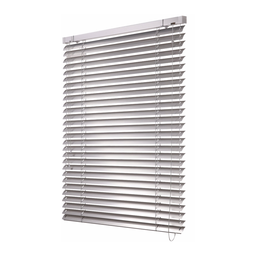
- Page 13 EXTERIOR BLINDS Cetta 50 Suitable for shading small areas Optional assembly in interior Electrical control option ...
-
Page 14: Basic Product Specification
P 532 P 506 YX 00041 P 509/1 P 527 P 502/1 P 508 CETTA 50 - CORD 2-00152-XXXX-G P 525/1 Control CETTA 50 - ŠŇŮRA 2-00152-XXXX Used for pulling the blind up and down and setting the slat Cord - a plastic cord bushing is installed on the window frame from the interior, which protects the cord against abrasion. - Page 15 EXTERIOR BLINDS Cetta 50 - cord (2-00152-5001) Position Item name Business name Drawing number Head rail 40x40 P 528 6-001277-xxxx Bottom rail - 50 mm P 508 6-001230-xxxx Bearing C50 - without ball cord P 225/1 2-00365-0000 End stop 40x40...
- Page 16 P 509/1 P 529/1 P 150/1 SK 52 P 531 P 506 P 502/1 P 508 CETTA 50 - HANDLE 2-00151-XXXX-H P 525/1 CETTA 50 - KLIKA 2-00151-XXXX-H Control - handle, channel 56x58 P 001/1 P 001/2 P 041 P 025/35...
- Page 17 EXTERIOR BLINDS Cetta 50 - handle (2-00151-5001) Position Item name Business name Drawing number Head rail, Fe 56x58 P 001/1 3-00166-PU22 Head rail, Al 58x60 P 001/2 7-301180-0000 End stop 56x58 P 041 2-00048-9004 Bearing C35/C50 P 025/35 2-01100-9004 Gearing plastic 4 mm hexagonal, STS-extended...
- Page 18 P 529/1 P 505 P 531 P 509/1 P 506 P 502/1 P 508 P 525/1 CETTA 50 - MOTOR 2-00301-XXXX-J CETTA 50 - MOTOR 2-00301-XXXX-J Control - motor, channel 56x58 P 001/1 221, 222 P 001/2 P 073 P 313...
- Page 19 EXTERIOR BLINDS Cetta 50 - motor (2-00301-5001) Position Item name Business name Drawing number Head rail, Fe 56x58 P 001/1 3-00166-PU22 Head rail, Al 58x60 P 001/2 7-301180-0000 Bearing C35/C50 P 025/35 2-01100-9004 Motors (SOMFY) EX. BLINDS P 073 2-00512-0000 Motors (GEIGER) EX.
- Page 20 CETTA 50 EXTERIOR BLIND DIAGRAM HORIZONTAL SECTION HANDLE CONTROL...
- Page 21 EXTERIOR BLINDS CETTA 50 EXTERIOR BLIND DIAGRAM SCHÍMA VENKOVNŘ �ALUZIE CETTA 50 VERTIKÁLNŘ ŽEZ OVLÁDÁNŘ KLIKOU VERTICAL SECTION HANDLE CONTROL...
- Page 22 CETTA 50 EXTERIOR BLIND DIAGRAM SCHÍMA VENKOVNČ �ALUZIE CETTA 50 VERTICAL SECTION ENDLESS CORD VERTIKÁLNČ ŮEZ OVLÁDÁNČ NEKONEŇNOU ŽŠ�ROU...
- Page 23 EXTERIOR BLINDS Cetta 65,80,80 Slim, 60/80/100 Flexi Bottom rail made of extruded aluminum Higher slat rigidity Electrical control option Slim - low roll height - specific folding of slats ...
-
Page 24: Standard Dimensions
Standard: Standard: According to current grey Basic design – anod- grey grey galvanized steel plate anodized aluminum ISOTRA a.s. scheme ized black black natural (Al profil) Varnished in RAL Other RAL colors colors, DECORAL* Other RAL colors sprayed , DECORAL*... - Page 25 EXTERIOR BLINDS Cetta 65, Cetta 80 klika (2-00171-XXXX) Position Item name Business name Drawing number 10 - 18 Head rail 56x58 Fe P 001/1 3-00166-PU22 10 - 18 Head rail 58x60 Al P 001/2 3-00166-PU22 10 - 18 End stop 56x58 P 041 2-00048-0000 10 - 18...
- Page 26 Standard: Standard: According to current grey Basic design - anod- grey grey Galvanized steel plate natural anodized aluminium ISOTRA a. s. scheme black ized black black (Al profil) Varnished in RAL Other RAL colors sprayed, Other RAL colors colors, DECORAL*...
- Page 27 EXTERIOR BLINDS Cetta 65, Cetta 80 motor (2-00172-XXXX) Position Item name Business name Drawing number 10-18 Head rail 56x58 Fe P 001/1 3-00166-PU22 10-18 Head rail 58x60 Al P 001/2 7-301180-0000 10-18 Motors (ELERO) EX. BLINDS P 096 2-00648-0000 10-18 Motors (SOMFY) EX.
- Page 28 Cetta 60 Flexi Basic Product Specification 10-18 10-18 P 001/1 P 001/2 10-18 P 041 P 025/31 P 023/1 P 025/50 P 002/7 221, 222 P 002/8 P 056/2 P 313 P 077 10-18 10-18 P 006 P 045/9 P 045/5 P 045/6 10-18 O 105...
- Page 29 Standard: According to current grey Standard: anodized grey grey Galvanized steel plate Galvanized steel plate ISOTRA a. s. scheme Other RAL colors black black Other RAL colors sprayed, Other RAL colors sprayed, sprayed We do not make atypical designs. Standard dimensions...
- Page 30 Cetta 80 Flexi Basic Product Specification 10-18 10-18 P 001/1 P 001/2 10-18 P 041 P 025/31 P 023/1 P 025/50 P 002/7 221, 222 P 002/8 P 077 P 313 P 056/2 10-18 10-18 P 006 P 045/9 P 045/5 P 045/6 10-18 O 118...
- Page 31 Other RAL sprayed Other RAL sprayed from ISOTRA a. s. Other RAL sprayed DECORAL* DECORAL* *Maximum dimension 4000mm. Cetta 80 Flexi - handle (2-00135-XXXX) Position Item name Business name...
- Page 32 Cetta 100 Flexi Basic product specifikation 10-18 10-18 P 001/1 P 001/2 10-18 P 041 P 025/31 P 023/1 P 025/50 P 002/7 221, 222 P 002/8 P 056/2 P 077 P 313 10-18 10-18 P 006 P 045/9 P 045/5 P 045/6 10-18 O 104...
- Page 33 103,5 galvanized sheet elox sampler elox black black Other RAL sprayed Other RAL sprayed from ISOTRA a. s. Other RAL sprayed LAMELA 100 FLEX P 317 3-03196-XXXX-0 LIŠTA DOLNÍ C100 FLEX P 012/27 3-03194-XXXX-0 LIŠTA DOLNÍ C100 FLEX P 012/27...
- Page 34 CETTA 80, CETTA 65 EXTERIOR BLIND DIAGRAM VERTICAL SECTION HANDLE CONTROL Slat guidance in guiding channel.
- Page 35 EXTERIOR BLINDS CETTA 80, CETTA 65 EXTERIOR BLIND DIAGRAM VERTICAL SECTION HANDLE CONTROL Slat guidance using a steel wire...
-
Page 36: Motor Control
CETTA 65 EXTERIOR BLIND DIAGRAM HORIzONTAL SECTION MOTOR CONTROL DISTANCE OF GUIDING CHANNEL... - Page 37 EXTERIOR BLINDS CETTA 60 - FLEXI EXTERIOR BLIND DIAGRAM VERTIKÁLNŘ ŽEZ VERTICAL SECTION MOTOR CONTROL OVLÁDÁNŘ MOTOREM min. 120...
- Page 38 CETTA 60 - FLEXI EXTERIOR BLIND DIAGRAM VERTICAL SECTION MOTOR CONTROL VERTIKÁLNŘ ŽEZ OVLÁDÁNŘ KLIKOU min. 100 Handle Handle...
- Page 39 EXTERIOR BLINDS CETTA 60 - FLEXI EXTERIOR BLIND DIAGRAM VERTICAL SECTION MOTOR CONTROL VERTIKÁLNŘ ŽEZ OVLÁDÁNŘ MOTOR min. 100...
- Page 40 CETTA 60 - FLEXI EXTERIOR BLIND DIAGRAM VERTICAL SECTION MOTOR CONTROL VERTIKÁLNŘ ŽEZ OVLÁDÁNŘ KLIKOU min. 100 Handle Handle...
- Page 41 EXTERIOR BLINDS CETTA 80 - FLEXI EXTERIOR BLIND DIAGRAM VERTICAL SECTION MOTOR CONTROL VERTIKÁLNŘ ŽEZ OVLÁDÁNŘ MOTOREM min. 120...
- Page 42 CETTA 80 - FLEXI EXTERIOR BLIND DIAGRAM VERTIKÁLNŘ ŽEZ OVLÁDÁNŘ KLIKOU VERTICAL SECTION MOTOR CONTROL min. 120 Handle Handle...
- Page 43 EXTERIOR BLINDS CETTA 80 - FLEXI EXTERIOR BLIND DIAGRAM VERTIKÁLNŘ ŽEZ OVLÁDÁNŘ MOTOREM VERTICAL SECTION MOTOR CONTROL min. 120...
- Page 44 CETTA 80 - FLEXI EXTERIOR BLIND DIAGRAM VERTIKÁLNŘ ŽEZ VERTICAL SECTION MOTOR CONTROL OVLÁDÁNŘ KLIKOU min. 120 Handle Handle...
- Page 45 EXTERIOR BLINDS CETTA 100 - FLEXI EXTERIOR BLIND DIAGRAM VERTIKÁLNŘ ŽEZ VERTICAL SECTION MOTOR CONTROL OVLÁDÁNŘ MOTOREM min. 140...
- Page 46 CETTA 100 - FLEXI EXTERIOR BLIND DIAGRAM VERTIKÁLNŘ ŽEZ VERTICAL SECTION MOTOR CONTROL OVLÁDÁNŘ KLIKOU min. 140 Handle Handle...
- Page 47 EXTERIOR BLINDS CETTA 100 - FLEXI EXTERIOR BLIND DIAGRAM VERTIKÁLNŘ ŽEZ VERTICAL SECTION MOTOR CONTROL OVLÁDÁNŘ MOTOR min. 140...
- Page 48 CETTA 100 - FLEXI EXTERIOR BLIND DIAGRAM VERTIKÁLNŘ ŽEZ OVLÁDÁNŘ KLIKOU VERTICAL SECTION MOTOR CONTROL min. 140 Handle Handle...
- Page 49 EXTERIOR BLINDS Setta 65, 90 Elegant slat shape „S“ Bottom rail made of extruded aluminium Electrical control option Excellent thermo-regulating effect Rubber pressed in along the entire slat width ...
-
Page 50: Basic Product Specification
Color Standard: Standard: According to current Standard: grey grey grey galvanized steel plate anodized aluminum ISOTRA a.s. scheme anodized black black black natural (Al profil) Other RAL colors Other RAL colors Other RAL colors sprayed, DECORAL* sprayed, DECORAL* sprayed, DECORAL*... - Page 51 EXTERIOR BLINDS Setta 65,90 - handle (2-00812-XXXX) Position Item name Business name Drawing number 10-18 Head rail Fe P 001/1 3-00166-PU22 10-18 Upper head rail P 001/2 7-301180-0000 10-18 Bearing C80 / C65 / S65 / Z70 P 025/31 2-01098-9004 10-18 Bearing Z90 / S90 P 025/32...
- Page 52 Fe/PVC Color Standard: Standard: According to current Standard: grey grey grey galvanized steel plate anodized aluminum ISOTRA a.s. scheme anodized black black black natural (Al profil) Other RAL colors Other RAL colors Other RAL colors sprayed sprayed sprayed Specification Setta 90...
- Page 53 EXTERIOR BLINDS Setta 65,90 - motor (2-00813-XXXX) Position Item name Business name Drawing number 10-18 Head rail Fe P 001/1 3-00166-PU22 10-18 Upper head rail P 001/2 7-301180-000 10-18 Bearing C65, C80, Z70, S65 P 025/31 2-01098-9004 10-18 Bearing Z90/S90 P 025/32 2-01099-9004 10-18...
- Page 54 SETTA 65,90 EXTERIOR BLIND DIAGRAM SCHÉMA VENKOVNÍ ŽALUZIE SETTA 65,90 VERTICAL SECTION HANDLE CONTROL VERTIKÁLNÍ ŘEZ OVLÁDÁNÍ KLIKOU min. 140 90° HANDLE 45° HANDLE...
- Page 55 EXTERIOR BLINDS SETTA 65/90 EXTERIOR BLIND DIAGRAM SCHÉMA VENKOVNÍ ŽALUZIE SETTA 65,90 VERTICAL SECTION HANDLE CONTROL VERTIKÁLNÍ ŘEZ OVLÁDÁNÍ KLIKOU min. 140 90° HANDLE 45° HANDLE...
- Page 56 SETTA 65,90 EXTERIOR BLIND DIAGRAM SCHÉMA VENKOVNÍ ŽALUZIE SETTA 65,90 VERTICAL SECTION HANDLE CONTROL VERTIKÁLNÍ ŘEZ OVLÁDÁNÍ MOTOREM min. 140...
- Page 57 EXTERIOR BLINDS SETTA 65/90 EXTERIOR BLIND DIAGRAM SCHÉMA VENKOVNÍ ŽALUZIE SETTA 65,90 VERTICAL SECTION HANDLE CONTROL VERTIKÁLNÍ ŘEZ OVLÁDÁNÍ MOTOREM min. 140...
- Page 58 SETTA 65,90 EXTERIOR BLIND DIAGRAM VERTICAL SECTION HANDLE CONTROL DISTANCE OF GUIDING CHANNEL...
- Page 59 EXTERIOR BLINDS Zetta 70, 90 High degree of shading Thermo-regulating and protecting effect Outside noise level reduction Bottom rail made of extruded aluminum Electrical control option Rubber pressed in along the entire slat width ...
- Page 60 Color Standard: Standard: According to current Standard: grey grey grey galvanized steel plate anodized aluminum ISOTRA a.s. scheme anodized black black black natural (Al profil) Other RAL colors Other RAL colors Other RAL colors sprayed, DECORAL* sprayed, DECORAL* sprayed, DECORAL*...
- Page 61 EXTERIOR BLINDS Zetta 70,90 - handle (2-00157-7001/9001) Position Item name Business name Drawing number 10-18 Head rail Fe P 001/1 3-00166-PU22 10-18 Upper head rail P 001/2 7-301180-0000 10-18 Bearing C80 / C65 / S65 / Z70 P 025/31 2-01098-9004 10-18 Bearing Z90 / S90 P 025/32...
- Page 62 Color Standard: Standard: According to current Standard: grey grey grey galvanized steel plate anodized aluminum ISOTRA a.s. scheme anodized black black black natural (Al profil) Other RAL colors Other RAL colors Other RAL colors sprayed, DECORAL* sprayed, DECORAL* sprayed, DECORAL*...
- Page 63 EXTERIOR BLINDS Zetta 70,90 - motor (2-00158-7001/9001) Position Item name Business name Drawing number 10-18 Head rail Fe P 001/1 3-00166-PU22 10-18 Upper head rail P 001/2 7-301180-000 10-18 Bearing C65, C80, Z70, S65 P 025/31 2-01098-9004 10-18 Bearing Z90/S90 P 025/32 2-01099-9004 10-18...
- Page 64 ZETTA 70, ZETTA 90 EXTERIOR BLIND DIAGRAM VERTICAL SECTION HANDLE CONTROL Slat guidance in guiding channel...
- Page 65 EXTERIOR BLINDS ZETTA 70, ZETTA 90 EXTERIOR BLIND DIAGRAM VERTICAL SECTION HANDLE CONTROL Slat guidance in guiding channel min. 133 90 (70)
- Page 66 ZETTA 70, ZETTA 90 EXTERIOR BLIND DIAGRAM VERTICAL SECTION HANDLE CONTROL Slat guidance using steel wire...
- Page 67 EXTERIOR BLINDS ZETTA 70, ZETTA 90 EXTERIOR BLIND DIAGRAM VERTICAL SECTION HANDLE CONTROL Slat guidance using steel wire min. 133 90 (70)
- Page 68 ZETTA 70, ZETTA 90 EXTERIOR BLIND DIAGRAM VERTICAL SECTION HANDLE CONTROL DISTANCE OF GUIDING CHANNEL...
- Page 69 EXTERIOR BLINDS ZETTA 70, ZETTA 90 EXTERIOR BLIND DIAGRAM VERTICAL SECTION HANDLE CONTROL Slat guidance in double guiding channel...
- Page 70 ZETTA 70, ZETTA 90 EXTERIOR BLIND DIAGRAM VERTICAL SECTION HANDLE CONTROL Slat guidance using steel wire min. 133 (70)
- Page 71 EXTERIOR BLINDS ZETTA 70, ZETTA 90 EXTERIOR BLIND DIAGRAM VERTICAL SECTION HANDLE CONTROL Slat guidance in guiding channel DISTANCE OF GUIDING CHANNEL...
- Page 72 Shapes of exterior blind slats Cetta 50 Cetta 60 Flexi Cetta 65 Cetta 80 + Cetta 80 Slim LAMELA 60 FLEX P 316 3-03195-XXXX-0 LAMELA 60 FLEX P 316 3-03195-XXXX-0 Cetta 80 Flexi Setta 65 Setta 90 Cetta 100 Flexi...
- Page 73 EXTERIOR BLINDS 2-01072-XXXX-0 SLAT C50 - SET P 529 Cetta 50 Posi- Item Business Drawing tion name name number Al Slat P 529 2-01072-XXXX-0 Slat insert of guide P 506 2-01072-XXXX-0 cord End guidance L+R P 033/1 2-01072-XXXX-0 P 529...
- Page 74 2-01056-XXXX-1 SLAT C80 - SET Cetta 80 Posi- Item Business Drawing O 103 tion name name number Al Slat O 103 2-01056-XXXX-1 Plastic insert Slim P 075/1 2-01056-XXXX-1 End guidance for P 033/2 2-01056-XXXX-1 slat “C” L+R (plastic) End guidance for P 033/21 2-01056-XXXX-1 slat “C”...
- Page 75 P 033/1 P 033/31 EXTERIOR BLINDS P 033/32 O 101 2-00687-XXXX-B SLAT S65 - SET Setta 65 P 033/1 Posi- Item Business Drawing P 033/31 tion name name number P 033/32 O 101 Al slat O 101 2-00687-XXXX-B P 200 Slat rubber P 199 2-00687-XXXX-B...
- Page 76 SLAT Z90 - SET 2-00514-XXXX-C Zetta 90 P 033/1 Posi- Item Business Drawing P 033/31 P 033/32 tion name name number O 124 Al slat O 124 2-00514-XXXX-C Slat rubber P 198 2-00514-XXXX-C P 198 Connecting hook P 200/30 2-00514-XXXX-C End guidance for P 033/1 2-00514-XXXX-C...
- Page 77 EXTERIOR BLINDS Control for Cetta, Setta, Zetta Handle (2-00339-0000) The controls serve for pulling the blind up and down and setting the slat. The rod control mechanism is to be passed to the interior at an angle of 45° and 90° using a bushing and a hexagonal or square rod. Rod colour versions: white;...
- Page 78 PROSÍM O ZASLÁNÍ OBRÁZKU Převodovka P 045/9 (6-010260) Plastic gearing with hexagonal aperture - interior Gearing with hexagonal aperture, extended (STS) (Cetta 35, Cetta 50) P045/4 (6-008115) P 517/2 (6-001250-0002) Gearing with hexagonal aperture for handle control Gearing extension (Cetta 35, Cetta 50)
-
Page 79: Safety Instructions
EXTERIOR BLINDS Gearing Shift Scheme "0" - (0 - ∞) + (0 - 90) The gearing position (possible shift) in the head rail depends on the specific mounting of frame window, reveal. The gearing axis is the distance of the gearing center axis from the outer edge of guiding channel, or outer edge of slat in the case of the steel wire guidance. Safety Instructions: •... -
Page 80: Motor Control
Motor control Motor control Motor controls serve for pulling the blind up and down and setting the slat. Motor controls allow selecting the control by the sun/wind sensor, remote control, or switch. It is possible to control several blinds at once depending on their dimensions. -
Page 81: Important Instructions
EXTERIOR BLINDS Motor control Motor Wiring Diagram RTS Motor Wiring Diagram 1 - Blue 2 - Black 3 - Brown 1 - neutral wire (N) 1 - neutral wire (N) PE - Yellow-green 2 - phase wire (up) 2 - phase wire (L) 3 - phase wire (down) 3 - not connected PE - ground wire... -
Page 82: Setting Adjustment
Setting Adjustment When setting the end position, the motor speed is set. If the end position is not set correctly, or if the Venetian blind behavior, and thus the bottom rail end position, has changed due to ambient effects and increased friction, the required end position must be re-set according to the above-described procedure. - Page 83 EXTERIOR BLINDS Guidance – Wire Guide types for wire-guided blinds (Cetta 35, Cetta 50, Cetta 65, Cetta 80, Cetta 80-Flexi) Corner wire guide, 25 - 46 mm P031/6 (2-00822) Corner wire guide, 39 - 60 mm P 031 (2-00195) Corner wire guide, 49 - 70 mm P 031/1 (2-00137)
- Page 84 Wire guide - attachment methods Channel 56 x 58 Channel 40x40 NAPÍNÁNÍ LANKA...
- Page 85 EXTERIOR BLINDS Wireholder Fe P002/7 (2-01128) Wireholder Al P002/8 (2-01294) (for head rail 56x58) (for head rail 58x60) Head rail section hanger Fe for cord guide (2-00685) (for Head Rail 56x58) Guide P534/1 (7-301796) Shutter with holder (2-00684) for negative (-) axis (-10 ≥ -32) for positive (+) axis (+11 ≥...
- Page 86 Guidance - Guiding Channel Guiding channels applies to: Cetta 50, Cetta 60 Flexi, Cetta 65, Cetta 80, Cetta 80-Flexi, Cetta 80-Slim, Zetta 70, Zetta 90, Setta 65, Setta 90 P 018/2 P 018/10 P 018/2 P 016/1 P 018/10 P 017/1...
- Page 87 EXTERIOR BLINDS Single Guiding Channel P 018/2 (7-302122) Single Guiding Channel P 018/10 (7-302363) for installation in lining (without use of ejector) for installation in lining (without use of ejector) Self-Supporting Guiding Head rail section hanger Shutter P 002/41 (2-00588) Channel P 016/1 (7-302121) with holder P 002/4 for guide channel P 016/1...
- Page 88 Single-Sided Round Channel P 018/7 (7-302154) Double-Sided Round Guiding Channel P 017/7 (7-302155) Guiding Channel under Plastering P 018/31 (7-302234) Guiding Channel under Plastering P 018/51 (7-301781, Al) with insert P 018/3 (3-01418) with insert P 018/5 (7-301782, PVC) P 018/31 29±1 P 018/3 23±1...
- Page 89 EXTERIOR BLINDS Guiding Channel Holders For guiding channel P 017/1, P 018/10 P 021/11 35 - 37,5 P 021 55 - 74 P 021/1 75 - 102 P 021/2 103 - 154 Telescopic guiding channel holder , P021/3 (2-00401) Telescopic guiding channel holder, P021/4 (2-00402) for guiding channel P 017/1, P 017/5, P 018/10, P 018/4 for guiding channel P 017/1, P 017/5, P 018/10, P 018/4 DRŽÁKY...
- Page 90 Guiding Channel Holders Telescopic guiding channel holder, P050/01 (2-01027), P050/02 (2-01028), P050/03 (2-01029) for guiding channel P017/1 a P018/10 20,5 P 050/01 50 - 60 0,15 12,5 0,05 P 050/02 10,0 60 - 70 P 050/03 70 - 90 20,5 Telescopic guiding channel holder, P050/04 (2-01030), P050/05 (2-01031), P050/06 (2-01032), P050/07 (2-01033), P050/08 (2-01034), P050/09 (2-01035), P050/10 (2-01036) for guiding channel P017/1 a P018/10 DRŽÁKY VODÍCÍCH LIŠT...
- Page 91 EXTERIOR BLINDS Guiding Channel Holders Guiding channel corner bracket exterior 70 -80 P 098/0 (2-01150-XXXX-0) For extension of 70mm is the measured width 39mm bigger. With each extension of 1 mm, increases also the width by 1 mm. PRO VYSUNUTÍ 70mm JE VYMĚŘOVÁNA ŠÍŘKA ŽALUZIE (SZ) VĚTŠÍ O 39mm. S KAŽDÝM DALŠÍM VYSUNUTÍM O 1mm SE ŠÍŘKA TAKY ZVĚTŠÍ...
- Page 92 Guiding channel corner bracket exterior 100 – 140 P 098/2 (2-01152-XXXX-0) For extension of 100mm is the measured width 69mm bigger. With each extension of 1 mm, increases also the width by 1 mm. PRO VYSUNUTÍ 100mm JE VYMĚŘOVÁNA ŠÍŘKA ŽALUZIE (SZ) VĚTŠÍ O 69mm. S KAŽDÝM DALŠÍM VYSUNUTÍM O 1mm SE ŠÍŘKA TAKY ZVĚTŠÍ...
- Page 93 EXTERIOR BLINDS Guiding channel corner bracket interior 56 - 77 P 099/1 (2-01155-XXXX-0) For extension of 56mm is the measured width 87mm shorter. With each extension of 1 mm, decreases also the width by 1 mm. PRO VYSUNUTÍ 56mm JE VYMĚŘOVÁNA ŠÍŘKA ŽALUZIE (SZ) KRATŠÍ O 87mm. S KAŽDÝM DALŠÍM VYSUNUTÍM O 1mm SE ŠÍŘKA TAKY ZKRÁTÍ...
- Page 94 Measurement of corner brackets Measurement - wire SPECIFIED WIDTH (SZ) MEASURED WIDTH (SV) OS-27,5 OS+27,5 SPECIFIED WIDTH (SZ) SZ=SV+(OS-27,5) SZ=SV-(OS+27,5) OS-27,5 MEASURED WIDTH (SV) SZ=SV-(OS+27,5) SZ=SV+(OS-27,5) Measurement - channel SPECIFIED WIDTH (SZ) OS-31 MEASURED WIDTH (SV) OS+31 SPECIFIED WIDTH (SZ) SZ=SV-(OS+31) OS-31 SZ=SV+(OS-31)
- Page 95 EXTERIOR BLINDS Distance from center of guiding channel Types of guiding channel holders Guiding Channel to the window frame (mm) Guiding channel holder, 55 - 74 mm P021 (2-00050) 55 - 74 P 017/1, P 018/10 Guiding channel holder, 75 - 102 mm P021/1 (2-00051) 75 - 102 P 017/1, P 018/10 Guiding channel holder, 103 - 154 mm P021/2 (2-00052)
- Page 96 Holders for Exterior Blinds Fixed hanger for C50 Ceiling hanger for C50 P 512 (2-00057) P 512/4 (2-00793) (for head rail 40 x 40) (for head rail 40 x 40) Side hanger for C50 Fixed hanger for C50 with front cover P 512/5 (2-00651) P 513 (6-001244) (for head rail 40 x 40)
- Page 97 EXTERIOR BLINDS Head rail hanger Fe Head rail hanger Al P 002 (2-00038) P 002/1 (2-00160) (for head rail 56 x 58) (for head rail 58 x 60) Head rail hanger mechanic - Fe Click Head rail hanger mechanic - Fe Click P 002/31(6-002319-0000) 56x58 P 002/32 (6-015772-0000) 56 x 58...
- Page 98 Fixed hanger (inner hanger Fe Click) 132 mm Adjustable hanger (inner hanger Fe Click) 107 - 164 mm P 009 (2-00403) P 009/1 (2-00404) (for head rail 56 x 58) (for head rail 56 x 58) Adjustable hanger (inner hanger Fe Click) 164 - 225 mm Blind bracket - fixed, mechanical 132,5 mm P 009/2 (2-00405) P 009/20 (2-01393)
- Page 99 EXTERIOR BLINDS Fixed hanger (inner hanger Fe) 132 mm Adjustable hanger (inner hanger Fe) 107 - 164 mm P 010 (2-00353) P 010/1 (2-00354) (for head rail 56 x 58) (for head rail 56 x 58) Blind bracket - fixed 132,5 mm Adjustable hanger (inner hanger Fe) 164 - 225 mm P 010/20 (2-01387) P 010/2 (2-00355)
- Page 100 Fixed hanger (inner hanger Al) 132 mm Adjustable hanger (inner hanger Al) 107 - 164 mm P 011 (2-00384) P 011/1 (2-00373) (for head rail 58 x 60) (for head rail 58 x 60) Blind bracket - fixed, with Al bracket 132,5 mm Adjustable hanger (inner hanger Al) 164 - 225 mm P 011/20 (2-01390) P 011/2 (2-00374)
- Page 101 EXTERIOR BLINDS Holders KBT1-11 Blind bracket - mechanical KBT01, Fe (105-180) Blind bracket - mechanical KBT02, Fe (130-255) P008_KBT1 (6-010604-0001) P 008_KBT2 (6-010604-0002) (for head rail 40 x 40) (for head rail 56 x 58) KBT4/1 (B=116-169; A=147-524) KBT3/1 (B=116-169; A=147-524) KBT4/2 (B=170-227;...
- Page 102 KBT7/11 (B=116-169; A=147-524; A1=28-83) KBT8/1 (B=116-169; A=147-524) KBT7/12 (B=116-169; A=147-524; A1=84-138) KBT8/2 (B=170-227; A=147-524) KBT7/13 (B=116-169; A=147-524; A1=139-193) (for head rail 56 x 58) KBT7/21 (B=170-227; A=147-524; A1=28-83) KBT7/22 (B=170-227; A=147-524; A1=84-138) KBT7/23 (B=170-227; A=147-524; A1=139-193) (for head rail 56 x 58) KBT4/1 (B=116-169;...
-
Page 103: Front Cover
EXTERIOR BLINDS Use of holders for respective front cover types KBT Holders Front cover KBT1 KBT2 KBT3 KBT4 KBT5 KBT6 atypical cover KBT7 KBT8 T4u; T4u/x T4d; T4d/x KBT9 KBT10 KBT11 atypical cover 164 - 223 NOSNÍK STAVITELNÝ DVOJITÝ - DLOUHÝ P 0031/2 2-01347-XXXX-0 Hanger of head rail double - adjustable, long P 003/22 2-01347-XXXX-0 132,5... - Page 104 Types of Front Covers Front Covers type T1 T3sz T2sz T2bz T3bz Note: Dimensional tolerances for input values a, b, c, d = +/- 2 mm We recommend a minimum front cover width of 140 mm for exterior blinds Cetta 80 zig-zag, Zetta 90, Setta 90 and Cetta 100 Flexi with underplaster installation.
- Page 105 T2rz T3rz T2rz T3rz EXTERIOR BLINDS T2bz T3bz Front Covers type T3 T3sz T2sz T3sz T2sz T2rz T3rz T3bz T2bz T3bz 4,5 4,5 T1uz T2uz T3uz T1uz T2uz T3bz T2bz T3rz T3sz T3rz T3uz T3bz T2sz T2rz T3rz T2rz T3rz T2uz T3uz T3sz...
- Page 106 4,5 4,5 4,5 4,5 4,5 4,5 4,5 4,5 T4u/1 T4u/1 T4u/2 T4u/2 T4u/2 T4u/3 T4u/ T4u/1 T4u/1 T4u/1 T4u/2 T4u/2 T4u/3 T4u/3 T4u/3...
- Page 107 EXTERIOR BLINDS Number of Exterior Blind Holders Based on Width (mm) Blind Width (mm) (Pcs.) to 1599 from 1600 to 2399 from 2400 to 3199 from 3200 to 4000 from 4001 to 6000 For arrangement of holders, consider the following: •...
- Page 108 Measurement Measurement of the Standard Blind Both width and height is always to be measured in three points. The manufacturing dimension of the exterior blind is always the smallest mea- sured value. Always carry out measuring after the frame is fitted in the construction aperture, event. window after the internal and external reveals are completed, including parapets.
- Page 109 EXTERIOR BLINDS Connected Blind Measuring Standards for arrangement of additional guide cord STANDARDY ROZMÍSTĚNÍ PŘÍDAVNÉHO VODÍCÍHO LANKA...
-
Page 110: Assembly Tools
Standard Exterior Blind Assembly Procedure The assembly may only be performed by a qualified professional employee! Construction preparedness for the assembly: · finished reveal, coloured facade, finished outside parapets INSPECTION: · Before assembly we recommend inspecting all the parts after the delivery of the goods to prevent any problems. - Page 111 EXTERIOR BLINDS...
- Page 113 EXTERIOR BLINDS Basic types of assembly Assembly of the blind into the created pocket Assembly of the blind into the reveal on the window frame (ceiling/wall) (ceiling/wall) Assembly of the blind into the reveal on There are two alternatives for all three basic assembly types: the expansion frame (ceiling/wall) a) Cover box...
- Page 114 Sloped blind – wire tensioning Using sloped blinds it is necessary to achieve correct wire tension to avoid its big undesirable sag while retracting the blind. Shorter side does not need non-standard tensioning – this is made by common tensioning mechanism. Wire tension strength is approx. 100 N (10Kg).
- Page 115 EXTERIOR BLINDS Alternative Designs of Exterior blinds DUO System Atypical Designs of Exterior Blinds Connected Exterior Blinds Double Head Rail Exterior Blinds Exterior Blind Windstabil Solar Power Supply of Exterior Blinds ...
- Page 116 Alternative Designs DUO System (double slat tilting) Applies to the handle / motor control: Cetta 65, Cetta 80, Cetta 60, 80 and 100 Flexi Upper blind part or lower blind part closed is available. It is impossible to fully open all slats at the same time. Different slat tilting is achieved by the ladder shortened on one side.
- Page 117 EXTERIOR BLINDS Alternative Designs Atypical Designs of Exterior Blinds All atypical designs can be controled by motor or handle limited by specified angle. Š Š Blinds impossible to pull up. Blinds impossible to pull up. Š Blinds impossible to pull up. Š...
- Page 118 Cetta 65, Cetta 80, Cetta 60, 80 and 100 Flexi, Setta 65, Setta 90, Zetta 70 and Zetta 90 Exterior blinds can be connected (not Cetta 50). It is also possible to connected blinds in the HELUZ lintel.
- Page 119 EXTERIOR BLINDS Alternative Designs Double Head Rail Exterior Blinds (2-01334-0000-0) If the width of blind is in the range of 400 - 600 mm in motorised version, we offer you the possibility of double Head Rail Exterior Blinds. Two head-rails placed above each other are connected with light weighted gearings. Motor is placed in upper head-rail and bearing in the lower one.
- Page 120 Alternative Designs Exterior Blind Windstabil (2-01127-0000-A) Windstabil version for Cetta 80 and Zetta 90 blinds. This is a technological increase in the windscreen resistance parameter via additional strings. Technical parameters: · side line with the guide rail RS75 together with P018 / 2 ·...
- Page 121 EXTERIOR BLINDS Alternative Designs Solar Power Supply of Exterior Blinds The exterior blind with solar power supply is a unique and fully automated blind that is wireless controlled and has zero power consuption. The exterior blind operates on the principle of the so-called photovoltaic phenomenon –...
-
Page 122: Special Designs
Special Designs Chain Blind TITAN 90 Sloped Blind Cetta 80F TE Facade Exterior Blinds Self-Supporting Blinds STS Self-Supporting Blinds VIVA Self-Supporting Blinds BRAVO Lintel Exterior Blinds HELUz Safety blind EMERGENCY ... -
Page 123: Basic Product Specification
80x49,2 Material Color galvanized steel plate According to current Varnished in RAL colors, DECORAL* other RAL colors sprayed, DECORAL* ISOTRA a.s. scheme *Maximum dimension 4000mm. We do not make atypical designs. Standard Dimensions Widht (mm) Height (mm) Guaranteed Area (m min. -
Page 124: Motor Control
TITAN 90 EXTERIOR BLIND DIAGRAM VERTICAL SECTION MOTOR CONTROL A* min. 65 mm B min. 55 mm VV –height of produced blind A+B min.120 mm VZ - blind height including assembly gap * + possible addition because of protruding drip-moulding (ledge) or hinges. HL –height of passageway by lifted bling Dimension of packet and passageway are approximate values and may differ in reality. - Page 125 EXTERIOR BLINDS TITAN 90 EXTERIOR BLIND DIAGRAM VERTICAL SECTION MOTOR CONTROL SZ - height of blind including brackets VZ - blind height including assembly gap D - the width of the guiding channel holder or the spacer washer...
- Page 126 Slat Slat 90 (6-012599-XXXX) Last slat lumen The gap between the bottom edge of the last slat and the end of the guiding rail N = 6 ± 5 mm Guidance Guiding channel P 018/81 (3-02881-XXXX) Underplaster guiding channel TITAN P 018/82 (3-03112-XXXX) L ≤...
- Page 127 T Poloha horního prostřihu VZ Výška žaluzie = Výška žaluzie spolu s montážní mezerou EXTERIOR BLINDS PP Počet prostřihů T Poloha horního prostřihu Assembly holes for guiding rails (tabulku ne žlutě, nepodbarvenou; rozložení obrázků Blind height = blind height including Number of punching Upper punching position ak rozumně dle vašeho uvážení) assembly gap (VZ) (PP) 400 - 799 ...
-
Page 128: Installation
Installation Spacing pad P 640 2-02670-XXXX-0 ČÍSLO DÍLU NÁZEV DÍLU A [mm] B [mm C [mm D [mm 3-03356 Držák vodící lišty L30-65,75,85 3-03357 Držák vodící lišty L30-70,80,90 3-03358 Držák vodící lišty L30-95,105,115 3-03359 Držák vodící lišty L30-100,110,120 SZ - height of blind including brackets A - distance guiding channel axis from window D - the width of the guiding channel holder or... - Page 129 u žaluzie (SZ) vyměřujeme minimálně ve třech bodech, nahoře, uprostřed a dole. výrobu a objednávku žaluzie vycházejte s nejmenší naměřené hodnoty. EXTERIOR BLINDS OZOR! MEASUREMENT Vyrobená šířka žaluzie TITAN (SV) je vždy menší než vyměřená šířka uzie (SZ) a to vzhledem ke zvoleným způsobům montáže. Viz. Příloha: Varianty Measure the width (SZ) and drop (VZ) of the blind.
-
Page 130: Návod Na Montáž
Assembly NÁVOD NA MONTÁŽ 1. Guiding rails assembly 4. Head-rail with motor – preparation A – Level the rail into lining. A – Slide the connectors onto four-square shaft into the head-rail. B – Minimal distance between guiding rail axis and the obstacle is One from the left and one from the right side. - Page 131 EXTERIOR BLINDS NÁVOD NA MONTÁŽ 7. Motor connection 10. Slats - adjustment A – First equip the motor with suitable mechanical end stop button. A – When achieving the required upper end limit (usually height NÁVOD NA MONTÁŽ B – Connect the power supply (mounting) cable with motor cable. NÁVOD NA MONTÁŽ...
- Page 132 Standard: anodized According to current According to current grey grey profil) aluminium ISOTRA a. s. scheme ISOTRA a. s. scheme Other RAL colors sprayed, Other RAL colors sprayed, DECORAL* DECORAL* *Maximum dimension 4000mm. * We do not make atypical designs.
- Page 133 EXTERIOR BLINDS Measurement and Assembly š Š V - BIGGER HEIGHT C - SMALLER HEIGHT Š - WIDTH V - VÝŠKA VĚTŠÍ B - HYPOTENUSE (CHECK DIMENSION) C - VÝŠKA MENŠÍ Š - ŠÍŘKA B - PŘEPONA (KONTROLNÍ ROZMĚR) Sloped Blind Cetta 80F TE Diagram...
- Page 134 Blind diagram 2-01177-XXXX-0 Bottom rail Exterior telescopic channel Interior telescopic channel 3-02490-XXXX-0 3-01491-XXXX-0...
- Page 135 EXTERIOR BLINDS Control –motor (See page 65) Design variants...
- Page 136 Facade Exterior Blinds The exterior blinds for facades are installed directly to the building facade in front of the window opening. This version is suitable for Cetta 80 and Zetta 90 blinds. The slats move in round guiding channels, equipped with rubber sealing for silent movement of the blinds. Controls: pulling the blind up and down and rotating the slats by motor only.
- Page 137 EXTERIOR BLINDS Set clipboar XY 00025 XY 00028 XY 00025 A 700/7 XY 00028 A 700/7 XY 00029 XY 00029 A 67/17 A 67/17 20, 21 30 - 35 XY 00026 XY 00024 XY 00023 XY 00020 20, 21 XY 00021 XY 00022 30 - 35 XY 00026...
- Page 138 Clipboard Extension Box Extension Head rail bracket in box Head rail bracket mechanical (Fe) P 002/3 (6-002319) Holder of clipboard Holder of guiding channel (2-00799)
- Page 139 EXTERIOR BLINDS Guiding Channel Single-Sided Round Channel P 018/7 (7-302154) Double-Sided Round Guiding Channel P 017/7 (7-302155) Guiding channel holder Guiding Channel attachment Guiding channel holder (2-00798)
- Page 140 Variations of BOXES Placing of guiding channels...
- Page 141 EXTERIOR BLINDS Installation A – guiding channels inside the cassette One cover plate for more blinds. The guiding channels are installed inside the cassette. The guiding rails are fitted with a rubber gasket. Every other slat is fitted with a guide. Installation B –...
- Page 142 Self-Supporting Exterior Blinds STS Installation on Facade Suitable for all exterior blinds types except Cetta 50. Maximum width for self-supporting blinds: 4 m. From 2,4 m up to 4 m we add reinforcement profile. Required components: • self-supporting guiding channel • holders for self-supporting guiding channel 50 – 70 mm P021/5 and 75 – 120 mm P021/6 •...
- Page 143 Controls: pulling the blind up and down and setting the slat by motor. The controls can be located anywhere into the box. Version suitable for all types of exterior blinds except Cetta 50. Standard height of cover box: 190mm, 220 mm, 260 mm, 300 mm.
- Page 144 Self-Supporting Blind 330-335 35 - 37 P 095/1 P 097 10-28 P 110 P 111 311,312 SC 138 50-51 SC 136 P 230 SC 140 P 232 P 234 P 236 P 002 P 118 ZP0008 DZ 224 P 231 P 233 P 235 PR 0469...
- Page 145 EXTERIOR BLINDS Box for self - supporting exterior blind (2-01016-XXXX) Position Item name Business name Drawing number 10 - 13 Front cover - polysterene 190/220/260/300 PS 3-02333/34/35/36-PU11 20 - 23 Front cover 190/220/260/300 3-02337/38/39/40-PU11 25 - 28 Front cover - double polystyrene 190/220/260/300 3-02423/24/25/26-PU11 35 - 36 Foam polystyrene EPS 190/220/260/300 x15...
- Page 146 Upper profile cross section 169-220 10-60 NÁVOD ŘEZ C-C ŘEZ G-G ŘEZ B-B MĚŘÍTKO 1 : 2 MĚŘÍTKO 1 : 2 MĚŘÍTKO 1 : 2 SAMONOSNÁ ŽALUZIE 1. VYMĚŘENÍ Cross section fo the Cross section fo the Cross section fo the built- Cross section fo the built- NÁVOD NA VYMĚŘENÍ...
- Page 147 EXTERIOR BLINDS The table of combined guide channels Dimen- Business name Drawing number Picture of guide channels sion 7-303278-0000 76 mm P 048 + P 048/1 9017 + 7-303282-9017 7-303278-0000 P 048 + P 048/1 9017 86 mm + 7-303282-9017 + P 048/10 + 7-303279-0000 7-303278-0000 P 048 + P 048/1 9017 96 mm + 7-303282-9017...
- Page 148 Základní profil Rozšiřovací profil Rozšiřovací profil Rozšiřovací profil profil Rozšiřovací profil Rozšiřovací profil Rozšiřovací profil 40 mm 20 mm 10 mm 40 mm 20 mm 10 mm Basic profile Expansion profile 40 mm Expansion profile 10 mm The smallest dimension of the guide channels is 96 mm P 020/00 P 048/40 P 048/10...
- Page 149 EXTERIOR BLINDS Control Placement KLIKA - VÝVOD KLIKY HANDLE - HANDLE OUTLET MOTOR - VÝVOD MOTORU MOTOR - MOTOR...
- Page 150 Version suitable for all types of exterior blinds except Cetta 50. Controls: pulling the blind up and down and setting the slat by motor only. The controls can be located at any other suitable place.
- Page 151 EXTERIOR BLINDS Set of box 180, 190 PR 0303 150 - 170 PR 0302 PR 0463/1 PR 0151 PR 0152 PR 0048 PR 0153 250, 251 SC 131 SC 138 PR 0044 ZP008 PR 04622 PR 0466 PR 0162/1 90, 91 PR 0157 PR 0465 PR 0158...
- Page 152 Cut of head rail Holder channel ZÁVĚS LOŽISKA Cut of guiding channel...
- Page 153 EXTERIOR BLINDS Self-supporting blind, uprolling outside the channel The sefl-supporting blind is suitable for smaller spaces. Measurement 31 without insect screen 59 with insect screen...
- Page 154 EMERGENCY Basic product specification 30-36 Z 70 Z 90 S 65 S 90 C 65 C 80 C 80F SYSTEM EMERGENCY 2-01322-XXXX-0 EMERGENCY 2-01322-XXXX-0 SYSTÉM NOTRAFF Standard dimensions Width ( mm) Height ( mm) Guaranteed area (m Control min. max. min.
- Page 155 EXTERIOR BLINDS Alternative Designs Lintel Exterior Blinds The bushings for the guiding channels can be recessed in an insulation sandwich. The Venetian blind guiding channels can also be fixed to a window frame using attachments. Fitting of bushing of exterior blinds with recessed guiding channel – standard Installation X = šířka žaluzie X -blind width Fitting of Venetian blind guiding channel in reveal...
- Page 156 Fitting of window frame for exterior blind Installation The window frame can be fixed to the rolling lintel in the upper part using metal attachments and dowels. Distance between the outside brick molding of lintel and outside part of window frame is 220 mm. LINTEL EXTERIOR BLINDS Blind Type Cetta 60 Flexi...
- Page 157 EXTERIOR BLINDS Control The bearing HELUZ roller blind lintel can be fitted either with manual or electric control. If the customer decides for the manual control using a handle, it is necessary to keep the lintel seating of 200, rather 250 mm, if possible, on the control side.
- Page 158 ISOTRA a.s. ISOTRA Partner Bílovecká 2411/1, 746 01 Opava czech Republic Tel.: +420 553 685 111 Fax: +420 553 685 110 e-mail: isotra@isotra.com www.isotra.com Released: 11/2019 … protecting your privacy.
Need help?
Do you have a question about the Cetta 50 and is the answer not in the manual?
Questions and answers