Isotra SCREEN LITE Measurement And Assembly Manual
Hide thumbs
Also See for SCREEN LITE:
- Control and maintenance manual (4 pages) ,
- Technical manual (154 pages)
Table of Contents
Advertisement
Quick Links
SCREEN LITE
1. MEASURE-TAKING
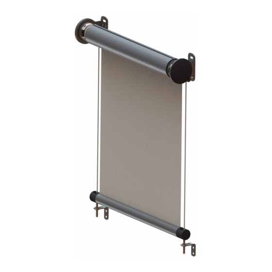
The SCREEN LITE roller blinds can be placed into an opening or in front of it, and attached to the ceiling or wall.
The screen roller blind width and height shall be measured as follows:
W ...... (width)
a) attachment into an opening:
Measure the actual opening width in three points, indicate the lowest
b) attachment in front of an opening:
As a rule, indicate the width of the opening which is to be shaded in the
Dimensions outside the stipulated limits must be consulted with the manufacturer.
H ...... (height)
Measure the overall height including the roller blind upper section and holder.
W
DIMENSIONS OUTSIDE THE STIPULATED LIMITS MUST ALSO BE CONSULTED WITH THE MANUFACTURER.
COLOUR:
Guide bars:
Standard version: RAL 9006 (light silver), RAL 9007 (dark silver), RAL 7016 (anthracite grey);
Other colours can be selected from the RAL colour chart.
Plastic components cannot be painted.
Instruction validity: as of 1 August 2013
Crank
MEASUREMENT AND ASSEMBLY MANUAL
dimension measured in the order
order
form.
form.
W
Crank
1
Advertisement
Table of Contents

Related Manuals for Isotra SCREEN LITE


Summary of Contents for Isotra SCREEN LITE
- Page 1 SCREEN LITE 1. MEASURE-TAKING The SCREEN LITE roller blinds can be placed into an opening or in front of it, and attached to the ceiling or wall. The screen roller blind width and height shall be measured as follows: W …… (width)
-
Page 2: Scope Of Use
Regular roller blind operation can be carried out by anybody. 3. TECHNICAL DESCRIPTION The SCREEN LITE system is available in a motorised or a cranked version. The design parts of the roller blind can be defined as follows: ... -
Page 3: General Safety Requirements
MEASUREMENT AND ASSEMBLY MANUAL remote controller or by an electrical control system interface. The suitable motor torque is selected according to the type of fabric and its relative weight. Cord guiding: Cord guides for a 19-strand cord, Ø 4 mm, made from stainless steel (AISI 316), together with a pressed-in tightening stainless steel end piece and AISI 316 stainless steel bracket for wall mounting. -
Page 4: Installation
MEASUREMENT AND ASSEMBLY MANUAL Take special precautions if using drills, where the component being drilled must be held by a hand. To attain higher output and lower drill bit break rate in portable drills, it is necessary to hold the tool while positioning your arm in a line with the tool axis. - Page 5 NOTE: Faulty installation can lead to accidents. Observe instructions for the proper roller blind installation to prevent the risk of separation of the roller blind from a wall or window. ISOTRA a. s. shall not be held responsible for defects caused by faulty installation.
- Page 6 6.3 INSTALLATION OF GUIDE BARS First, attach the box to the ceiling/wall, then install the guide bars. For model SCREEN LITE, only one type of guide bars is available – GC20. The bar is supplied with pre-drilled holes, as per order, from the front or from the side.
- Page 7 MEASUREMENT AND ASSEMBLY MANUAL Note: The places for the installation of the brackets must be selected before ordering the roller blinds, as this position determines the cord length. If brackets are installed upwards (b), leave at least 20 mm of space between the bracket and the floor or window sill. Attach the brackets to the wall using screws and components suitable for the type of structure onto which they are to be attached (metallic structure, cement, brick, etc.).
- Page 8 MEASUREMENT AND ASSEMBLY MANUAL 7. WIRING OF LITE SCREEN ROLLER BLIND Observe instructions indicated in the installation instructions for the motor supplied with this manual. All wiring must be made in accordance with valid IEC standards. Use impulse switches together with the control unit in all situations where there is more than one device to control the same roller blind.
- Page 9 MEASUREMENT AND ASSEMBLY MANUAL brown = phase/neutral conductor, yellow-green = ground. End switches for a motor installed in the winding drum are not pre-set, therefore the roller blind opening/closing positions are completely random. Motor end switches can be set up in various methods, according to the type and mark of the motor used.
-
Page 10: Operation
No special instructions have been stipulated for the disassembly or disposal of the roller blind. However, ISOTRA seeks to eliminate, if practicable, the use of such materials so that all parts of the roller blind conform to the requirements of said Directive. -
Page 11: Maintenance
MEASUREMENT AND ASSEMBLY MANUAL of replacement of the roller blind, it is possible to send the used roller blind to ISOTRA for disposal after a new roller blind has been ordered. 10. MAINTENANCE It is recommended to carry out regular maintenance of the roller blind every two years. No maintenance activities are... - Page 12 IMPORTANT: Do not disassemble the motor, otherwise the loss of guarantee shall arise. In case of any discrepancy in operation the user should contact the dealer or directly the manufacturer, ISOTRA a. s. Any and all maintenance must be carried out solely by qualified personnel. If the fabric or motor replacement is necessary, follow instructions given in the installation manual.
Need help?
Do you have a question about the SCREEN LITE and is the answer not in the manual?
Questions and answers