Isotra CETTA 50 Technical Manual
Exterior blinds
Hide thumbs
Also See for CETTA 50:
- Technical manual (158 pages) ,
- Control and maintenance manual (7 pages)
Table of Contents
Advertisement
Quick Links
Advertisement
Table of Contents

Related Manuals for Isotra CETTA 50


Summary of Contents for Isotra CETTA 50
- Page 1 TECHNICAL MANUAL EXTERIOR BLINDS...
- Page 2 Fiche technique du produit A mark symbolising long tradition, inestimable investment into development, the use of quality materials, state-of the-art technologies, reliable work from hundreds of employees and numerous other parameters, constituting one entity – the fi nal product of ISOTRA.
- Page 3 EXTERIOR BLINDS EXTERIOR BLINDS CE Product Marking All exterior blinds of ISOTRA a.s. comply with the standard ČSN EN 13659+A1:2009 European Marking of CE Compliance – marking on products ISOTRA a.s. Bílovecká 2411/1, 746 01 Opava Czech Republic Company Registration No.: 47679191...
-
Page 4: Table Of Contents
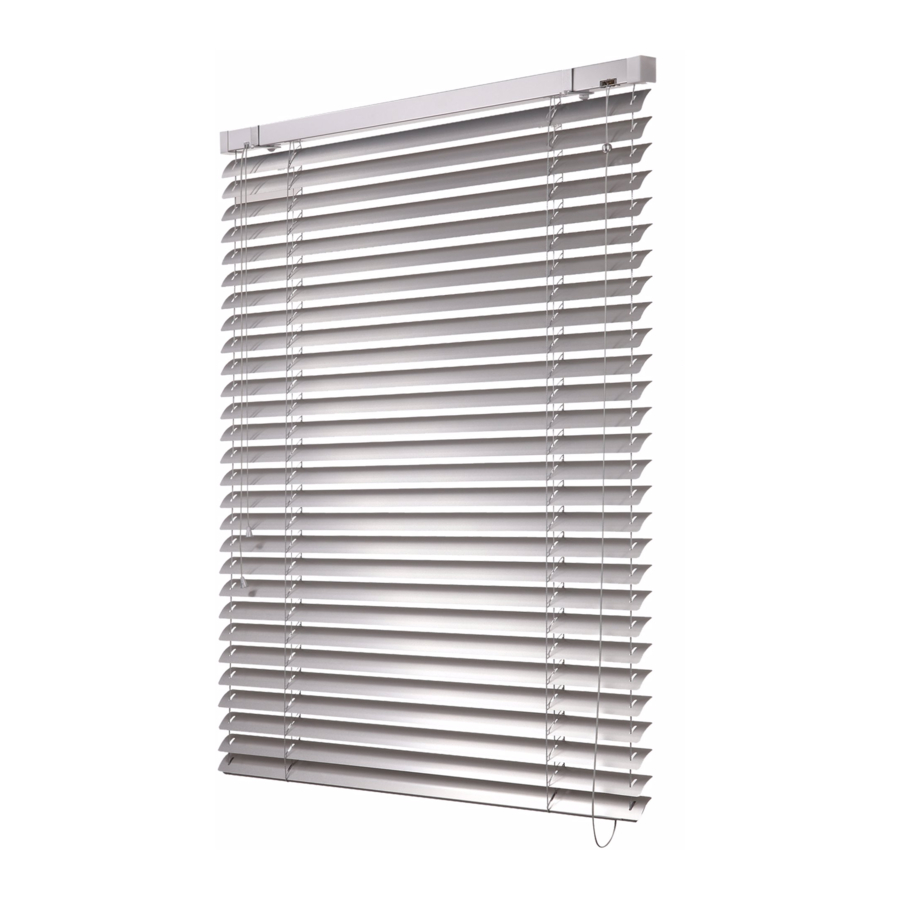
Zetta 90 Note: For Cetta 50 (motor), the coiling height will change by +40 mm. For Cetta 65, 80, 80-Flexi and Zetta 70 a 90 (motor), the coiling height will change by +20 mm. The coiling heights are approximate values which can deviate positively or negatively for technical reasons. - Page 5 EXTERIOR BLINDS Cetta 50 Suitable for shading small areas Optional assembly in interior Electrical control option ...
- Page 6 Cetta 50 Basic Product Specifi cation Slat bracket Metal ladder Ring for hexagonal End stop 35 mm connector metal wire 40 x 40 Slat bracket Side cover for head rail Head rail carrying bracket 50 mm *Head rail Bearing 40x40 Clamping screw –...
-
Page 7: Cetta 65
EXTERIOR BLINDS Cetta 65 Bottom rail made of extruded aluminum Higher slat rigidity Electrical control option ... - Page 8 According to current grey Basic design – grey grey galvanized steel plate anodized aluminum ISOTRA a.s. scheme anodized natural (Al profi l) Varnished in RAL Other RAL colors sprayed colors Other RAL colors sprayed We do not make atypical designs.
-
Page 9: Cetta 80
EXTERIOR BLINDS Cetta 80 Bottom rail made of extruded aluminum DUO system – double slat tilting Higher slat rigidity Electrical control option ... -
Page 10: Cetta 80
Standard: Standard: According to grey Standard: grey grey galvanized steel plate anodized aluminum current ISOTRA a.s. anodized natural (Al profi l) scheme Other RAL colors Other RAL colors Other RAL colors sprayed sprayed sprayed We do not make atypical designs. -
Page 11: Cetta 80 - Slim
EXTERIOR BLINDS Cetta 80 - Slim Low packet height Specific assembling of slats (side alternating overlap of adjacent slats) - Page 12 Standard: Standard: According to grey Standard: grey grey galvanized steel plate anodized aluminum current ISOTRA a.s. anodized natural (Al profi l) scheme Other RAL colors Other RAL colors Other RAL colors sprayed sprayed sprayed We do not make atypical designs.
-
Page 13: Cetta 80 Flexi
EXTERIOR BLINDS Cetta 80 - Flexi Bottom rail made of extruded aluminum DUO system – double slat tilting Lower blind coiling height Electrical control option ... - Page 14 Standard: Standard: According to grey Standard: grey grey galvanized steel plate anodized aluminum current ISOTRA a.s. anodized natural (Al profi l) scheme Other RAL colors Other RAL colors Other RAL colors sprayed sprayed sprayed We do not make atypical designs.
- Page 15 EXTERIOR BLINDS Setta 65 Elegant slat shape „S“ Bottom rail made of extruded aluminium Electrical control option Rubber pressed in along the entire slat width ensure lower ...
- Page 16 Color Standard: Standard: According to current Standard: grey grey galvanized steel plate anodized aluminum ISOTRA a.s. scheme anodized natural (Al profi l) Other RAL colors Other RAL colors Other RAL colors sprayed sprayed sprayed We do not make atypical designs.
- Page 17 EXTERIOR BLINDS Setta 90 Elegant slat shape „S“ Bottom rail made of extruded aluminium Electrical control option Rubber pressed in along the entire slat width ensure lower ...
- Page 18 Color Standard: Standard: According to current Standard: grey grey galvanized steel plate anodized aluminum ISOTRA a.s. scheme anodized natural (Al profi l) Other RAL colors Other RAL colors Other RAL colors sprayed sprayed sprayed We do not make atypical designs.
-
Page 19: Zetta 70
EXTERIOR BLINDS Zetta 70 High degree of shading Thermo-regulating and protecting effect Outside noise level reduction Bottom rail made of extruded aluminum Electrical control option Rubber pressed in along the entire slat width ... - Page 20 Color Standard: Standard: According to current Standard: grey grey galvanized steel plate anodized aluminum ISOTRA a.s. scheme anodized natural (Al profi l) Other RAL colors Other RAL colors Other RAL colors sprayed sprayed sprayed We do not make atypical designs.
- Page 21 EXTERIOR BLINDS Zetta 90 High degree of shading Thermo-regulating and protecting effect Outside noise level reduction Bottom rail made of extruded aluminum Electrical control option Rubber pressed in along the entire slat width ...
-
Page 22: Zetta 90
Color Standard: Standard: According to current Standard: grey grey galvanized steel plate anodized aluminum ISOTRA a.s. scheme anodized natural (Al profi l) Other RAL colors Other RAL colors Other RAL colors sprayed sprayed sprayed We do not make atypical designs. - Page 23 EXTERIOR BLINDS DUO System System with double slat tilting Blind divided into fully opened part and fully closed part Suitable for conference, training and work rooms ...
- Page 24 Alternative Designs DUO System (double slat tilting) Applies to the handle / motor control: Cetta 65, Cetta 80, Cetta 80-Flexi Upper blind part or lower blind part closed is available. It is impossible to fully open all slats at the same time. Diff erent slat tilting is achieved by the ladder shortened on one side.
-
Page 25: Setta 65
EXTERIOR BLINDS Alternative Designs Self-supporting blind, uprolling outside the channel Technical Specifi cation Cut of head rail Cut of guiding channel The maximum height of blind, which the box of 210 mm is suitable for. Blind Type Height of blind (mm) Cetta 65 1900 Cetta 80... - Page 26 Alternative Designs Self-supporting blind, uprolling outside the channel The sefl -supporting blind is suitable for smaller spaces. Measurement 31 without insect screen 59 with insect screen...
-
Page 27: Zetta 90
EXTERIOR BLINDS Alternative Designs Façade Blinds Front covers based on blind height (mm) Cetta 80 Zetta 90 Cassette 240 < 1750 < 3700 Cassette 332 < 3700 < 3700 Cassette 392 < 4000 < 4000 Installation B Installation A Standard head rail holder... - Page 28 Head rail bracket mechanical (Fe) P 002/3 (6-002319) Front cover bracket...
- Page 29 EXTERIOR BLINDS Double-sided / single-sided guiding channel Holder of guiding channel (2-00798) Guiding channel attachment...
- Page 30 Installation A – guiding channels inside the cassette One cover plate for more blinds. The guiding channels are installed inside the cassette. The guiding rails are fi tted with a rubber gasket. Every other slat is fi tted with a guide. Installation B –...
- Page 31 EXTERIOR BLINDS Variations of BOXES Placing of guiding channels...
- Page 32 Alternative Designs Self-Supporting Exterior Blinds Installation on Façade Suitable for all exterior blinds types except Cetta 50. Maximum width for self-supporting blinds: 2.4 m. Areas exceeding this size require consulting with the manufacturer! Required components: • self-supporting guiding channel •...
- Page 33 EXTERIOR BLINDS Alternative Designs Lintel Exterior Blinds The bushings for the guiding channels can be recessed in an insulation sandwich. The Venetian blind guiding channels can also be fi xed to a window frame using attachments. Fitting of bushing of exterior blinds with recessed guiding channel – standard Installation X = šířka žaluzie X -blind width Fitting of Venetian blind guiding channel in reveal...
- Page 34 Fitting of window frame for exterior blind Installation The window frame can be fi xed to the rolling lintel in the upper part using metal attachments and dowels. Distance between the outside brick molding of lintel and outside part of window frame is 220 mm. Standard Dimensions Minimum Width (mm) Maximum Width (mm)
- Page 35 EXTERIOR BLINDS Control The bearing HELUZ roller blind lintel can be fi tted either with manual or electric control. If the customer decides for the manual control using a handle, it is necessary to keep the lintel seating of 200, rather 250 mm, if possible, on the control side.
- Page 36 Cetta 65, Cetta 80, Cetta 80-Felxi, Zetta 70, Zetta 90 and Setta 90 Exterior blinds can be connected (not Cetta 50). It is also possible to con- nected blinds in the HELUZ lintel.
- Page 37 EXTERIOR BLINDS Alternative Designs Atypical Designs of Exterior Blinds All atypical designs can be controled by motor or handle limited by specifi ed angle. Blinds impossible to pull up. Blinds impossible to pull up. Blinds impossible to pull up. Blinds impossible to pull up. Blinds impossible to pull up.
- Page 38 Accessories Front Cover Typees T1 (2-00316) T2 (2-00317) T3 (2-00318) T4 (2-00319) T2b (2-00652) T3b (2-00653) T4b (2-00654) T2r (2-00655) T3r (2-00656) T4r (2-00657) T2s (2-00658) T3s (2-00659) T4s (2-00660) T1u (2-00661) T2u (2-00662) T3u (2-00663) T4u (2-00664) T1c (2-00665) T4c (2-00666)
- Page 39 EXTERIOR BLINDS Number of Exterior Blind Holders Based on Width (mm) Blind Width (mm) Pcs. to 1599 from 1600 to 2399 from 2400 to 3199 from 3200 to 4000 For arrangement of holders, consider the following: • maximum distance between two holders •...
- Page 40 Holders for Basic Front Cover Types TYPE 1 – 4 Fron cover T1 (2-00316) Front cover T2 (2-00317) Front cover T3 (2-00318) Front cover T4 (2-00319)
- Page 41 EXTERIOR BLINDS Side hanger for C50 Ceiling hanger for C50 P 512/5 (2-00651) P 512/4 (2-00793) (for head rail 40 x 40) (for head rail 40 x 40) Fixed hanger for C50 Fixed hanger for C50 with front cover P 512 (2-00057) P 513 (6-001244) (for head rail 40 x 40) (for head rail 40 x 40)
- Page 42 Head rail hanger Fe Head rail hanger Al Head rail hanger Fe – wire P 002 (2-00038) P 002/1 (2-00160) 2-00685 (for head rail 56 x 58) (for head rail 58 x 60) (for head reail 56 x 58) Head rail hanger Fe Click Fixed hanger (inner hanger Fe) 132 mm P 002/3 (6-002319) P 010 (2-00353)
- Page 43 EXTERIOR BLINDS Fixed hanger (inner hanger Al) 132 mm Fixed hanger (inner hanger Fe Click) 132 mm P 011 (2-00384) P 009 (2-00403) (for head rail 58 x 60) (for head rail 56 x 58) Adjustable hanger (inner hanger Fe) 103 - 160 mm Adjustable hanger (inner hanger Al) 103 - 160 mm P 010/1 (2-00354) P 011/1 (2-00373)
- Page 44 Adjustable hanger (inner hanger Fe Click) 107 - 164 mm Adjustable hanger (inner hanger Fe) 160 - 220 mm P 009/1 (2-00404) P 010/2 (2-00355) (for head rail 56 x 58) (for head rail 56 x 58) Adjustable hanger (inner hanger Al) 160 - 220 mm Adjustable hanger (inner hanger Fe Click) 160 - 220 mm P 011/2 (2-00374) P 009/2 (2-00405)
- Page 45 EXTERIOR BLINDS Atypical Holders for Front Covers P008_KBT1 – 11 (individual lead times) P008_KBT 1 (6-010604-0001) Front cover T2 (2-00317) (for head rail 40 x 40) P008_ KBT 2 (6-010604-0002) (for head rail 56 x 58) Front cover T3 (2-00318) P008_ KBT 3 (6-010604-0003) (for head rail 56 x 58)
- Page 46 P008_ KBT 4 (6-010604-0004) Front cover T3s (2-00659) (for head rail 56 x 58) P008_ KBT 5 (6-010604-0005) Front cover T3r (2-00656) (for head rail 56 x 58) Front cover T3b (2-00653)
- Page 47 EXTERIOR BLINDS P008_ KBT 7 (6-010604-0007) Front cover T1c (2-00665) (for head rail 56 x 58) P008_ KBT 8 (6-010604-0008) Front cover T4c (2-00666) (for head rail 56 x 58) P008_ KBT 9 (6-010604-0009) Front cover T4s (2-00660) (for head rail 56 x 58)
- Page 48 P008_ KBT 10 (6-010604-0010) Front cover T4b (2-00654) (for head rail 56 x 58) Holders for Applications under Plastering Front cover T3u (2-00663) P008_ KBT 6 (6-010604-0006) Front cover T2u (2-00662) (for head rail 56 x 58) P008_ KBT 11 (6-010604-0011) (for head rail 56 x 58) Front cover T4u (2-00664)
- Page 49 EXTERIOR BLINDS Guidance - Guiding Channel Guiding channels applies to: Cetta 50, Cetta 65, Cetta 80, Cetta 80-Flexi, Zetta 70, Zetta 90, Setta 65, Setta 90 P 018/2 (3-00381) P 018/1 (3-01475) P 016/1 (3-01476) P 017/1 (3-00379) P 018/4 (3-01794)
- Page 50 Single Guiding Channel P 018/1 (3-01475) Single Guiding Channel P 018/1 (3-01475) for installation in lining (with use of bracket) for installation on frame and façade (with use of bracket) Single Guiding Channel P 018/2 (3-00381) Single Guiding Channel P 017/1 (3-00379) for installation in lining (without use of bracket) for installation on frame and façade (with use of bracket)
- Page 51 EXTERIOR BLINDS Self-Supporting Guiding Channel P 016/1 (3-01476) Self-Supporting Guiding Channel P 016/1 (3-01476) for installation in lining (without use of ejector) for installation on frame and façade (with use of ejector) Single-Sided Round Channel P 018/4 (3-01794) Double-Sided Round Guiding Channel P 017/5 (3-01795) for installation on frame and façade (with use of ejector) for installation on frame and façade (with use of ejector) 37,6...
- Page 52 P018/31 P018/31 (3-01419) Guiding Channel under Plastering P018/31 (3-01419) + P018/3 (3-01418) for installation under plastering P018/3 P018/3 (3-01418) Guiding Channel under Plastering P018/51 (3-01968, Al) Insert in Channel under Plastering P018/5 (3-01782, PVC) for installation under plastering Available from 08-2011 Guiding Channel Holders Guiding channel holder, P021 (2-00050) Guiding for Guiding channel holder, P021 (2-00050) for guiding...
- Page 53 EXTERIOR BLINDS Telescopic guiding channel holder, Telescopic guiding channel holder, P021/3 (6-004497-1700) for guiding channel P018/1, P021/4 (6-004497-2950) for guiding channel P018/1, P 018/4 and P 017/5 P 018/4 and P 017/5 Telescopic guiding channel holder STS, 50 – 70 mm Telescopic guiding channel holder, STS, 75 –...
- Page 54 Guiding Channel Holder Type Distance between Guiding Rail and Window Frame (mm) Guiding channel holder, 50 - 70 mm P 021 43 - 62 Guiding channel holder, 70 - 100 mm P 021/1 63 - 92 Guiding channel holder, 100 - 145 mm P 021/2 93 - 145 Telescopic guiding channel holder, 104 - 170 mm P 021/3 105 - 170...
- Page 55 EXTERIOR BLINDS Guide types for Venetian blinds with guidance using guiding channels Metal guides Plastic guides “C” “C” “Z” “Z” “C,S,Z”...
- Page 56 Distance between wire guide and window frame There are 3 diff erent distances between wire and window frame for Cetta 50. This distance is given by the spacing of apertures in the corner guide. A corner guide with optionally regulated distance between wire and window frame is designated for Cetta 65 and Cetta 80.
- Page 57 DETAIL B DETAIL B Handle hexagonal 45° and 90° (P 150/1, 2-00298) Handle square 90° with cardan (P 150/3, 2-00300) (Cetta 50) (Cetta 65, Setta 65, Cetta 80, Cetta 80-Flexi, Zetta 70, Zetta 90, Setta 90) chrome chrome chrome Handle square 90°...
- Page 58 P045 (6-001179) P045/1 (6-001180) Gearing with hexagonal aperture Gearing with hexagonal aperture, extended (STS) P045/2 (6-003417) P045/4 (6-008115) Gearing with hexagonal aperture for handle control Gearing for cord control (Cetta 35, Cetta 50) (Cetta 35, Cetta 50) P228 (2-00132) P227 (2-00133)
- Page 59 EXTERIOR BLINDS Gearing Shift Scheme The gearing position (possible shift) in the head rail depends on the specifi c mounting of frame window, reveal. The gearing axis is the dis- tance of the gearing center axis from the outer edge of guiding channel, or outer edge of slat in the case of the steel wire guidance. Safety Instructions: •...
- Page 60 Motor control Motor Wiring Diagram RTS Motor Wiring Diagram 1 - Blue 2 - Black 3 - Brown L1 : phase 1 - neutral wire (N) PE - Yellow-green N : neutral 2 - phase wire (L) PE : ground 3 - not connected 4 - ground wire (PE) Parameter...
- Page 61 EXTERIOR BLINDS Setting Adjustment When setting the end position, the motor speed is set. If the end position is not set correctly, or if the Venetian blind behavior, and thus the bottom rail end position, has changed due to ambient eff ects and increased friction, the required end position must be re-set according to the above-described procedure.
- Page 62 Measurement Measurement of the Standard Blind Both width and height is always to be measured in three points. The manufacturing dimension of the exterior blind is always the smallest mea- sured value. Always carry out measuring after the frame is fi tted in the construction aperture, event. window after the internal and external reveals are completed, including parapets.
- Page 63 EXTERIOR BLINDS Standard Exterior Blind Assembly Procedure The assembly may only be performed by a qualifi ed professional employee! Construction preparedness for the assembly: · fi nished reveal, coloured façade, fi nished outside parapets INSPECTION: · Before assembly we recommend inspecting all the parts after the delivery of the goods to prevent any problems.
- Page 65 EXTERIOR BLINDS...
- Page 66 Basic types of assembly Assembly of the blind into the created pocket Assembly of the blind into the reveal on the window frame (ceiling/wall) (ceiling/wall) There are two alternatives for all three basic assembly types: Assembly of the blind into the reveal on the expansion frame a) Cover box (ceiling/wall)
- Page 67 EXTERIOR BLINDS ZETTA 70, ZETTA 90 EXTERIOR BLIND DIAGRAM VERTICAL SECTION HANDLE CONTROL Slat guidance in guiding channel...
- Page 68 ZETTA 70, ZETTA 90 EXTERIOR BLIND DIAGRAM VERTICAL SECTION HANDLE CONTROL Slat guidance in guiding channel – with extension...
- Page 69 EXTERIOR BLINDS ZETTA 70, ZETTA 90 EXTERIOR BLIND DIAGRAM HORIZONTAL SECTION HANDLE CONTROL...
- Page 70 ZETTA 70, ZETTA 90 EXTERIOR BLIND DIAGRAM HORIZONTAL SECTION HANDLE CONTROL Slat guidance in double guiding channel...
- Page 71 EXTERIOR BLINDS ZETTA 70,90 EXTERIOR BLIND DIAGRAM HORIZONTAL SECTION MOTOR CONTROL...
- Page 72 CETTA 80, CETTA 65 EXTERIOR BLIND DIAGRAM VERTICAL SECTION HANDLE CONTROL Slat guidance in guiding channel.
- Page 73 EXTERIOR BLINDS CETTA 80, CETTA 65 EXTERIOR BLIND DIAGRAM VERTICAL SECTION HANDLE CONTROL Slat guidance using a steel wire...
- Page 74 SETTA 65,90 EXTERIOR BLIND DIAGRAM VERTICAL SECTION HANDLE CONTROL Slat guidance in guiding channels (65)
- Page 75 EXTERIOR BLINDS SETTA 65,90 EXTERIOR BLIND DIAGRAM VERTICAL SECTION MOTOR CONTROL Slat guidance in guiding channels...
- Page 76 SETTA 65,90 EXTERIOR BLIND DIAGRAM HORIZONTAL SECTION MOTOR CONTROL...
- Page 77 EXTERIOR BLINDS Note...
- Page 78 Note...
- Page 79 EXTERIOR BLINDS...
- Page 80 ISOTRA a.s. ISOTRA Partner Bílovecká 2411/1, 746 01 Opava Czech Republic Tel.: +420 553 685 111 Fax: +420 553 685 110 E-mail: isotra@isotra.cz www.isotra.cz Released: 12/2013 … … privacy.
Need help?
Do you have a question about the CETTA 50 and is the answer not in the manual?
Questions and answers