Advertisement
Quick Links
INSTRUCTIONS FOR MEASURE-TAKING AND INSTALLATION
SELF-SUPPORTING BLIND, UPROLLING OUTSIDE THE CHANNEL
1. MEASURE-TAKING
Measure-taking applies to width (W) and height (H) of the opening.
The blind width should be measured in three points – atop, in the middle and at the bottom.
For manufacture and order, the lowest dimension measured is indicated.
(1) - electrical cable
W
W
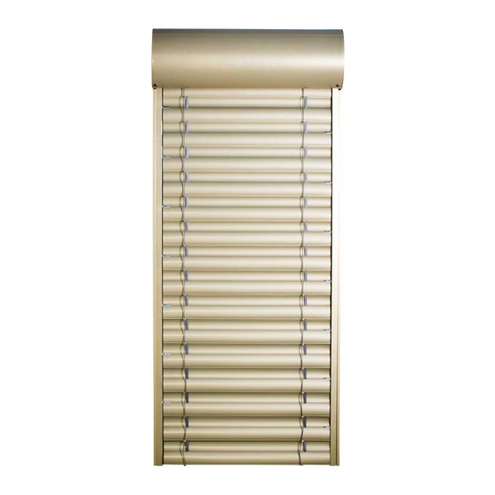
2. INDIVIDUAL PARTS
(2) - self-supporting box
(3) - guide bars
(4) - slat packet
Instruction validity: as of 1 August 2013
Advertisement

Related Manuals for Isotra SELF-SUPPORTING BLIND, UPROLLING OUTSIDE THE CHANNE


Summary of Contents for Isotra SELF-SUPPORTING BLIND, UPROLLING OUTSIDE THE CHANNE
- Page 1 INSTRUCTIONS FOR MEASURE-TAKING AND INSTALLATION SELF-SUPPORTING BLIND, UPROLLING OUTSIDE THE CHANNEL 1. MEASURE-TAKING Measure-taking applies to width (W) and height (H) of the opening. The blind width should be measured in three points – atop, in the middle and at the bottom. For manufacture and order, the lowest dimension measured is indicated.
- Page 2 INSTRUCTIONS FOR MEASURE-TAKING AND INSTALLATION 3. WIRING Versions of the recommended positioning of the electrical cable (5) - rear outlet (6) - side outlet 3.1 CABLE INNER LEAD Instruction validity: as of 1 August 2013...
- Page 3 INSTRUCTIONS FOR MEASURE-TAKING AND INSTALLATION 4. ATTACHMENT OF THE SELF-SUPPORTING FRAME IN THE REVEAL Slide the basic guide bars to the blind box; Place and secure the box in the reveal; (7) - box attachment. 5. SCREEN ADJUSTMENT ...
- Page 4 INSTRUCTIONS FOR MEASURE-TAKING AND INSTALLATION 6. SLAT MOUNTING Slide the slat packet (4) into the blind suspensions (10). 7. SECURING THE PACKET Turn the spring to lock the system against release; (11) - lock spring. Instruction validity: as of 1 August 2013...
- Page 5 INSTRUCTIONS FOR MEASURE-TAKING AND INSTALLATION 7.1 LOCKED PACKET Spring clicked in the slot. 8. ELECTRICAL INSTALLATION – RECOMMENDED METHOD Couple the connectors (13), lead the cable on the upper side of the channel front area; Secure the cable using clamping bands (12). Instruction validity: as of 1 August 2013...
- Page 6 INSTRUCTIONS FOR MEASURE-TAKING AND INSTALLATION 9. FIXING THE BLIND GUIDE BARS Slide the blind guide bar (14) into the guide pieces (15). 10. LOCKING THE GUIDE BARS Use screw (16) to attach the blind guide bar to the basic guide bar. 10.1 REPEAT THE SAME METHOD FOR THE OTHER SIDE OF THE BLIND Instruction validity: as of 1 August 2013...
- Page 7 INSTRUCTIONS FOR MEASURE-TAKING AND INSTALLATION 11. FIXING THE REVISION COVER (17) - revision cover. 11.1 ATTACHMENT OF THE REVISION COVER Use screw (18) with a plastic washer. Instruction validity: as of 1 August 2013...
- Page 8 INSTRUCTIONS FOR MEASURE-TAKING AND INSTALLATION 11.2 FIXING A SCREW CAP Fix cap (19) to the screw head. 12. FUNCTIONALITY CHECK Instruction validity: as of 1 August 2013...
- Page 9 INSTRUCTIONS FOR MEASURE-TAKING AND INSTALLATION CHECK: Prior to assembly, we recommend checking the components upon delivery, thus preventing eventual problems. Please inform the manufacturer of any deficiencies and/or notes regarding the assembly or the blind as such. ASSEMBLY TOOLS: 1.
Need help?
Do you have a question about the SELF-SUPPORTING BLIND, UPROLLING OUTSIDE THE CHANNE and is the answer not in the manual?
Questions and answers