Table of Contents
Advertisement
Quick Links
Download this manual
See also:
Operator's Manual
Advertisement
Table of Contents

Subscribe to Our Youtube Channel
Related Manuals for Trumpf TruTool N 700


Summary of Contents for Trumpf TruTool N 700
- Page 1 Operator's manual TruTool N 700 (1A2) english...
-
Page 2: Table Of Contents
Setting work ...............8 Choosing a dieen..............8 Selecting a punch ..............10 Checking penetration depth of the punch......11 Operation ................12 Working with TruTool N 700 ..........12 Changing the cutting direction ...........13 Nibbling with templates............13 Making interior cutouts............13 Maintenance ..............14 Changing the tool...............15 Changing the punch .............15... -
Page 3: Safety
Safety General safety information Before starting-up the machine, read the operator's manual and the safety information (order no. 0373678) in their entirety and carefully follow the instructions given. Comply with the safety regulations in accordance with DIN VDE, CEE, AFNOR as well as any other regulations valid in the individual countries. - Page 4 Always position the compressed air hose leading away from Caution the machine, at back of the machine. Do not pull the cable over sharp edges. Have servicing and inspections of hand-held compressed air tools carried out by a qualified technician. Only use original TRUMPF accessories. Safety E211EN_03.DOC...
-
Page 5: Description
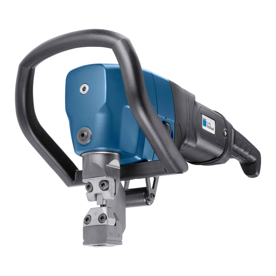
38 Handle (can be mounted in 2 Punch guide 36 Clamping screw for the die different positions) Die carrier carrier 345 On/Off switch 37 Cap screw (2 pieces) for Punch fastening the handle Nibbler TruTool N 700 Fig. 9545 Description E211EN_03.DOC... -
Page 6: Intended Use
Only use the machine for the work and materials described under "Intended use". Warning The TRUMPF Nibbler N 700 is a hand-held device powered by compressed air used for the following applications: • Slitting plate-shaped workpieces made of a punchable material such as steel, aluminum, non-ferrous heavy metals and plastic. -
Page 7: Technical Data
Technical data Other countries Value Value Max. material thickness: 7.0 mm 0.28 in / Ga • Steel 400 N/mm². 5.0 mm 0.20 in / Ga • Steel 600 N/mm². 3.5 mm 0.14 in / Ga • Steel 800 N/mm². 10.0 mm 0.40 in / Ga •... -
Page 8: Setting Work
Setting work Choosing a dieen One of 3 types of dies can be selected for the machining process according to material thickness, tensile strength and type of workpiece. Make sure that the clearance (X) is as small as possible so that the machine is well clamped and does not hammer. - Page 9 Use the die with the greatest available height Workpiece Punch guide Clearance between sheet surface Punch and punch guide Die clearance for punch guide Fig. 16811 Note The clearance (x) between the sheet surface and the punch must remain as small as possible. Does severe back-and-forth movement (hammering) occur during the cutting process? This is caused by using an unsuitable die, and can result in...
-
Page 10: Selecting A Punch
Selecting a punch There are 2 different punches for machining sheets with different tensile strengths: Components Punch Standard High-tensile Order no. 104589 104590 Aluminum 250 N/mm Mild steel 400 N/mm Stainless steel 600 N/mm² Stainless steel 800 N/mm² Table 5 Setting work E211EN_03.DOC... -
Page 11: Checking Penetration Depth Of The Punch
Checking penetration depth of the punch Die carrier 21 Eccentric shaft Punch 36 Clamping screw Penetration depth Penetration depth of the punch Fig. 9015 The penetration depth of the punch into the die should be 1 to 3 mm. 1. Rotate the eccentric shaft (21) until the punch (9) has reached its maximum penetration depth. -
Page 12: Operation
Operation Working with TruTool N 700 Risk of injury due to improper handling. Make sure the machine is always in a stable position when operating it. Warning Never touch the tool while the machine is running. Always operate the machine away from your body. -
Page 13: Changing The Cutting Direction
Release the lever (2). Switching off the TruTool N 700 The lever springs back to the initial position and the compressed air is interrupted. Changing the cutting direction In situations where space is limited, the tool can be mounted so it has a different cutting direction: •... -
Page 14: Maintenance
Maintenance Risk of injury due to uncontrolled machine movements. Remove the compressed air hose when changing tools and before performing any maintenance work on the machine. Warning Risk of injury due to repair work not being carried out properly. Machine does not work properly. Warning Repair work may only be carried out by a qualified technician. -
Page 15: Changing The Tool
Changing the tool If the punch and/or die are blunt or the type of operation changes, the tools must be reground or changed. Die carrier Screws for fastening the die and Punch punch guide 36 Clamping screw Punch guide Lubricating grease "S1" Wearing plate (order no. -
Page 16: Changing The Die And The Punch Guide
6. Insert the punch (9) by rotating it 7. Align the punch to 45°. 8. Install the die carrier (7). 9. Check the penetration depth of the punch. Changing the die and the punch guide 1. To replace the die and the punch guide, unscrew the fixing screws (4). -
Page 17: Dies
• Lightly apply fine-grained oil stone to the cutting edge. • Observe a minimum length of 89 mm Shorter punches must be replaced (risk of collision). Dies Dies can not be resharpened. Checking/replacing the wearing plate Elevation Depression Fig. 9468 Wearing plate The wearing plate protects the die carrier against excessive wear (order no. -
Page 18: Supplying With Power And Guaranteeing Lubrication
Supplying with power and guaranteeing lubrication Damage to property due to improper handling. Failure of the compressed air motor. Do not exceed the maximum operating pressure. Caution Lubricate the compressed air motor regularly. Alternatively, install an oil mist lubrication device into the compressed air line. - Page 19 Hold a piece of paper in front of the exhaust air vent in the Checking the oil supply motor housing while the machine is running. The oil supply is sufficient when oil spots appear. Lubricating the compressed- air motor max. 15mm 312 Grease nipple for lubricating the Machine middle axis...
-
Page 20: Replacing Fins
Lubricating the speed limiter Lubricate the speed limiter (324) and ball bearings with lubricating grease during the regular maintenance of the and ball bearings machine (see replacement parts list). Note Handle the speed limiter (324) especially carefully, as damage can lead to excessive rotation speed. -
Page 21: Original Accessories And Irreparable Parts
Original accessories and irreparable parts TruTool N 700 Supplied Irreparable Options Order no. original parts accessories Block tools (punch and die, installed) Quick-release coupling (part on the machine 114094 side) Quick-release coupling (part on the hose side) 114095 Handle 103555... - Page 22 Desired delivery type (e.g. air mail, courier, express mail, – ordinary freight, parcel post). 4. Send the order to the TRUMPF representative office. Refer to the address list at the end of the document for TRUMPF service addresses. Original accessories and irreparable parts...
Need help?
Do you have a question about the TruTool N 700 and is the answer not in the manual?
Questions and answers