
Related Manuals for Festo Checkbox Series


Summary of Contents for Festo Checkbox Series
- Page 1 The Checkbox family Manual Checkbox Identbox Countbox Sortbox Manual 526 373 [649 320] en 0103c...
- Page 3 ....... . . 526 373 E (Festo AG & Co., D-73726 Esslingen, Federal Republic of Germany, 2001) Internet: http://www.festo.com...
- Page 4 Contents and general instructions Festo P.BE-Checkbox-EN en 0103c...
-
Page 5: Table Of Contents
..........2-16 Festo P.BE-Checkbox-EN en 0103c... - Page 6 ......6.1.5 Set counter function (Countbox, Sortbox) ......Festo P.BE-Checkbox-EN en 0103c...
- Page 7 ............Festo P.BE-Checkbox-EN en 0103c...
- Page 8 Contents and general instructions Festo P.BE-Checkbox-EN en 0103c...
-
Page 9: Designated Use
– The features of the conveyed part which determine the orientation or quality must be recognizable and distin- guishable for the Checkbox. – It must be possible to integrate the conveyor unit in the material flow. Festo P.BE-Checkbox-EN en 0103c... -
Page 10: Target Group
This manual is intended exclusively for technicians trained in control and automation technology, who have experience in installing and commissioning electrical systems. Service Please consult your local Festo service centre if you have any technical problems. Scope of delivery Checkbox Conveyor unit –... - Page 11 Wired at the factory: Internal power supply of the I/O module. Operation without buffer zone sensors i.e. sensor inputs 3...6 wired with reference voltage (Sortbox). A summary of additional accessories available can be found in chapter A.6. Festo P.BE-Checkbox-EN en 0103c...
-
Page 12: Important User Instructions
This means that failure to observe this instruction may result in damage to property. The following pictogram marks passages in the text which describe activities with electrostatically sensitive compo- nents. Electrostatically sensitive components may be damaged if they are not handled correctly. Festo P.BE-Checkbox-EN en 0103c... - Page 13 Text markings The bullet indicates activities which may be carried out in any order. 1. Figures indicate activities which must be carried out in the sequence shown from top to bottom. – Hyphens indicate general activities. Festo P.BE-Checkbox-EN en 0103c...
- Page 14 Input pin 1 Output pin 2 O/2 – Plug connectors are shown viewed towards the device. This representation corresponds to the view (from the cable side) of the connections to be wired. Festo P.BE-Checkbox-EN en 0103c...
-
Page 15: Notes On This Manual
The pre-setting of the Checkbox can be modified if required with the software packages CheckKon (function “Modify sys- tem”) or CheckOpti available as options. Further information on the software packages can be found in the manuals listed under “Documentation on the Checkbox family.” XIII Festo P.BE-Checkbox-EN en 0103c... -
Page 16: Documentation On The Checkbox Family
Orientation 1 is the preferred orientation (nominal orientation). Parts type Conveyed part defined by the teach data of the sample parts. Sample parts Parts shown during the teach procedure. Festo P.BE-Checkbox-EN en 0103c... - Page 17 Checkbox and classified according to their features with regard to orientation and observance of tolerances. This is also referred to as ”Testing parts”. Tolerance Factor in percent related to the average values which has an effect on the min./max. limits of all the features. Festo P.BE-Checkbox-EN en 0103c...
- Page 18 Contents and general instructions Festo P.BE-Checkbox-EN en 0103c...
-
Page 19: System Summary
System summary Chapter 1 Festo P.BE-Checkbox-EN en 0103c... - Page 20 ........... . 1-10 Festo P.BE-Checkbox-EN en 0103c...
-
Page 21: The Checkbox Family
Countbox Functions as with Identbox plus: Counting of good parts with preselectable nominal amount Sortbox Functions as with Countbox plus: simultaneous sorting and commissioning of sev- eral different conveyed parts Festo P.BE-Checkbox-EN en 0103c... -
Page 22: Software Packages For The Checkbox
– Display, evaluation and printout of statistical data of the tested parts. The software packages have been developed specially for the Checkbox family products and can be used with all the de- vices in the Checkbox family. Festo P.BE-Checkbox-EN en 0103c... -
Page 23: Scope Of Functions Of The Checkbox
– Sorting into different buffer zones. Commissioning Putting together a parts assortment – Transport of defined amounts of components (1...10 million) by specifying a nominal number of good parts. – Nominal number freely selectable for each parts type. Festo P.BE-Checkbox-EN en 0103c... -
Page 24: Components Of The Checkbox
– the belt speed, the direction of movement of the belt – the number of reject positions. Further information on the various designs of conveyor unit can be found in the chapter A.5 “Technical specifications”. Festo P.BE-Checkbox-EN en 0103c... -
Page 25: Method Of Operation Of The Checkbox
LED lighting. The camera registers each conveyed part in contour images. From the contours the system ascertains part-specific features such as the length, breadth and sur- face. Festo P.BE-Checkbox-EN en 0103c... - Page 26 Faulty or foreign parts are rejected. The conveyor unit is fitted with at least two compressed air nozzles which blow conveyed parts down from the belt at certain positions. The remaining conveyed parts leave the belt at the end. Festo P.BE-Checkbox-EN en 0103c...
- Page 27 The number and arrangement of the delivery positions can vary depending on the Checkbox version. The assignment of the positions can be modified with the CheckKon software (function “Modify system”). Festo P.BE-Checkbox-EN en 0103c...
-
Page 28: Buffer Zone
With the CheckKon software you can modify the following settings of the buffer zones. – Switching logic (buffer zone sensor type = normally open/ closed). – Signal delay (minimum sensor signal duration for status “Buffer zone empty” or “Buffer zone full”. 1-10 Festo P.BE-Checkbox-EN en 0103c... - Page 29 – the geometry of the conveyed parts – the maximum time delay beween the small parts conveyor being switched on again and the availability of the new conveyed parts – the length and speed of the conveyor belt 1-11 Festo P.BE-Checkbox-EN en 0103c...
- Page 30 – After a preset time, e.g. 30 s, the small parts conveyor will be switched off – The conveyor belt continues to run HIGH Sensor does not The small parts conveyor is switched on. at sensor 1 register any con- veyed part 1-12 Festo P.BE-Checkbox-EN en 0103c...
- Page 31 – After a preset time, e.g. 30 s, the small parts conveyor will be switched off – The conveyor belt continues to run HIGH Sensor does not The small parts conveyor is switched on. at sensor 1 register any con- veyed part 1-13 Festo P.BE-Checkbox-EN en 0103c...
- Page 32 – The conveyor belt continues to run. HIGH At least one The small parts conveyor is switched on. on at least one sensor does not sensor output register any con- veyed part 1-14 Festo P.BE-Checkbox-EN en 0103c...
-
Page 33: Fitting And Installation
Fitting and Installation Chapter 2 Festo P.BE-Checkbox-EN en 0103c... - Page 34 ..........2-16 Festo P.BE-Checkbox-EN en 0103c...
-
Page 35: Fitting The Modules
In this way you will achieve optimum test results and guar- antee a long service life of the devices. Space required Please observe the space required for mounting the Check- box. The dimensions of the Checkbox and weight specifica- tions can be found in chapter A5. Festo P.BE-Checkbox-EN en 0103c... - Page 36 Heron connector HV-50 connector as connector 4 x slotted head screw 2 x slotted head screw M6x40 DIN 912 Fastening the controller Fasten the controller with 4 M8 screws on the rear of the con- troller housing. Festo P.BE-Checkbox-EN en 0103c...
- Page 37 Controller X4 Conveyor unit with camera (hybrid cable) X5 Mains cable Diagnostic interface X1 Small parts conveyor X2 Buffer zone sensors X3 Fig. 2/1: Connections and interfaces of the controller Festo P.BE-Checkbox-EN en 0103c...
-
Page 38: Power Supply Connections Of The Controller
Adjustment by hand is not necessary. Warning Connect the Checkbox only when it is in faultless condition. Use only the original connecting cable. Controller X4 Conveyor unit with camera X5 Mains cable Fig. 2/2: Electrical connections of the controller Festo P.BE-Checkbox-EN en 0103c... -
Page 39: Pneumatic Connection
The compressed air supply for the rejecct valves must fulfil the following requirements: – supply: 4...6 bar overpressure – non-lubricated dried and filtered with filter 40 ìm. – Festo P.BE-Checkbox-EN en 0103c... - Page 40 Fig. 2/3: Connections of the conveyor unit Please note Use the Checkbox only with the compressed air tubing from Festo included in delivery: part no. 152 587 (@ 8 mm, 3 m long, quick coupling plug). Connect the Checkbox conveyor unit to the compressed air...
-
Page 41: Operation Without Buffer Zone Sensors
1...2 are then wired with the reference voltage. Make sure that the plug “Controller” is inserted at con- nection 1 (see 2.2.1 Supplying the I/O module). At the same time, sensor inputs 3...6 of the Sortbox are wired with the reference voltage. Festo P.BE-Checkbox-EN en 0103c... - Page 42 Sortbox Buffer zone sensor 6 Sensor inputs I/25 and I/26 are already connected internally to 24 V DC via the plug “Sensors”. The plug “Controller” wired at the factory bridges the connections “Buffer zone sensors 3...6”. 2-10 Festo P.BE-Checkbox-EN en 0103c...
-
Page 43: Operation With Buffer Zone Sensors
2. Loosen the screw terminals on the plug and remove the bridges fitted at the factory between the sensor inputs and the reference voltage. 3. Connect the buffer zone sensors to the non-assigned sensor inputs. 4. Screw the plug into the plug housing. 2-11 Festo P.BE-Checkbox-EN en 0103c... - Page 44 The sensor inputs are negative-switching (normally-closed). If 24 V DC is applied, the small parts conveyor will be switched on. As an option, direct connection with a Festo DUO cable is also pos- sible. Cable designation signal x (= I/1), signal x+1 (= I/2).
-
Page 45: Buffer Zone Sensors At The Connection "Controller
4. Connect unused sensor inputs with the 24 V DC reference voltage (HIGH). 5. Place the locking rings on the screws and tighten the plug on the plug housing. 6. Insert the plug into connection 1 (Fig. 2/4). 2-13 Festo P.BE-Checkbox-EN en 0103c... - Page 46 If you are using both sensor inputs at the connection “Controller”: S Remove the bridges fitted at the factory in the plug “Sensors”. S Then screw the plug “Sensors” into connection 2 (Fig. 2/4). Only in this way is the Checkbox ready to operate. 2-14 Festo P.BE-Checkbox-EN en 0103c...
-
Page 47: Controlling The Small Parts Conveyor
Contact loading 48 V / 100 mA On the connection “Controller” there is also an output (O/37) intended for controlling the small parts conveyor. However, this is not designed as a floating normally-open contact, but as a 24 V power output. 2-15 Festo P.BE-Checkbox-EN en 0103c... -
Page 48: Diagnostic Interface
Use an electrical isolation (optocoupler) between the PC and the Checkbox. If you have any technical problems, please consult your Festo Service. Further information on commissioning, optimizing and moni- toring the Checkbox via the PC interface can be found in the documentation for the software packages CheckOpti and CheckKon. - Page 49 The I/O module on the Checkbox Chapter 3 Festo P.BE-Checkbox-EN en 0103c...
- Page 50 ..........3-21 Festo P.BE-Checkbox-EN en 0103c...
-
Page 51: The I/O Module On The Checkbox
26, 7 Reference voltage GND, + 24 V DC 15, 16 Power supply Internal or external power supply for the I/O mod- 34, 35 ule is described in section 3.2 “Power supply for the I/O module”. Festo P.BE-Checkbox-EN en 0103c... - Page 52 If you use high resistance measuring devices for measur- ing the voltage at the outputs, a minimum loading of 1 mA will be required. In this way you can be sure that correct voltage values will be displayed. Festo P.BE-Checkbox-EN en 0103c...
-
Page 53: Internal Power Supply Of The I/O Module
Checkbox. Connector socket “Controller” on the Checkbox Internal power supply O/16 Internal GND O/35 Internal + 24 V DC I/15 External GND I/34 External + 24 V DC + 24 V DC Festo P.BE-Checkbox-EN en 0103c... - Page 54 2. Remove the bridge between pins 16 and 15 (GND). 3. Remove the bridge between pins 35 and 34 (+ 24 V DC). 4. Connect pin 15 with the earth/ground potential (0 V) of the external power supply. Festo P.BE-Checkbox-EN en 0103c...
- Page 55 O/7 and O/26. In the stop status this reference voltage is switched off. Title Function O/26 Reference voltage e.g. as reference potential for PLC Reference voltage e.g. as power supply for buffer zone + 24 V DC sensors Fuses 300 mA, self-resetting Festo P.BE-Checkbox-EN en 0103c...
-
Page 56: Connecting A Higher-Order Controller
O/11 Actuator 4 – Incorrectly orientated O/29 Actuator 5 parts/incorrect parts O/20 Actuator 6 type Actuator 7 – Bad/foreign parts Fault status 0: Warning Error messages O/22 Fault status 1: Error O/21 Fault status 2: Classification Festo P.BE-Checkbox-EN en 0103c... - Page 57 Counter reading check O/13 Preselected counter read- ing of all parts types reached I/10 Sorting program bit 0 External sorting program I/28 Sorting program bit 1 selection Sorting program bit 2 I/27 Sorting program bit 3 Festo P.BE-Checkbox-EN en 0103c...
-
Page 58: Start/Stop Mode
STOP button. – After a manual stop: With a change of signal LOW>HIGH (start signal) at I/33, the Checkbox can be switched on again after a manual stop. 3-10 Festo P.BE-Checkbox-EN en 0103c... - Page 59 Pin O/2 Checkbox mode 0 TEACH Pin I/33 Remote start Pin O/14 Checkbox mode 1 Pin O/2 Checkbox mode 0 SELECT Pin I/33 Remote start Pin O/14 Checkbox mode 1 Pin O/2 Checkbox mode 0 3-11 Festo P.BE-Checkbox-EN en 0103c...
- Page 60 Pulse-time diagram mode Operating status External stop signal from the controller after a manual start SELECT Pin I/33 Remote start Pin O/14 Checkbox mode 1 Pin O/2 Checkbox mode 0 (min. 3 s) Manual start 3-12 Festo P.BE-Checkbox-EN en 0103c...
-
Page 61: Counter Reading Check (Countbox, Sortbox)
Counter reading check Pin I/32 Start new counting cycle 100 ms < t < 500 ms Pin O/13 Preselected counter reading reached max. 600 ms pc = sc = start counting cycle pc = preselected counter status 3-13 Festo P.BE-Checkbox-EN en 0103c... -
Page 62: Displays At The Transfer Position
Actuator 3 The + 24 V DC signal is present when the O/30 good part passes the end of the system edge (guide rail of the conveyor unit). 3-14 Festo P.BE-Checkbox-EN en 0103c... - Page 63 If the Checkbox recognizes a test part as a bad or foreign part, pin O/1 (actuator 7) will be set from rest potential 0 V to + 24 V DC. 3-15 Festo P.BE-Checkbox-EN en 0103c...
- Page 64 O/20 Actuator 7 The + 24 V DC signal is present when the bad or foreign part passes the end of the system edge (guide rail of the conveyor unit). 3-16 Festo P.BE-Checkbox-EN en 0103c...
-
Page 65: Selecting The Parts Type/Sorting Program
The selection possibility is limited to maximum 30 parts types or 14 sorting programs. The selection depends on the operating system of the Check- box. For this reason, not all binary codings specified lead to the selection of a valid parts type/sorting program. 3-17 Festo P.BE-Checkbox-EN en 0103c... - Page 66 HIGH HIGH HIGH HIGH HIGH HIGH HIGH HIGH HIGH HIGH HIGH HIGH HIGH HIGH HIGH HIGH HIGH HIGH HIGH HIGH HIGH HIGH HIGH HIGH HIGH HIGH HIGH HIGH No preselection HIGH HIGH HIGH HIGH HIGH 3-18 Festo P.BE-Checkbox-EN en 0103c...
- Page 67 No preselection HIGH HIGH HIGH HIGH HIGH HIGH HIGH HIGH HIGH HIGH HIGH HIGH HIGH HIGH HIGH HIGH HIGH HIGH HIGH HIGH HIGH HIGH HIGH HIGH HIGH HIGH HIGH HIGH No preselection HIGH HIGH HIGH HIGH 3-19 Festo P.BE-Checkbox-EN en 0103c...
- Page 68 1 s Sortbox Pulse-time diagram Sorting program change 2 > 1 Pin I/10 Bit 0 Pin I/28 Bit 1 Pin I/9 Bit 2 Pin I/27 Bit 3 Pin I/33 Remote start min. 1 s 3-20 Festo P.BE-Checkbox-EN en 0103c...
-
Page 69: Error Message
Code E... Signal level: Error O/22 O/21 < 60 Ambient error HIGH Recognition error or memory error > = 60 HIGH Hardwar error HIGH As standard, all error messages which stop the Checkbox are defined as errors. 3-21 Festo P.BE-Checkbox-EN en 0103c... - Page 70 E 05 can be redefined as a warning. Warnings Warnings indicate a status of the Checkbox which requires the intervention of the operator. Signal level: Warning O/22 O/21 Material jam or small parts conveyor is HIGH HIGH empty (E 05). 3-22 Festo P.BE-Checkbox-EN en 0103c...
- Page 71 Commissioning Chapter 4 Festo P.BE-Checkbox-EN en 0103c...
- Page 72 ..........Festo P.BE-Checkbox-EN en 0103c...
-
Page 73: Commissioning
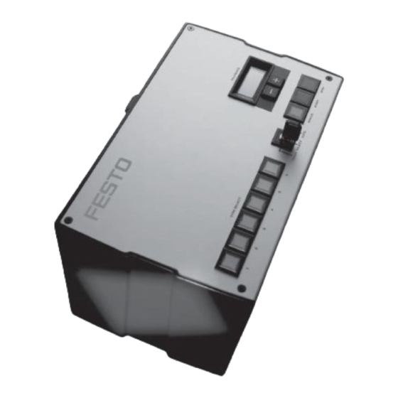
Orientation, tolerance Illuminated buttons for mo- – STATUS (yellow) Status display / error quitting nitoring and controlling the – START (green) Switching on operating status – STOP (red) Switching off Fig. 4/1: Control panel of the Checkbox Festo P.BE-Checkbox-EN en 0103c... -
Page 74: Switching On And Off
3. Connecting the power supply 4. Configuration of the connectings “Sensors” and “Con- troller”: Insert (blanking) plugs or connect the control cables for buffer zone sensors. Mains switch LCD TOLERANCE START button STOP button Fig. 4/2: Operating panel Festo P.BE-Checkbox-EN en 0103c... - Page 75 Switch off the Checkbox as follows: 1. Press the STOP button. The STOP button is lit continu- ously. The conveyor belt remains at a stand. 2. Switch off the mains switch on the connection side of the controller. Festo P.BE-Checkbox-EN en 0103c...
-
Page 76: Operating Modes Of The Checkbox
Accept good part only in nominal orientation or in all orientations Selecting and setting the counter function AUTO mode In the AUTO mode the test procedure runs automatically and can only be influenced manually by means of the START/ STOP buttons. Festo P.BE-Checkbox-EN en 0103c... -
Page 77: Error Diagnosis
E 40...43 Loss of data Teach data, configuration data or system parameters are not compa- tible or do not exist >=E 60 hardware error Internal error (can only be rectified by after-sales service) Festo P.BE-Checkbox-EN en 0103c... - Page 78 A detailed list of the codes and instructions on eliminating faults can be found in Appendix A.1. After eliminating faults: Quit the error message with the STATUS button. Press the STOP button, then the START button. Festo P.BE-Checkbox-EN en 0103c...
- Page 79 Teaching parts with the Checkbox Chapter 5 Festo P.BE-Checkbox-EN en 0103c...
- Page 80 ..........5-11 Festo P.BE-Checkbox-EN en 0103c...
-
Page 81: Preparing The Teach Procedure
“good” should possess. Use different sample parts with a usual scatter of fea- tures. With the scatter of features, you can determine the extent to which test parts later classified as “good” may deviate from each other. Festo P.BE-Checkbox-EN en 0103c... - Page 82 Exceptionally large conveyed parts made of heavy ma- terial (e.g. steel) with streamlined shape may, under cer- tain circumstances, not be blown down. Carry out a test to make sure that the conveyed parts are blown down. Festo P.BE-Checkbox-EN en 0103c...
-
Page 83: Set Operating Mode Teach
3. Set operating mode TEACH with the key switch. 4. Press the green START button. The LCD TOLERANCE shows the current setting of the memory group. The START button lights up; the coveyor belt remains at a stand. Festo P.BE-Checkbox-EN en 0103c... -
Page 84: The Teach Procedure
= maximum 96). Sortbox With the Sortbox, the sorting program is specified by the as- signment of a memory group. The number of sorting pro- grams corresponds therefore to the number of memory groups of the Checkbox. Festo P.BE-Checkbox-EN en 0103c... -
Page 85: Scanning Sample Parts
The conveyor belt runs during the complete scanning pro- cedure. If you press the STOP button, the teach procedure will be discontinued. The currently registered data will be ignored and the complete teach procedure must be repeated. Festo P.BE-Checkbox-EN en 0103c... - Page 86 Different contours of the part, depending on the angle of rotation around the longitudinal axis (e.g. with springs, screws). – Different positioning on the belt. A detailed description of the computational algorithm of the scatter of characteristics can be found in Appendix A.3.2. Festo P.BE-Checkbox-EN en 0103c...
- Page 87 If the C-value shown changes considerably, this indicates that the conveyed part has been positioned incorrectly. 1. Press the STOP button to interrupt the teach procedure. 2. Repeat the complete teach procedure for the parts type. Festo P.BE-Checkbox-EN en 0103c...
- Page 88 Check whether there is at least one feature in which the various orientations differ. Make sure in particular that orientation 1 (nominal orientation) differs clearly in at least one feature from all the other orientations. 5-10 Festo P.BE-Checkbox-EN en 0103c...
-
Page 89: Saving Teach Data
Countbox, Sortbox: If it is not necessary to distinguish the nominal orien- tation: 1. Turn the key switch to TEACH. 2. Switch on the illuminated button on the LCD COUNTER. 3. Repeat the teach procedure. 5-11 Festo P.BE-Checkbox-EN en 0103c... - Page 90 Register the next parts type in a further teach procedure. In order to do this repeat all the steps as from section 5.1.1. Check the completed teach procedure in test mode, and pay attention to orientation and quality as described in chapter 6. 5-12 Festo P.BE-Checkbox-EN en 0103c...
- Page 91 Testing parts with the Checkbox Chapter 6 Festo P.BE-Checkbox-EN en 0103c...
- Page 92 ........6-18 Festo P.BE-Checkbox-EN en 0103c...
-
Page 93: Testing Parts With The Checkbox
All settings in the SELECT operating mode are made while the conveyor belt is running. Prepare the Checkbox as follows: 1. Carry out teach procedure (see chapter 5). 2. Set key switch to SELECT. 3. If the STOP button is pressed down, press the START button. Festo P.BE-Checkbox-EN en 0103c... -
Page 94: Load The Teach Data
TYPE SELECT [...] button. The conveyor belt starts again. The LCD TOLERANCE shows the selected memory group and the tolerance in per cent. 2. Set further parameters or start with the test mode (chapter 6.2). Festo P.BE-Checkbox-EN en 0103c... - Page 95 1. Select the new parts type with the illuminous button TYPE SELECT [...]. The conveyor belt starts again. The LCD TOLERANCE shows the selected memory group and the tolerance in per cent. 2. Set further parameters or start with the test mode (chapter 6.2). Festo P.BE-Checkbox-EN en 0103c...
-
Page 96: Set The Tolerance
1. The value selected will automatically be added to the data of the parts type and saved. With critical conveyed parts, you must ascertain the optimum setting of the tolerance in test mode (see chapter 6.2). Festo P.BE-Checkbox-EN en 0103c... -
Page 97: Enable The Orientations (Countbox, Sortbox)
The set nominal number or the current counter status as desired Current Actual is then shown on the LCD counter status COUNTER. !) Display only in AUTO mode. The counter function is not activated in the operating modes TEACH and SELECT. Festo P.BE-Checkbox-EN en 0103c... - Page 98 3. After 1.5 s the LCD COUNTER changes to represent the nominal number (presetting: 9.9.9.9 = 9999*10#). Numerical values from 1 to 9999 are shown uncoded in the LCD. Larger numerical values are shown with addittional mul- tipliers (points) see chapter A2, section “Representation of numbers”. Festo P.BE-Checkbox-EN en 0103c...
- Page 99 Set nominal value to “0”. Hold COUNTER [+] and [-] pressed down simultaneously until the display is deleted (min. 3 s). If, in AUTO mode, the current counter status is to be shown, set the counter type “Actual”. Festo P.BE-Checkbox-EN en 0103c...
-
Page 100: Test Mode
You must check a sufficient number of parts in order to obtain a reproducible result. Show e.g. 6 parts recognized as good and 6 bad parts per orientation. Press the STOP button in order to interrupt or terminate the test mode. 6-10 Festo P.BE-Checkbox-EN en 0103c... - Page 101 If the checked parts are graded reliably according to orienta- tion and quality: Press the STOP button. Switch to the AUTO operating mode in order to start the automatic test (chapter 6.3). 6-11 Festo P.BE-Checkbox-EN en 0103c...
-
Page 102: Visual Check
The Checkbox ascer- tains for each test part the feature which deviates the most (maximum deviation). During the test procedure you can see this test part deviation for 1.5 seconds in the TOLERANCE display. 6-12 Festo P.BE-Checkbox-EN en 0103c... -
Page 103: Checking The Orientation
› 100 Test part orientation The greater the value, cannot be assigned the less reliably the clearly test part orientation can be recognized. Display range: 0 to 999 6-13 Festo P.BE-Checkbox-EN en 0103c... -
Page 104: Influence Of Tolerance On The Test Result
Vary the tolerance so that the following test part deviation is shown when the borderline sample parts are scanned. ‹ 100 for the borderline sample part “good” or ‹ 100 for the borderline sample part “bad”. 6-14 Festo P.BE-Checkbox-EN en 0103c... -
Page 105: Automatic Mode
Sortbox In automatic mode you can use the TYPE SELECT buttons to access the tolerance setting and the current counter status of each parts type of the current sorting program. 6-15 Festo P.BE-Checkbox-EN en 0103c... -
Page 106: Manual Start/Stop Mode
With STOP the current counter states are saved. With START the counting processes are continued with the saved counter states. 6-16 Festo P.BE-Checkbox-EN en 0103c... - Page 107 LCD shows COUNTER FULL and flashes at 1 sec- ond intervals. After the preset time, the small parts conveyor will be switched off. 6-17 Festo P.BE-Checkbox-EN en 0103c...
-
Page 108: Modifying Operating Parameters
SELECT, see chapter 6.1.5. 6.3.4 Modifying operating parameters All settings of the Checkbox are to be made in the operating mode SELECT. Please refer here to the explanations in chapter 6.1.1 ... 6.2.5. 6-18 Festo P.BE-Checkbox-EN en 0103c... - Page 109 Maintenance Chapter 7 Festo P.BE-Checkbox-EN en 0103c...
- Page 110 ............Festo P.BE-Checkbox-EN en 0103c...
- Page 111 Fixed cleaning intervals are not stipulated. The frequency of cleaning depends on the conditions of use at the site. Faultless functioning of the Checkbox optics can only be guar- anteed if the glass surfaces are clean and not scratched. Festo P.BE-Checkbox-EN en 0103c...
- Page 112 It is not necessary to dismantle the protective screen “Lighting” in order to clean it. Clean the glass surface above the conveyor belt: – with clean, non-lubricated compressed air, – with a soft moist cloth and a non-abrasive cleaning agent. Festo P.BE-Checkbox-EN en 0103c...
- Page 113 7. Maintenance Camera cover Protective screen “Camera” Protective screen “Lighting” Lighting Plugs Fig. 7/1: Protective screens Festo P.BE-Checkbox-EN en 0103c...
- Page 114 1. Place the protective screen by its handle carefully back into the screen slot. 2. Tighten the locking screw next to the camera slot by hand. Please note Tighten the screw only by hand. You will then avoid damage to the protective screen. Festo P.BE-Checkbox-EN en 0103c...
- Page 115 Technical appendix Appendix A Festo P.BE-Checkbox-EN en 0103c...
- Page 116 ........... . A-27 Festo P.BE-Checkbox-EN en 0103c...
-
Page 117: Technical Appendix
– Blow-down timing point – Modify blow-down timing blown down at the delivery incorrectly set point points. – Suction effect due to flow – Modify nozzle geometry resistance of conveyed part Festo P.BE-Checkbox-EN en 0103c... - Page 118 Checkbox runs in diagnostic – With CheckKon/CheckOpti: duration of the Checkbox is not mode (setting via CheckKon or Switch from diagnostic mode correct. CheckOpti) to operating mode Test part deviation is shown unusually long on LCD TOLERANCE. Festo P.BE-Checkbox-EN en 0103c...
-
Page 119: Error Messages
– Replace the camera cable E 04 System recognizes too many – Check the selection of the sample part type incorrect conveyed parts: – Increase tolerance > 75 % of the last 20 parts were graded as bad parts Festo P.BE-Checkbox-EN en 0103c... - Page 120 2. Check whether external outputs are loaded with a current too high. 3. Press the START button. Or contact the Festo after-sales service. E 12 No power supply on I/O module – Check the blanking plug on the connection for the higher-order controller.
- Page 121 – the sample part is identical to the parts type of another TYPE SELECT memory loca- tion. – a different orientation of the sample part has been saved on another TYPE SELECT memory location. Festo P.BE-Checkbox-EN en 0103c...
- Page 122 (running light). – With CheckKon: Load system parameters again. – Or contact the Festo after-sales service. E 42 Controller has lost configur- – Load system parameters again from internal safety...
- Page 123 ...E 04 although only a small Moving particles of dirt on the – Clean the conveyor belt with number of bad parts passes conveyor belt. compressed air. the test procedure. – Install a cutting device in front of the conveyor belt. Festo P.BE-Checkbox-EN en 0103c...
-
Page 124: Status Displays On The Control Panel
The counter function is not active in the operat- ing mode TEACH; the LCD COUNTER does not show anything. A-10 Festo P.BE-Checkbox-EN en 0103c... - Page 125 Orientation of the sample parts 1...8 during the teach procedure. Error code for system error. 01...99 Details in chapter A.1.2 Memory address occupied – with measuring tool – or with optimized teach data (CheckOpti). A-11 Festo P.BE-Checkbox-EN en 0103c...
- Page 126 0...999 reliably the test part orientation can be recognized. 100: Test part orientation can be assigned 100: Test part orientation can- not be assigned clearly Error code for system error. 01...99 Details in chapter A.1.2 A-12 Festo P.BE-Checkbox-EN en 0103c...
- Page 127 0...20 1st. number: Parts type or sorting program 2nd. number: Tolerance in % Status of buffer zone (signal from buffer zone sensor) Error code for system error 01...99 Details in chapter A.1.2 A-13 Festo P.BE-Checkbox-EN en 0103c...
- Page 128 Corresponding to the selected 0...9999 * 10 option of the counter function: Without switching off – Production counter With switching off – Nominal value of good parts or – Current counter Preselected counter reading reached A-14 Festo P.BE-Checkbox-EN en 0103c...
- Page 129 10 for each deci- mal point. Numerical value Multiplication Number 9 9 9 9 9999 1.0 0 0 1000 x 10 10000 1.0.0 0 1000 x 10 100000 1.0.0.0 1000 x 10 1000000 A-15 Festo P.BE-Checkbox-EN en 0103c...
-
Page 130: Calculation Examples
B (C Average value of the feature Bandwidth Feature - maximum Upper limit of bandwidth incl. tolerance max tol Feature - minimum Lower limit of bandwidth incl. tolerance min tol Tolerance A-16 Festo P.BE-Checkbox-EN en 0103c... - Page 131 Bandwidth of conveyed part length Bandwidth with 5 % tolerance Result: All conveyed parts with a length of 57...68 mm are classified as good parts. The Checkbox ascertains appropri- ate value ranges for each feature. A-17 Festo P.BE-Checkbox-EN en 0103c...
-
Page 132: Scatter Of Characteristics
“Length” of a conveyed part. The following values are taken from the example “Bandwidth” = 61.2 Average value of the length = 65 Length - maximum = 60 Length - minimum 65 60 100 % 61.2 8.2 % A-18 Festo P.BE-Checkbox-EN en 0103c... -
Page 133: Feature Deviation
The following values are taken from the example “Bandwidth” = 61.2 Average value of the length = 56.94 Length - lower value min tol = 61 Length - current value actual 61 61.2 100 % 56.94 61.2 4.7 % A-19 Festo P.BE-Checkbox-EN en 0103c... - Page 134 The following values are taken from the example “Bandwidth” = 61.2 Average value of the length = 68.06 Length – upper value max tol = 64 Length - current value actual 64 61.2 100 % 68.06 61.2 41.8 % A-20 Festo P.BE-Checkbox-EN en 0103c...
-
Page 135: Pin Assignment
Cleaning valve Not assigned Not assigned Not assigned O/20 Actuator 6 Actuator 6 Actuator 6 O/21 Error status 2 Error status 2 Error status 2 O/22 Error status 0 Error status 0 Error status 0 A-21 Festo P.BE-Checkbox-EN en 0103c... - Page 136 As standard the built-in pressure sensor of the Checkbox is monitored. If an external pressure sensor is to be connected via I/36, the Checkbox configuration must be adapted accordingly. Please consult the Festo after-sales service. A-22 Festo P.BE-Checkbox-EN en 0103c...
- Page 137 The sensor inputs are negative-switching (normally-closed). If 24 V DC is applied, the small parts conveyor will be switched on. As an option, direct connection with a Festo DUO cable is also pos- sible. Cable designation signal x (= I/1), signal x+1 (= I/2).
-
Page 138: Technical Specifications
Compressed air supply 4...6 bar overpressure Electric components Power supply (self setting) 85...264 V / 50...60 Hz via a backup fuse of 1 A (slow- blowing) in the mains switch Power consumption Max. 150 VA A-24 Festo P.BE-Checkbox-EN en 0103c... - Page 139 5x50 mm tested and in correct position The conveyor rate depends on the size of the component, the number of orientations and the belt speed. Dimensions, weight Controller: Dimensions and weight Height [mm] Width [mm] Depth [mm] Weight [kg] A-25 Festo P.BE-Checkbox-EN en 0103c...
- Page 140 Conveyor unit dimensions Rotation-symmetric or pre-orientated parts Dimensions Conveyor unit for conveyed part @ 10 mm @ 30 mm @ 80 mm Length [mm] 3...50 3...80 5...80 Diameter [mm] 0.5...10 3...30 3...80 Further lengths on request A-26 Festo P.BE-Checkbox-EN en 0103c...
-
Page 141: Accessories
4-pin spare plug for buffer zone sensors 37-pin spare plug for a higher-order controller 37-pin spare plug for a higher-order controller with 5 m cable length Mounting plates for build-on parts to the conveyor unit Mounting plate, supply Mounting plate, exit A-27 Festo P.BE-Checkbox-EN en 0103c... - Page 142 A. Technical appendix A-28 Festo P.BE-Checkbox-EN en 0103c...
- Page 143 Brief instructions Appendix B Festo P.BE-Checkbox-EN en 0103c...
- Page 144 ..........Festo P.BE-Checkbox-EN en 0103c...
- Page 145 TEACH: for carrying out the teach procedure. – SELECT: for saving the teach data, setting the operating parameters and for checking the conveyed parts in test mode. – AUTO: for checking the conveyed parts in automatic mode. Festo P.BE-Checkbox-EN en 0103c...
- Page 146 - without the bridge fitted at the factory - with sensors connected at both sensor inputs. Screw the plug into the connection “Sensors”. S Also insert the plug “Controller” wired at the factory into the connection “Controller”. Festo P.BE-Checkbox-EN en 0103c...
- Page 147 Screw the plug into the connection “Controller”. S Use the plug “Sensors” at the connection “Sensors” - without the bridges fitted at the factory between the sensor inputs and 24 V DC. Screw the plug into the connection “Sensors”. Festo P.BE-Checkbox-EN en 0103c...
- Page 148 TOLERANCE [+]. 4. Scan sample parts in the new orientation. Saving teach data Switch to the operating mode SELECT with the key switch. The sorting program is defined for the Sortbox when a memory group is assigned. Festo P.BE-Checkbox-EN en 0103c...
- Page 149 1. Visual check, check of the blow-down positions and the blow-down procedure 2. Max. feature deviation of the test part (test part deviation < 100 ?) 3. Check of orientation (position deviation < 100 ?) 4. Check influence of the tolerance Festo P.BE-Checkbox-EN en 0103c...
- Page 150 RANCE shows the memory group and the tolerance in per cent. current memory The LCD COUNTER shows in faultless opera- group and the tion the counter status or the nominal num- tolerance in per ber. cent. Festo P.BE-Checkbox-EN en 0103c...
- Page 151 Index Appendix C Festo P.BE-Checkbox-EN en 0103c...
- Page 152 ............Festo P.BE-Checkbox-EN en 0103c...
- Page 153 ........Festo P.BE-Checkbox-EN en 0103c...
- Page 154 ....... . . Error/fault Eliminating faults ....... Festo P.BE-Checkbox-EN en 0103c...
- Page 155 Operating system ....... . . XIII Festo P.BE-Checkbox-EN en 0103c...
- Page 156 ........4-3, 4-4 Festo P.BE-Checkbox-EN en 0103c...
- Page 157 ......... 2-5, 2-6 Festo P.BE-Checkbox-EN en 0103c...
- Page 158 C. Index Festo P.BE-Checkbox-EN en 0103c...
Need help?
Do you have a question about the Checkbox Series and is the answer not in the manual?
Questions and answers