
Related Manuals for Festo CTEU-EC


Summary of Contents for Festo CTEU-EC
- Page 1 Universal bus node CTEU-EC Description, functions and maintenance Bus node Type CTEU-EC Network protocol EtherCAT Description 575401 en 1208NH [758875]...
- Page 3 ........575401 © (Festo AG & Co. KG, D-73726 Esslingen, 2012) Internet: http://www.festo.com E-mail: service_international@festo.com...
- Page 4 Contents and general safety instructions ® ® ® ® EtherCAT , TwinCAT , CANopen and TORX are registered trademarks of the respective trademark owners in certain countries. Festo P.BE-CTEU-EC-OP+MAINT-EN en 1208NH...
-
Page 5: Table Of Contents
Configuration of operating behaviour (target configuration) ..2-13 2.1.5 Addressing and data access (data objects) ....2-19 Festo P.BE-CTEU-EC-OP+MAINT-EN en 1208NH... - Page 6 ............Festo P.BE-CTEU-EC-OP+MAINT-EN en 1208NH...
-
Page 7: Designated Use
Contents and general safety instructions Designated use The bus node type CTEU-EC described in this manual has been designed exclusively for use as a participant (slave device) in an EtherCAT network. The bus node may only be used as follows: –... -
Page 8: Range Of Application And Certifications
You can find information on EtherCAT online at: www.ethercat.org Target group This manual is intended exclusively for technicians trained in control and automation technology, who have experience in installation, commissioning, programming and diagnostics of programmable logic controllers (PLC) and fieldbus systems. Festo P.BE-CTEU-EC-OP+MAINT-EN en 1208NH... -
Page 9: Service
Contents and general safety instructions Service Please consult your local Festo Service agent if you have any technical problems. Festo P.BE-CTEU-EC-OP+MAINT-EN en 1208NH... -
Page 10: Notes On This Manual
Information relating to installation of the bus node can be found in Part I of the product documentation entitled “Universal bus node CTEU-EC – Installation and Interface manual”, which is supplied with the bus node. All information relating to installation and to the interfaces can also be found in chapter 1 of this manual. - Page 11 Switched Fast Ethernet, 100 Mbit/s Standards and norms containing reference to EtherCAT: – IEC 61158 – IEC 61784 – IEC 61918 – ISO/IEC 8802-3 Additional information: http://www.ethercat.org Tab. 0/1: Overview of CTEU bus node for EtherCAT Festo P.BE-CTEU-EC-OP+MAINT-EN en 1208NH...
-
Page 12: Important User Instructions
... means that failure to observe this instruction may result in material damage. In addition, the following pictogram denotes passages in the text which describe activities involving electrostatically sens- itive devices: Electrostatically sensitive devices: Incorrect handling may cause damage to devices. Festo P.BE-CTEU-EC-OP+MAINT-EN en 1208NH... - Page 13 Pictograms Information: Recommendations, tips and references to other information sources. Accessories: Information on necessary or useful accessories for the Festo product. Environment: Information on the environmentally friendly use of Festo products. Text designations Bullet points denote activities that may be carried out in •...
- Page 14 I/Os Digital inputs and outputs Input byte Industrial PC I-port Festo-specific port for the transfer of communication data (process data, sensor signals, pilot signals) and supply voltages Tab. 0/2: Specific terms and abbreviations – part 1 Festo P.BE-CTEU-EC-OP+MAINT-EN en 1208NH...
- Page 15 These permit write and read access to any entry in the object directory of a bus node. TwinCAT Beckhoff configuration and programming software (TwinCAT: The Windows Control and Automation Technology) Tab. 0/3: Specific terms and abbreviations – part 2 XIII Festo P.BE-CTEU-EC-OP+MAINT-EN en 1208NH...
- Page 16 Contents and general safety instructions Festo P.BE-CTEU-EC-OP+MAINT-EN en 1208NH...
-
Page 17: Installation
Installation Chapter 1 Installation Festo P.BE-CTEU-EC-OP+MAINT-EN en 1208NH... - Page 18 ........1-12 1.4.5 Basic settings for fieldbus communication ....1-14 Festo P.BE-CTEU-EC-OP+MAINT-EN en 1208NH...
-
Page 19: General Information On The Cteu Product Family
The CTEU… product family is used to set up a decentralised automation system in an EtherCAT fieldbus network. 1.1.1 Hardware components Higher-order controller (master/PLC/IPC) Fieldbus level: bus node CTEU Device level: e.g. valve terminal VTUB-12 Drive level: e.g. linear module HME Festo P.BE-CTEU-EC-OP+MAINT-EN en 1208NH... -
Page 20: Scope Of Functions (Brief Overview)
1. Installation The fieldbus and device levels are connected via an I-port. I-port is a Festo-specific port for the transmission of commu- nication data (process data, sensor signals, pilot signals) and supply voltage. The I-port communication protocol is based on the IO-Link protocol. The electrical and mechanical connec- tions between the bus node and I-port device are standard- ised. -
Page 21: General Information On The Ethercat Fieldbus Protocol
For this, each slave requires two EtherCAT interfaces (one for trans- mission and one for reception). The CTEU-EC bus node supports the CANopen over EtherCAT (CoE) and File Access over EtherCAT (FoE) protocols. Participant addressing In an EtherCAT network, the slaves are automatically as- signed addresses. -
Page 22: Ethercat Specifications
Further information on EtherCAT is available online: EtherCAT specifications EtherCAT http://www.ethercat.org/en/publications.html Technology Group Tab. 1/1: EtherCAT specifications 1.2.3 Conformance with the EtherCAT specifications The CTEU-EC bus node gave a positive result in testing with the “EtherCAT Conformance Test Tool” (CTT, Version 1.20.52.0). Festo P.BE-CTEU-EC-OP+MAINT-EN en 1208NH... -
Page 23: General Information On Installation
Note The EtherCAT bus node contains electrostatically sensitive components. Do not touch any electrical or electronic components. • Observe the handling specifications for electrostatically • sensitive devices. This will help to prevent damage to the electronics. Festo P.BE-CTEU-EC-OP+MAINT-EN en 1208NH... - Page 24 For H-rail mounting, you will also need mounting kit CAFM-... (CAPC and CAFM). For mounting the bus node, a valve terminal from Festo, or electrical connection box type CAPC-... with I-port interface, is required.
-
Page 25: Interfaces
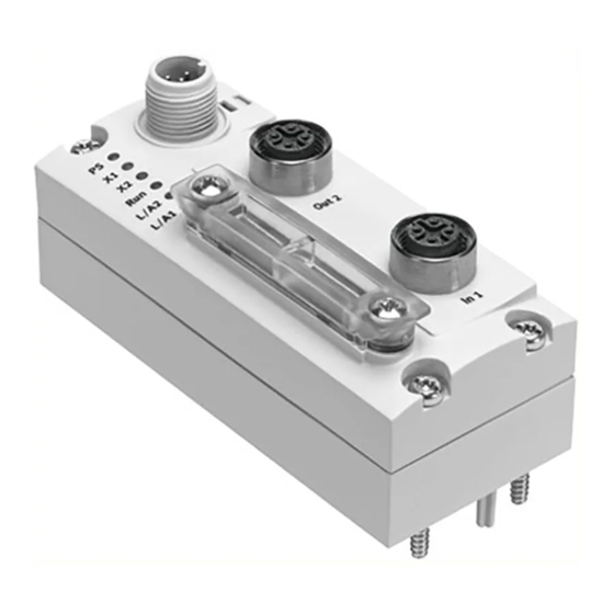
3.2) Power supply connection for bus node and any connec- ted devices, e.g. valve terminal; M12, 5-pin, A-coded, pin plug connector section 1.4.2) Fieldbus connections (fieldbus interfaces): 2x M12, 4-pin, socket plug connector, D-coded section 1.4.4) Festo P.BE-CTEU-EC-OP+MAINT-EN en 1208NH... -
Page 26: Power Supply
Always connect the circuits for both operating and load • voltage supply. The use of PELV circuits ensures protection from electric shock (protection from direct and indirect contact) in accord- ance with IEC/EN 60204-1 (Electrical equipment of machines, General requirements). 1-10 Festo P.BE-CTEU-EC-OP+MAINT-EN en 1208NH... - Page 27 CAPC-... For the connection to power supply units or the power supply, use cables with M12 coupling (socket plug connector), A-coded, in accordance with IEC 61076-2 Accessories www.festo.com/catalogue. 1-11 Festo P.BE-CTEU-EC-OP+MAINT-EN en 1208NH...
-
Page 28: Functional Test - Without Network Connection
EtherCAT user organisation: – EtherCAT Technology Group: http://www.ethercat.org/ – EtherCAT-specifications (“EtherCAT Specification”, “Profiles”), guidelines (“Guidelines”) and instructions (e.g. “How to Configure an EtherCAT Slave Device”): http://www.ethercat.org/en/publications.html Observe the instructions in these documents. 1-12 Festo P.BE-CTEU-EC-OP+MAINT-EN en 1208NH... - Page 29 22 AWG (for 100 m link length, based on ISO/IEC 11801). Note If installation has not been carried out correctly and if high baud rates are used, data transmission errors may occur as a result of signal reflections and attenuations. 1-13 Festo P.BE-CTEU-EC-OP+MAINT-EN en 1208NH...
-
Page 30: Basic Settings For Fieldbus Communication
– EtherCAT address (“station number”, optional) – Diagnostic functionality (transmission of diagnostic information as emergency messages (EM) into the diagnostic history) – Fail state mode To set the DIL switches, you must remove the cover. 1-14 Festo P.BE-CTEU-EC-OP+MAINT-EN en 1208NH... - Page 31 Tighten the two mounting screws with a max. torque of • 0.4 Nm. Proceed as follows: 1. Switch off the power supply. 2. Unscrew the two mounting screws of the transparent cov- er and remove the cover. 1-15 Festo P.BE-CTEU-EC-OP+MAINT-EN en 1208NH...
- Page 32 Optional, e.g. for Hot Connect function If the PLC is in stop (EtherCAT: PRE-OPERATIONAL) mode or the fieldbus connection is interrupted (fail state); applies for all outputs Note: Fail-state mode is also known as “fail-safe mode” 1-16 Festo P.BE-CTEU-EC-OP+MAINT-EN en 1208NH...
- Page 33 Mounting the DIL switch cover 1. Place the cover carefully on the bus node. Make sure that the seal is seated correctly. 2. Tighten the two mounting screws with a max. torque of 0.4 Nm. 1-17 Festo P.BE-CTEU-EC-OP+MAINT-EN en 1208NH...
- Page 34 1. Installation 1-18 Festo P.BE-CTEU-EC-OP+MAINT-EN en 1208NH...
-
Page 35: Commissioning
Commissioning Chapter 2 Commissioning Festo P.BE-CTEU-EC-OP+MAINT-EN en 1208NH... - Page 36 ..2-22 2.2.3 Replacing the I-port device – different device type (replacement) 2-23 2.2.4 Replacing the electrical connection box CAPC-… ....2-24 Festo P.BE-CTEU-EC-OP+MAINT-EN en 1208NH...
-
Page 37: Configuration
Hot Connect can access this predefined address thanks to the option of address reservation in the CTEU-EC bus node using DIL switches ( section 1.4.5). The first EtherCAT participant after the master should not be a Hot Connect-configured participant, as this will slow down link detection at the master. - Page 38 The ESI file contains all the information needed for the config- uration and settings of the higher-order controller using con- figuration and programming software, e.g. Beckhoff TwinCAT. The ESI file for the CTEU-EC bus node is available in two vari- ants. Modular ESI file This file requires that the I/O data are configured according to the devices connected to the I-port.
- Page 39 2. Commissioning The CTEU-EC bus node is supplied ready for use with the modular ESI file. In order for the fixed ESI file to be used, the EEPROM must be updated ( section A.3) with the help of the configuration and programming software.
- Page 40 When the ESI file is imported, e.g. the following information is sent to the configuration program via the bus node/EtherCAT participant. Information Description Vendor name Festo AG & Co. KG Vendor ID 0x0000001D Product code 572556 Version number Hardware version: V1.11 Software version: V4.42.3...
-
Page 41: Configuration Of The Operating Modes
2. Commissioning 2.1.3 Configuration of the operating modes Depending on the application, the CTEU-EC bus node permits manual configuration as an alternative to automatic configur- ation. In automatic configuration (auto mode), the connected devices are automatically read in. In this case, however, the configuration defined must match the connected devices. - Page 42 Only if the I-port configuration “expect device” is se- lected is the message “Output data size is greater than configured” generated when a device with an I/O length greater than that configured in tool change mode is connected ( section 2.1.4). Festo P.BE-CTEU-EC-OP+MAINT-EN en 1208NH...
- Page 43 A VTUB valve terminal is connected to slot 2 in auto mode. Configuration is carried out via Modular Device Profile (MDP). Fig. 2/2: Example: configuration of slot 1 in tool change mode and slot 2 in auto mode (VTUB valve terminal) Festo P.BE-CTEU-EC-OP+MAINT-EN en 1208NH...
- Page 44 2. Commissioning Fig. 2/3: Activation of tool change mode for slot 1 2-10 Festo P.BE-CTEU-EC-OP+MAINT-EN en 1208NH...
- Page 45 2. Commissioning Fig. 2/4: Definition of input data (here 8 bytes) 2-11 Festo P.BE-CTEU-EC-OP+MAINT-EN en 1208NH...
- Page 46 2. Commissioning Fig. 2/5: Definition of output data (here 8 bytes) Fig. 2/6: Defined startup configuration for a slot 2-12 Festo P.BE-CTEU-EC-OP+MAINT-EN en 1208NH...
-
Page 47: Configuration Of Operating Behaviour (Target Configuration)
CoE object Value Operating behaviour (hex.) 0x8100 0x00 Use responding device (standard setting) 0x01 Expect device 0x02 Port disabled 0x810A 0x00 Use responding device (standard setting) 0x01 Expect device 0x02 Port disabled Tab. 2/6: Operating behaviour 2-13 Festo P.BE-CTEU-EC-OP+MAINT-EN en 1208NH... - Page 48 2. Commissioning Use responding device (standard setting) The CTEU-EC bus node starts up in this operating mode by default. A device can be connected to the I-port, but this is not essential. Auto mode Tool change mode If a device is disconnected from the I-port during A fixed address space is reserved in the image operation, the “device disconnected”...
- Page 49 “device reconnected”) as soon as the connection ror is signalled at the relevant port until the to the device is reestablished. device is disconnected from that port. All other I-ports will remain active and usable. 2-15 Festo P.BE-CTEU-EC-OP+MAINT-EN en 1208NH...
- Page 50 2. Commissioning Fig. 2/7: Example: value 01 for slot 1 means “expect device” ( Tab. 2/6) 2-16 Festo P.BE-CTEU-EC-OP+MAINT-EN en 1208NH...
- Page 51 All other ports can contin- ue to be used. If the device is disconnected again from the re- spective I-port, this configuration error is auto- matically reset. 2-17 Festo P.BE-CTEU-EC-OP+MAINT-EN en 1208NH...
- Page 52 2. Commissioning Fig. 2/8: Example: value 02 for slot 2 means “port disabled” ( Tab. 2/6) 2-18 Festo P.BE-CTEU-EC-OP+MAINT-EN en 1208NH...
-
Page 53: Addressing And Data Access (Data Objects)
EtherCAT devices within the network. Block-oriented addressing (i.e. not module-oriented addressing as used by other fieldbus systems) is used. Alternatively, the CTEU-EC bus node can be assigned an EtherCAT address using the DIL switches ( section 1.4.5). - Page 54 A valve terminal will be put into operation even if it is in- correctly configured. Before commissioning, ensure that the connected ele- • ments (e.g. actuators) do not perform any unexpected or uncontrollable movements. If necessary, disconnect the load power supply and com- • pressed air supply. 2-20 Festo P.BE-CTEU-EC-OP+MAINT-EN en 1208NH...
-
Page 55: Replacing The Device
6. If relevant, switch the compressed air supply back on. 7. Start the program sequence (PLC/master); do this by se- lecting the EtherCAT operating status “OPERATIONAL”. Your EtherCAT system is again in normal operating mode. 2-21 Festo P.BE-CTEU-EC-OP+MAINT-EN en 1208NH... -
Page 56: Replacing The I-Port Device - Same Device Type (Substitute)
1. Do not switch off the bus node power supply. 2. Remove the bus node from the I-port device (Dismantling/Mounting: section 1.3). 3. Mount the bus node on the new I-port device (Dismantling/Mounting: section 1.3). The bus node detects the connected I-port device. 2-22 Festo P.BE-CTEU-EC-OP+MAINT-EN en 1208NH... -
Page 57: Replacing The I-Port Device - Different Device Type (Replacement)
(Dismantling/Mounting: section 1.3). The bus node detects the connected I-port device. If the image table exceeds the currently defined I/O data length, the excess bytes will be excluded. Notes on tool change mode section 2.1.3 2-23 Festo P.BE-CTEU-EC-OP+MAINT-EN en 1208NH... -
Page 58: Replacing The Electrical Connection Box Capc
“CAPC-F1-E-M12-D2” User documentation. 4. Mount the bus node on the new electrical connection box (Dismantling/Mounting: section 1.3). 5. Switch the bus node power supply on again. The bus node detects the connected I-port devices. 2-24 Festo P.BE-CTEU-EC-OP+MAINT-EN en 1208NH... - Page 59 “CAPC-F1-E-M12-D2” User documentation. 4. Mount the bus node on the new electrical connection box (Dismantling/Mounting: section 1.3). 5. Switch the bus node power supply on again. The bus node detects the connected I-port devices. 2-25 Festo P.BE-CTEU-EC-OP+MAINT-EN en 1208NH...
- Page 60 2. Commissioning 2-26 Festo P.BE-CTEU-EC-OP+MAINT-EN en 1208NH...
-
Page 61: Diagnostics
Diagnostics Chapter 3 Diagnostics Festo P.BE-CTEU-EC-OP+MAINT-EN en 1208NH... -
Page 62: Summary Of Diagnostics Options
........3-15 3.3.7 Error reaction (fail-state settings) ......3-19 Festo P.BE-CTEU-EC-OP+MAINT-EN en 1208NH... -
Page 63: Diagnostics
Diagnostics via LED display There are LEDs on the bus node to assist in diagnostics on the bus node and any connected devices Fig. 3/1). The LEDs can assume the following states (sometimes in dif- ferent colours): Illuminated Flashing Festo P.BE-CTEU-EC-OP+MAINT-EN en 1208NH... - Page 64 (Link/Activity) Out2 L/A1: Connection status (Link/Activity) Fig. 3/1: LEDs on the bus node After the switch-on procedure the status LEDs indicate the operating status and correct function of the bus node and of fieldbus communication. Festo P.BE-CTEU-EC-OP+MAINT-EN en 1208NH...
-
Page 65: Ps Led Status Display
Operating voltage not present Check the power supply LED is off Display depends on whether the connected device monitors the load voltage and reports this to the bus node Tab. 3/2: Status displays of the device-specific “PS” LED Festo P.BE-CTEU-EC-OP+MAINT-EN en 1208NH... -
Page 66: Status Display X1/X2 Leds
1) Separate accessory (electrical connection box, type CAPC-…) with two interfaces for connecting another device is required. Tab. 3/3: Status displays of the device-specific “X1” LEDs if a device 1 is connected and “X2” if a device 2 is connected Festo P.BE-CTEU-EC-OP+MAINT-EN en 1208NH... - Page 67 1) Separate accessory (electrical connection box, type CAPC-…) with two interfaces for connecting another device is required. Tab. 3/4: Status displays of the device-specific “X1” LEDs if a device 1 is connected and “X2” if a device 2 is connected (continuation of Tab. 3/3) Festo P.BE-CTEU-EC-OP+MAINT-EN en 1208NH...
-
Page 68: Ethercat Operating Status Display (Led Run)
LED not illuminated Single brief flash (1 x flash, pause, 1 x flash, etc.) is designated as single flash. Tab. 3/5: Error diagnostics with the run LED Festo P.BE-CTEU-EC-OP+MAINT-EN en 1208NH... - Page 69 • No physical network connection Check network connection/ network cable LED not illuminated Rapid flickering gives impression that LED is lit; light intensity depends on data traffic Tab. 3/6: Error diagnostics with the LEDs L/A2, L/A1 Festo P.BE-CTEU-EC-OP+MAINT-EN en 1208NH...
-
Page 70: Diagnostics Via Ethercat
TwinCAT system manager. The following table shows the structure of the diagnostics object 0x10F3. The following abbreviations are used: RO = read only RW = read/write RO P = read only (PDO mappable) 3-10 Festo P.BE-CTEU-EC-OP+MAINT-EN en 1208NH... - Page 71 An existing diagnostics message must first be acknowledged before it can be overwritten with a new diagnostics message. When the number of unconfirmed diagnostics messages reaches 20, subsequent diagnostics messages will not be saved and will be lost. 3-11 Festo P.BE-CTEU-EC-OP+MAINT-EN en 1208NH...
- Page 72 If several emergency messages from Tab. 3/9 are present, only the most recently reported is transmitted to the mas- ter controller. The following sections describe the components of the emer- gency message and the error causes Tab. 3/9 ... Tab. 3/11). 3-12 Festo P.BE-CTEU-EC-OP+MAINT-EN en 1208NH...
-
Page 73: Error Codes
– No device at either I-port • Built-in self test failed Restart device • Contact support Other diagnostic message – Diagnostic bytes from I-port telegram present (I-port event codes, Tab. 3/11) Tab. 3/9: Bus node error codes 3-13 Festo P.BE-CTEU-EC-OP+MAINT-EN en 1208NH... - Page 74 Communication error Node guard, heartbeat – fieldbus-specific only – Not used Reserved (always 0) Always 0 Manufacturer specific Always set if error is not 1 … 6 or diagnostics program from I-port Tab. 3/10: Error register 3-14 Festo P.BE-CTEU-EC-OP+MAINT-EN en 1208NH...
-
Page 75: I-Port Event Code
Replace batteries General power supply fault – General fault in power supply • Check availibility Check availability Fuse blown/open - Exchange Fuse has tripped or is not fuse correctly inserted • Replace fuse or insert correctly 3-15 Festo P.BE-CTEU-EC-OP+MAINT-EN en 1208NH... - Page 76 Wire break in subordinate device 1 ... 15 – Check device 1 … 15 • installation Check installation Short circuit – Check Short circuit • installation Check installation Ground fault – Check Earth connection • installation Check installation 3-16 Festo P.BE-CTEU-EC-OP+MAINT-EN en 1208NH...
- Page 77 Connection to I-port device reestablished • Device configuration failed Compare target configuration with the I-ports used • Then restart • Device wrongly connected Remove device from the respective I-port • Device missing Connect device to I-port 3-17 Festo P.BE-CTEU-EC-OP+MAINT-EN en 1208NH...
- Page 78 • No action required Output data size greater than Output data are greater than configured those configured in tool change mode • No action required Tab. 3/11: I-port event code 3-18 Festo P.BE-CTEU-EC-OP+MAINT-EN en 1208NH...
-
Page 79: Error Reaction (Fail-State Settings)
(or the application program): – Hard error reaction: The controller switches to “STOP”/PRE-OPERATIONAL mode when a fault occurs – Soft error reaction: The controller remains in “RUN”/SAFE-OPERATIONAL (or, if relevant, OPERATIONAL) mode when a fault occurs 3-19 Festo P.BE-CTEU-EC-OP+MAINT-EN en 1208NH... - Page 80 – using an input signal in the controller to check whether the load voltage has been switched off – blocking the valve switching signal by locking the output signal with the “load voltage” input signal 3-20 Festo P.BE-CTEU-EC-OP+MAINT-EN en 1208NH...
- Page 81 – Monostable valves will move to their normal position – Double-solenoid valves will remain in their current posi- tion – Mid-position valves will move to their neutral position (pressurised, exhausted or closed, depending on valve type) 3-21 Festo P.BE-CTEU-EC-OP+MAINT-EN en 1208NH...
- Page 82 3. Diagnostics 3-22 Festo P.BE-CTEU-EC-OP+MAINT-EN en 1208NH...
-
Page 83: Technical Appendix
Technical appendix Appendix A Technical appendix Festo P.BE-CTEU-EC-OP+MAINT-EN en 1208NH... -
Page 84: Technical Data
Communication profile – extensions, fixed variant ... . . A-14 A.4.3 Communication profile – extensions, modular variant ..A-17 Festo P.BE-CTEU-EC-OP+MAINT-EN en 1208NH... - Page 85 The device is intended for use in an industrial environment. Outside of industrial environments, e.g. in commercial and mixed-residential areas, measures to suppress interference may be required. Explanation of severity level following table “Explanation of vibration and shock – severity level” Festo P.BE-CTEU-EC-OP+MAINT-EN en 1208NH...
-
Page 86: Technical Appendix
(SG2, in accordance with EN 60068, 0.35 mm path at 10 … 60 Hz; part 2 – 27) 5 g acceleration at 60 ... 150 Hz Shock: ±30 g at 11 ms duration; 5 shocks per direction Continuous shock: n. a. Festo P.BE-CTEU-EC-OP+MAINT-EN en 1208NH... - Page 87 Dependent on the connected device (e.g. valve terminal) Load capacity with regard to the connected equipment, e.g. the valve terminal, including the bus node I-port interface signal transmission – Internal cycle time 1 ms per 1 byte of user data Festo P.BE-CTEU-EC-OP+MAINT-EN en 1208NH...
- Page 88 Standards and norms containing reference to EtherCAT: – IEC 61158 – IEC 61784 – IEC 61918 – ISO/IEC 8802-3 Additional information: http://www.ethercat.org Baud rate 100 Mbit/s Cross-over detection Auto-MDI EtherCAT input/output size max. 16 bytes/max. 16 bytes Festo P.BE-CTEU-EC-OP+MAINT-EN en 1208NH...
- Page 89 0x7000 – 0x7FFF Output area 0x8000 – 0x8FFF Configuration area 0x9000 – 0x9FFF Information area 0xA000 – 0xAFFF Diagnosis area 0xB000 – 0xBFFF Service transfer area 0xC000 – 0xEFFF Reserved area 0xF000 – 0xFFFF Device area Festo P.BE-CTEU-EC-OP+MAINT-EN en 1208NH...
- Page 90 A. Technical appendix Updating the bus node EEPROM In its delivery status, the CTEU-EC bus node uses a Modular Device Profile (MDP) for both I-ports. Because some EtherCAT masters do not yet support an MDP, it may be necessary to rewrite the bus node EEPROM from MDP to a fixed I/O configuration.
-
Page 91: Object Directories
The following tables list the communication profile (CoE com- munication protocol) objects. These objects are described in the EtherCAT configuration (ESI) files. Two different ESI files are available from Festo ( chapter 2). The following abbrevi- ations are used: read only... - Page 92 Subnet mask Default gateway DNS server DNS name String 0x1C00 0x1C00 Sync manager type Mailbox write 0x01 Mailbox read 0x02 Process output data 0x03 Process input data 0x04 0x1C32 SM 2 parameter 0x1C33 SM 3 parameter A-10 Festo P.BE-CTEU-EC-OP+MAINT-EN en 1208NH...
- Page 93 Output data length Length in bytes 0x820A Tool change mode configuration mod- ule 2 Active 0 = auto mode 1 = tool change mode Input data length Length in bytes Output data length Length in bytes A-11 Festo P.BE-CTEU-EC-OP+MAINT-EN en 1208NH...
- Page 94 String (64+1) Product name String (64+1) Order no. String (64+1) Product text String (64+1) Order code String (64+1) HW revision String (64+1) SW revision String (64+1) Slave attribute Extended parameter Diagnosis type I-port revision Type-ID A-12 Festo P.BE-CTEU-EC-OP+MAINT-EN en 1208NH...
- Page 95 String (64+1) Product name String (64+1) Order no. String( 64+1) Product text String (64+1) Order code String (64+1) HW revision String (64+1) SW revision String (64+1) Slave attribute Extended parameter Diagnosis type I-port revision Type-ID A-13 Festo P.BE-CTEU-EC-OP+MAINT-EN en 1208NH...
-
Page 96: Communication Profile - Extensions, Fixed Variant
A.4.2 Communication profile – extensions, fixed variant Index Sub- Description Type Values Access index 0x1000 Device type 0x00001389 (5001) 0x1018 Identity object Vendor ID 0x0000001D Product code Festo part number: 572556 Revision Serial number 0x1400 RxPDO parameter … 0x15FF A-14 Festo P.BE-CTEU-EC-OP+MAINT-EN en 1208NH... - Page 97 0x1600:02 0x70000208 0x1600:03 0x70000308 0x1600:04 0x70000408 0x1600:05 0x70000508 0x1600:06 0x70000608 0x1600:07 0x70000708 0x1600:08 0x70000808 0x1600:09 0x70000908 0x1600:0A 0x70000A08 0x1600:0B 0x70000B08 0x1600:0C 0x70000C08 0x1600:0D 0x70000D08 0x1600:0E 0x70000E08 0x1600:0F 0x70000F08 0x1600:10 0x70001008 0x1800 TxPDO parameter … 0x19FF A-15 Festo P.BE-CTEU-EC-OP+MAINT-EN en 1208NH...
- Page 98 0x1A00:0D 0x60000D08 0x1A00:0E 0x60000E08 0x1A00:0F 0x60000F08 0x1A00:10 0x60001008 0x1C12 RxPDO assign 0x1C12:01 0x1600 0x1C13 TxPDO assign 0x1C13:01 0x1A00 0x6000 Input entries RO P Output 1 RO P … … … … Output 16 RO P A-16 Festo P.BE-CTEU-EC-OP+MAINT-EN en 1208NH...
-
Page 99: Communication Profile - Extensions, Modular Variant
Serial number 0x1600 RxPDO Subindex 001 0x7000:01, 8 Subindex 002 0x7000:02, 8 Subindex 003 0x7000:03, 8 Subindex 004 0x7000:04, 8 Subindex 005 0x7000:05, 8 Subindex 006 0x7000:06, 8 Subindex 007 0x7000:07, 8 Subindex 008 0x7000:08, 8 A-17 Festo P.BE-CTEU-EC-OP+MAINT-EN en 1208NH... - Page 100 0x700A:08, 8 0x1A00 TxPDO Subindex 001 0x6000:01, 8 Subindex 002 0x6000:02, 8 Subindex 003 0x6000:03, 8 Subindex 004 0x6000:04, 8 Subindex 005 0x6000:05, 8 Subindex 006 0x6000:06, 8 Subindex 007 0x6000:07, 8 Subindex 008 0x6000:08, 8 A-18 Festo P.BE-CTEU-EC-OP+MAINT-EN en 1208NH...
- Page 101 0x1A0A 0x6000 Inputs RO P Input 1 RO P … … … … … Input 8 RO P 0x600A Inputs RO P Input 1 RO P … … … … … Input 8 RO P A-19 Festo P.BE-CTEU-EC-OP+MAINT-EN en 1208NH...
- Page 102 Output 1 RO P … … … … … Output 8 RO P 0xF000 Modular Device Profile Index distance Maximum number of mod- ules 0xF050 Detected module list 0 ... 2 Subindex 001 Subindex 002 A-20 Festo P.BE-CTEU-EC-OP+MAINT-EN en 1208NH...
-
Page 103: Index
Index Appendix B Index Festo P.BE-CTEU-EC-OP+MAINT-EN en 1208NH... - Page 104 ............Festo P.BE-CTEU-EC-OP+MAINT-EN en 1208NH...
- Page 105 ........Festo P.BE-CTEU-EC-OP+MAINT-EN en 1208NH...
- Page 106 ........Festo P.BE-CTEU-EC-OP+MAINT-EN en 1208NH...
- Page 107 VIII Overwrite mode ....... . 3-11 Festo P.BE-CTEU-EC-OP+MAINT-EN en 1208NH...
- Page 108 ........Tool change mode ....... . Festo P.BE-CTEU-EC-OP+MAINT-EN en 1208NH...
- Page 109 ........Festo P.BE-CTEU-EC-OP+MAINT-EN en 1208NH...
- Page 110 B. Index Festo P.BE-CTEU-EC-OP+MAINT-EN en 1208NH...
Need help?
Do you have a question about the CTEU-EC and is the answer not in the manual?
Questions and answers