LSIS SV-IS7 Series Manual
Hide thumbs
Also See for SV-IS7 Series:
- User manual (255 pages) ,
- Manual (39 pages) ,
- User manual (201 pages)
Table of Contents
Advertisement
Quick Links
Safety Information
Read and follow all safety instructions in this manual precisely to avoid unsafe operating
conditions, property damage, personal injury, or death.
Safety symbols in this manual
Indicates an imminently hazardous situation which, if not avoided, will result in severe injury or
death.
Indicates a potentially hazardous situation which, if not avoided, could result in injury or death.
Indicates a potentially hazardous situation that, if not avoided, could result in minor injury or
property damage.
Safety information
Do not open the cover of the equipment while it is on or operating. Likewise, do not operate
•
the inverter while the cover is open. Exposure of high voltage terminals or charging area to
the external environment may result in an electric shock. Do not remove any covers or
touch the internal circuit boards (PCBs) or electrical contacts on the product when the
power is on or during operation. Doing so may result in serious injury, death, or serious
property damage.
Do not open the cover of the equipment even when the power supply to the inverter has
•
been turned off unless it is necessary for maintenance or regular inspection. Opening the
cover may result in an electric shock even when the power supply is off.
The equipment may hold charge long after the power supply has been turned off. Use a
•
multi-meter to make sure that there is no voltage before working on the inverter, motor or
motor cable.
Supply earthing system: TT, TN, not suitable for corner-earthed systems
•
1
Advertisement
Table of Contents
Troubleshooting

Related Manuals for LSIS SV-IS7 Series


Summary of Contents for LSIS SV-IS7 Series
- Page 1 Safety Information Read and follow all safety instructions in this manual precisely to avoid unsafe operating conditions, property damage, personal injury, or death. Safety symbols in this manual Indicates an imminently hazardous situation which, if not avoided, will result in severe injury or death.
- Page 2 This equipment must be grounded for safe and proper operation. • Do not supply power to a faulty inverter. If you find that the inverter is faulty, disconnect the • power supply and have the inverter professionally repaired. The inverter becomes hot during operation. Avoid touching the inverter until it has cooled to •...
-
Page 3: Table Of Contents
Table of Contents 1 Introduction ..........................5 Purpose of the Manual ..........................5 Intended Use ..............................5 Intended Audience ............................6 Product Identification ..........................6 Part Names............................... 8 Block Diagram ............................. 10 2 Installation Instruction ......................11 Installation Considerations ........................11 Selecting and Preparing a Site for Installation................ - Page 4 Application Set-up Examples......................67 3.5.1 Terminal Block as a Command Input Device (Fwd/Rev run commands) ................................67 3.5.2 Setting a Frequency Reference using Input Voltage(V1) ....... 68 Setting a Reference Frequency using Input Current (I1) ........ 69 3.5.3 3.5.4 Setting a Frequency Reference via RS-485 Communication ...... 70 4 Diagnostics and Troubleshooting ..................
-
Page 5: Introduction
Purpose of the Manual This instruction manual provides information for safe installation, and commissioning of the SV-IS7 Series.. Read and follow the instruction manual in order to use the IS7 drive safely and professionally, and pay particular attention to the safety instructions and general warnings. -
Page 6: Intended Audience
Intended Audience This start-up manual is for: • Knowledge of standard electrical wiring practices, electronic components,and electrical schematic symbols. • Minimal knowledge of SV-IS7 product names and terminology. • No experience or training in installing, operating, or servicing SV-IS7. The audience for this manual will install, start-up, and service SV-IS7. Product Identification The SV-IS7 Inverter is manufactured in a range of product groups based on drive capacity and power source specifications. -
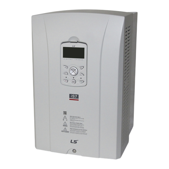
Page 8: Part Names
Part Names The illustration below displays part names. Details may vary between product groups. 0.75~75kW(3-Phase) Keypad Front cover Remove it when wiring Volt for front cover to fix Wiring bracket Ground terminal Cooling FAN Keypad connection Communication Option connection Encoder option PLC, Extention I/O, Communication Option connection... - Page 9 90~375kW(3-Phase) SCR Snubber FAN SMPS circuit Communication MAIN SMPS Option circuit Encoder Option PLC, Extention I/O etc option Keypad connection Shield plate I/O board and terminal Power Busbar(R/S/T, U/V/W, P/N) Upper front cover Keypad Volt for upper front Volt for upper front cover(right) cover(left side) Volt for lower front...
-
Page 10: Block Diagram
Block Diagram Name Description 3-phase AC line power supply to the Line power input adjustable frequency drive The rectifier bridge converts the AC input Rectifier to DC current to supply inverter power P1(+), P2(+) DC reactor wiring connection. Charging Restrict inrush current when power is resistor turned on. -
Page 11: Installation Instruction
2 Installation Instruction Installation Considerations Inverters are composed of various precision, electronic devices, and therefore the installation environment can significantly impact the lifespan and reliability of the product. The table below details the ideal operation and installation conditions for the inverter. Items Description - CT (Heavy Duty) load : - 10 ~ 50... -
Page 12: Selecting And Preparing A Site For Installation
Selecting and Preparing a Site for Installation Be careful so that the plastic parts of the inverter may not be damaged. Do not move the product holding the cover only. Do not install the product where there is vibration, a press or cart.. Life of the inverter greatly influenced by the surrounding temperatures, make sure that the surrounding temperature does not exceed the permitted temperature (-10 ~ 50 C). - Page 13 Install the inverter on an inflammable surface because its temperature rises high during operation. Sufficient space is required to prevent heat saturation because the inverter emits heat.
- Page 14 Remark Over 50cm, B : over 20cm is necessary when you install an inverter above 30kW Caution Avoid direct rays of light or a warm and humid place. Install the inverter in a closed panel or clean place free from foreign substances such as oil mist and fiber dust.
-
Page 15: Mounting
Mounting Mount the inverter on a wall or inside a panel following the procedures provided below. Before installation, ensure that there is sufficient space to meet the clearance specifications, and that there are no obstacles impeding the cooling fan’s air flow. Use a level to draw a horizontal line on the mounting surface, and then carefully mark the fixing points. - Page 16 Install the two lower mounting bolts. Ensure that the inverter is placed flat on the mounting surface, and that the installation surface can securely support the weight of the inverter. Note The quantity and dimensions of the mounting brackets vary based on frame size.
- Page 17 Do not transport the inverter by lifting with the inverter’s covers or plastic surfaces. The • inverter may tip over if covers break, causing injuries or damage to the product. Always support the inverter using the metal frames when moving it. Hi-capacity inverters are very heavy and bulky.
-
Page 18: Motor Connection
Motor Connection Connect motor by following procedure. Check cable specifications on 5.2 before connecting First, separate the keypad and the cable of keypad(❶) Ex) 0.75~7.5kW ❷ ❶ Loosen the bolt that secures the top cover. Then remove the cover by lifting it. (❷) Connect the cables to the power terminals. - Page 19 <Standard type> <Conduit type> Apply rated torques to the terminal screws. Loose screws may cause short circuits and • malfunctions. Tightening the screw too much may damage the terminals and cause short circuits and malfuctions. Use copper wires only with 600 V, 75 ℃...
- Page 20 ℃ rating for the control terminal wiring. Power supply wirings must be connected to the R, S, and T terminals. Connecting them to • the U, V, W terminals causes internal damages to the inverter. Motor should be connected to the U, V, and W Terminals. Arrangement of the phase sequence is not necessary.
- Page 21 Note Use STP (Shielded Twisted Pair) cables to connect a remotely located motor with the • inverter. Do not use 3 core cables. Make sure that the total cable length does not exceed 492 ft (150 m). For inverters < = 3.7 •...
-
Page 22: Ac Input Connection
AC Input Connection Connect AC Input power by following procedure. Check cable specifications on 5.2 before connecting. Connect 3 Phase AC input cable to R,S,T Do not activate the EMC filter if the inverter uses a power source with an asymmetrical grounding structure, for example a grounded delta connection. - Page 23 <Conduit type> Power supply cables must be connected to the R, S, and T terminals. Connecting power • cables to other terminals will damage the inverter. Use insulated ring lugs when connecting cables to R/S/T and U/V/W terminals. • The inverter’s power terminal connections can cause harmonics that may interfere with •...
-
Page 24: Grounding
Grounding Remove the terminal cover(s) and cable guide. Then follow the instructions below to install the ground connection for the inverter. Locate the ground terminal and connect an appropriately rated ground cable to the terminals. 0.75–7.5 kW (3-Phase) 11–75 kW (3-Phase) - Page 25 IS7 0.75–22 kW (3 phase) inverters have EMC filters built-in and activated as a factory default design. An EMC filter prevents electromagnetic interference by reducing radio emissions from the inverter. EMC filter use is not always recommended, as it increases leakage current. If an inverter uses a power source with an asymmetrical grounding connection, the EMC filter must be turned off.
- Page 26 Built-in EMC Filter The product which has a built-in EMC filter is efficient for reducing conductive and radiated noise from the input part of inverter. Turns On the On/Off switch of EMC filter to perform the EMI function if you are select the product which has a built-in EMC filter. (However, when unable to use EMC filter or due to the asymmetric structure of the ground to use, EMC filter of on/off swich is set to off 1) How to set EMC Filter functions (Less than 7.5kW Products)
- Page 27 3) How to set EMC Filter functions (11~22kW Products) EMC filter ON/OFF set terminal is located in lower part of the 11~22KW Terminal as shown figure below. Initial set isON. When the green wire is connected in upper metal connection terminal, EMC filter is ON and EMC filter is OFF if it is connected in insulated connection terminal.
-
Page 28: Control Wiring
Control Wiring The illustrations below show the detailed layout of control wiring terminals and control board switches. 2.7.1 Control terminal line diagram (Basic I/O terminal block, below 22kW products) NPN(Sink) /PNP(Source) TR set terminal Set terminal I/PTC Set terminal 2.7.2 Control terminal line diagram (Insulated I/O terminal block, above 30kW products) TR set terminal NPN(Sink) /PNP(Source) - Page 29 1)how to set NPN (Sink)/PNP (Source) iS7 serves 2 sequence input terminals of control circuit: NPN mode (Sink mode) and PNP mode(Source mode). It is possible to change the logic of input terminal with NPN mode (Sink mode) and PNP mode (Source mode) by using NPN (Sink)/PNP (Source) set terminal.
- Page 31 Control circuit Terminal Labels and Descriptions Type Label Name Description Multi-function P1~P Contact Available by defining as multi-function input input1~8 point start Common terminal of the contact point input Sequence function terminal common selectio (note: In case of Basic I/O, common terminal is terminal different from the 5G common terminal) Frequency...
- Page 32 Multi-function terminal DC 26V, below 100mA (open collector) Common terminal for External power supply common earth terminal of open the open collector collector Exterior 24V Maximum output current: 150mA power Protection function is activated to break output. (below AC 250V 5A, DC 30V 5A) Contact Point Fault signal...
- Page 33 Note While making wiring connections at the control terminals ensure that the total cable length • does not exceed 165 ft (50 m). Ensure that the length of any safety related wiring does not exceed 100 ft (30 m). • Ensure that the cable length between the keypad and the inverter does not exceed 10 ft •...
- Page 34 Post-Installation Checklist After completing the installation, check the items in the following table to make sure that the inverter has been safely and correctly installed. Items Check Point Result Is the installation location appropriate? Does the environment meet the inverter’s operating conditions? Installation Location/Power...
- Page 35 Items Check Point Result Is the shielding of the STP wiring properly grounded? If 3-wire operation is required, are the multi-function input terminals defined prior to the installation of the control wiring connections? Are the control cables properly wired? Are the control terminal screws tightened to their specified torques? Is the total cable length of all control wiring <...
-
Page 36: Start-Up Procedure
3 Start-Up Procedure Safety Instructions for Start-Up Before applying power See if cover is closed in appropriate posion. Check all cable connection is tightened with the right thickness and enough torque. Ensure the input power is turned OFF. Check R, S, T input power cable’s voltage. No voltage should be shown between each phase and ground. -
Page 37: About The Keypad
About the Keypad The keypad is composed of two main components – the display and the operation (input) keys. Refer to the following illustration to identify part names and functions. LCD Display REV mode REV mode LED indicator LED indicator STOP/RESET mode LED indicator... -
Page 38: Operation Keys
3.2.1 Operation Keys The following table lists the names and functions of the keypad’s operation keys. Name Description [MODE] Key Used to switch between modes. MODE [PROG / Ent] PROG Used to select, confirm, or save a parameter value. /ENT [Up] key Switch between codes or increase or decrease parameter [Down] key... - Page 39 3.2.2 About the Display Monitor mode display (1) Monitor Mode Multi-function Key Operating/Frequency command Inverter Operating Status Mode Display Status Display Item MON T/K N STP 0.00Hz Monitor Mode Display Item 1 Monitor Mode Monitor Mode Display Item 2 Cursor Monitor Mode Display Item 3 (2) Parameter change display Inverter Operating Status...
- Page 40 4) Display Item List (1) Mode Display Items : see “Mode shift”. (2) Group Display Items : see “Group shift”. (3) Operation Command/Frequency Command Display Items (Type of Sequence and number of steps are displayed during auto sequence operation) (4) Monitor Display Items Function Display Description...
- Page 41 Function Display Description Internal 485 frequency command 1~9 A~F Sequential frequency command JOG Key Used for shift to Keypad JOG mode Multi Local/Remote Used to select local or remote operation Function Key Used to register parameters as a user group in Setting User Group the parameter mode or delete parameters in...
-
Page 42: Display Modes
3.2.3 Display Modes SV-iS7 series inverter parameters consist of the following 5 modes. Each mode has its own function items suitable for the desired properties. The parameter mode displays the functions necessary for inverter operation in groups. Config Trip User&Macro... - Page 43 Mode Display Description Displays information on the operating status of the inverter. Monitor mode Can monitor frequency setting, operating frequency display, output current and voltage, etc. Used to set functions necessary for operation. Divided into a Parameter total of 12 groups, each suited to the level of the functional mode requirement and objective.
- Page 44 Macro group groups displayed in MC1 or MC2 are shown. You can select them in CNF Mode. For more details, see 8-48 page, 8.1.31 Addition to Macro Group in the detailed user manual, available from LSIS website.
-
Page 45: Mode Shift
3.2.4 Mode shift Monitor Config Parameter Trip User&Macro 1) Mode Shift at the time of delivery You can change the display as follows if you shift modes by using the mode key. The User/Macro Mode and Trip Mode are not displayed at the time of the product being delivered. - Page 46 - You have now shifted to Config Mode. - Press Mode key once. - You now route back to Monitor Mode. 2) Mode Shift with User/Macro Mode and Trip Mode If the user registers the user code or sets the macro function using the multi-function key, the User/Macro Mode will be displayed unlike the mode shift at the time of the product delivery.
-
Page 47: Group Shift
- You have shifted to Trip Mode. - Press Mode key once. - You have shifted to Config Mode. - Press Mode key once. - You come back to Monitor Mode. 3.2.5 Group shift You can make inter-group shift by using Left/Right keys after shift to Parameter Mode or User/Macro Mode using the Mode key. - Page 48 1) Group Shift in Parameter Mode If you press Right key in the Parameter Mode, the display changes as follows. If you press Left key, the display order will be reversed. - Power on, a display emerges as shown on the left. The present mode is the monitor mode.
- Page 49 - The group changed in sequence, PRT is displayed. - Press Right Shift key once. - You come back to the Drive Group(DRV) of Parameter Group. 2) Group shift in User/Macro Mode To shift to User/Macro Mode, the user code should be registered or you select the macro function.
-
Page 50: Code(Function Item) Shift
- You have shifted to Macro Group(MC1). - Press Right key. - You come back to User Group(USR). 3.2.6 Code(Function Item) shift 1) Code shift in monitor mode If you press Up and Down keys where the cursor is, names of frequency and current, etc. will be displayed. - Page 51 - The cursor shifts to the second display item after the output current display is gone. - Press Down key. - The third display item displays the output voltage. - Do not press any key for about 2 seconds after shift. - The output voltage display gone, the cursor shifts to the third display item.
- Page 52 2) Code shift (function Items) in other modes and groups Using Up and Down keys: The following figures give an example of shifting the code by using Up and Down keys in DRV and BAS of Parameter Mode. Code shift in other modes are the same.
- Page 53 - Check that code number 00 is displayed in the initial display of DRV of PAR(Parameter Mode). - Press Program key(PROG). - The cursor flashes so that you can enter the code number as on the left. - Enter 9 using Up key and press PROG. - You shift to Control Mode of code number 9.
-
Page 54: Parameter Setting
3.2.7 Parameter setting 1) Parameter setting in monitor mode You can set some parameters including frequency in Monitor Mode. The following is an example of frequency setting. - Check whether the cursor is in frequency item and the 09 frequency setting method in DRV is keypad. - Press PROG. - Page 55 - This is the initial display of Parameter Mode. - Press Down key. - You have shifted to 01 frequency setting code. - Press PROG. - The cursor flashes so that you can enter the desired operating frequency. - If you want to set the frequency at 10Hz, move the cursor to the desired place using Left/Right keys.
-
Page 56: Operating Status Monitoring
3.2.8 Operating status monitoring 1) Using monitor mode Three items at a time can be displayed items in Monitor Mode. Some items including frequency can be edited. Displayed items can be selected by the user in Config Mode(CNF). - This is the initial display of Monitor Mode. - The frequency, current and voltage are set as the default monitor items at the time of product delivery. - Page 57 2) Possible items for monitoring Function Mode Code Setting Range Initial Value Display Anytime Para Frequency 0 : Frequency Monitor Line-1 Speed 0 : Frequency Monitor Line-2 Output Current 2 : Output Current Monitor Line-3 Output Voltage 3 : Output Voltage Output Power WHour Counter DCLink Voltage...
- Page 58 3) How to use status display The items displayed on the top right of the keypad are displayed in modes other than Monitor Mode as well. Thus if you register a variable you are interested in the display, you can monitor it at any time regardless of the mode shift or change. - This is the initial display of Monitor Mode.
-
Page 59: Failure Status Monitoring
3.2.9 Failure status monitoring 1) Failure during operation - In case of a failure during operation, the mode automatically shifts to Trip Mode and the type of the current failure is displayed. - If you press Down key, the output frequency, current and operating status are displayed relating to the time that the failure occurred. - Page 60 - The types of failures are displayed. - Press PROG. - The display mode before failure checking is restored.
- Page 61 3) Saving and monitoring of failure history Previous failures are saved in Trip Mode. Up to 5 failures can be saved. Failure history is saved not only by Reset but also in case of a low voltage failure due to being switched off.
-
Page 62: How To Initialize Parameters
3.2.10 How to initialize parameters You can initialize the parameter which was has been changed by the user to the initial state at the time of delivery. Not only the entire parameter but individual groups of the parameter mode can be selected and initialized. - Monitor Mode is displayed - Shift to CNF by using Mode key. -
Page 63: Easy Start
Easy Start Run Easy Start On to easily setup the basic motor parameters required to operate a motor in a batch. Easy Start shows up when on initial power is given. To see the easy start again, set CNF-61 (Easy Start On) to ‘1 (Yes)’ to activate the feature, initialize all parameters by setting CNF-40 (Parameter Init) to ‘1 (All Grp)’, and restart the inverter to activate Easy Start Parameter Setting... - Page 64 Verifying the Motor Rotation This chapter is about a procedure to check the motor direction. Follow the instructions below to protect the motor from rotating in the reverse direction. Ensure that the motor, system, and any attached equipment are ready for start. It is the •...
- Page 65 Check the parameter settings before running the inverter. Parameter settings may have to • be adjusted depending on the load. To avoid damaging the inverter, do not supply the inverter with an input voltage that • exceeds the rated voltage for the equipment. Before running the motor at maximum speed, confirm the motor’s rated capacity.
-
Page 66: Trial Run
Trial Run After the post-installation checklist has been completed, follow the instructions below to test the inverter. Turn on the power supply to the inverter. Ensure that the keypad display light is on. Select the command source. Set a frequency reference, and then check the following: If V1 is selected as the frequency reference source, does the reference change •... -
Page 67: Application Set-Up Examples
Application Set-up Examples 3.5.1 Terminal Block as a Command Input Device (Fwd/Rev run commands) Multi-function terminals can be selected as a command input device. -
Page 68: Setting A Frequency Reference Using Input Voltage(V1)
3.5.2 Setting a Frequency Reference using Input Voltage(V1) You can set and modify a frequency reference by setting voltage inputs when using the V1 terminal. -
Page 69: Setting A Reference Frequency Using Input Current (I1)
3.5.3 Setting a Reference Frequency using Input Current (I1) You can set and modify a frequency reference using input current at the I1 terminal. -
Page 70: Setting A Frequency Reference Via Rs-485 Communication
3.5.4 Setting a Frequency Reference via RS-485 Communication Control the inverter with upper-level controllers, such as PCs or PLCs, via RS-485 communication. Set the Frq (Frequency reference source) code (code 07) in the DRV group to 6 (Int 485) and use the RS-485 signal input terminals (S+/S-/SG) for communication. -
Page 71: Diagnostics And Troubleshooting
This chapter explains how to troubleshoot a problem when inverter protective functions, fault trips, warning signals, or faults occur. If the inverter does not work normally after following the suggested troubleshooting steps, please contact the LSIS customer service center. Trip and Warning When the inverter detects a fault, it stops the operation (trips) or sends out a warning signal. - Page 72 LCD Display Type Description Displayed when internal DC circuit voltage Over Voltage Latch exceeds the specified value. Displayed when internal DC circuit voltage is less Low Voltage Level than the specified value. Displayed when internal DC circuit voltage is less Low Voltage2 Latch than the specified value during inverter operation.
- Page 73 Protection Functions Using Abnormal Internal Circuit Conditions and External Signals LCD Display Type Description Fuse Open Latch A failure occurs when the inverter DC fuse responds to over current only above 30kW. Over Heat Latch A failure occurs when the temperature of the inverter cooling fan rises over the prescribed degree.
- Page 74 LCD Display Type Description the prescribed value after the external temperature sensor is connected to the terminal block. Operation resumes if PRT-34 is set at values other than 0. ParaWrite Trip Latch Trouble during parameter writing with the inverter’s main body from the keypad. Over Speed Trip Latch A failure occurs when the motor speed goes up...
-
Page 75: Warning Message
LCD Display Type Description Option Trip-1 Latch When the option gets out of the option slot No. 1 after it was inserted during power supply or when communication is not available with the inverter Option Trip-2 Latch When the option gets out of the option slot No. 2 after it was inserted during power supply or when communication is not available with the inverter Option Trip-3... -
Page 76: Troubleshooting Fault Trips
LCD Display Description Auto Tuning and no signal is input during the encoder test. Signals are released if ENC Tune is set among the functions of OUT31~33. Enc Dir Check An alarm is signified if No. 3 Enc Test is selected from BAS-20 Auto Tuning and the setting is wrongly changed between encoder phase A and B during the encoder test or the rotation direction is reverse. - Page 77 Type Cause Remedy The inverter load is greater than the Replace the inverter with a model rated capacity. that has increased capacity. Operate the inverter after the motor The inverter supplied an output while has stopped or use the speed search the motor was idling.
- Page 78 Check the input wiring. Open Replace the DC link capacitor. The DC link capacitor needs to be Contact the retailer or the LSIS replaced. customer service center. The load is greater than the rated motor Replace the motor and inverter with capacity.
-
Page 79: Troubleshooting Other Faults
Type Cause Remedy The motor is disconnected to the output Check the connection of wiring. No Motor of inverter. Check the value of parameter both Trip The current level of detection of Trip is BAS-13 (Rated current) and PRT-32 incorrect. (No Motor Level). - Page 80 Type Cause Remedy terminal is incorrect. circuit terminal. The input option for the frequency Check the input option for the command is incorrect. frequency command. The input voltage or current for the Check the input voltage or current frequency command is incorrect. for the frequency command.
- Page 81 Type Cause Remedy is too high. the motor. Use a motor that can withstand phase-to-phase voltages surges greater than the maximum surge voltage. The phase-to-phase voltage of the Only use motors suitable for motor is insufficient. apllications with inverters. Connect the AC reactor to the inverter output (set the carrier frequency to 3 kHz).
- Page 82 Type Cause Remedy Replace the motor and inverter with There is a high variance in load. models with increased capacity. Motor speed varies during The input voltage varies. Reduce input voltage variation. operation. Motor speed variations occur at a Adjust the output frequency to specific frequency.
- Page 83 Type Cause Remedy The motor Check the input voltage and vibrates balance the voltage. Phase-to-phase voltage of 3-phase severely and power source is not balanced. Check and test the motor’s does not rotate insulation. normally. Resonance occurs between the Slightly increase or decrease the motor's natural frequency and the carrier frequency.
-
Page 84: Troubleshooting Flow Chart
Troubleshooting Flow Chart This chapter explains how to troubleshoot a problem when inverter protective functions, fault trips, warning signals, or faults occur . Follow below procedures to troubleshoot each fault and warning. 1) Overload Fault... - Page 85 2) Overcurrent Fault...
- Page 86 3) Over Load Fault...
- Page 87 4) Over Voltage Fault...
- Page 88 5) Low Voltage Fault...
- Page 89 6) Ground Fault...
-
Page 90: How To Check Power Components
How to Check Power Components Before checking the power components, be sure to disconnect AC Input supply and wait until the Main Electrolytic Capacitors (DCP-DCN) is discharged. Turn the power off and disconnect RST/UVW wiring. • Determine whether inverter terminals ((R,S,T, U, V, W, P1 (or P2), N)) are energized •... - Page 91 Test polarity Test polarity Check Check Module Number value value DCP+ Closed Open Close DCP+ Open DCP+ Closed Open Diode Close DCP+ Open DCP+ Closed Open Close DCP+ Open Closed Open Close Open Closed Open IGBT Close Open Closed Open Close Open...
-
Page 92: Technical Specification
5 Technical Specification Input and Output Specifications Input voltage of 200V class (0.75~22kW) Type : SV xxx iS7 – 2x 0008 0015 0022 0037 0055 0075 0110 0150 0185 0220 [HP] Motor Applied [kW] 0.75 18.5 Rated 12.2 17.5 22.9 28.2 33.5 Capacity [kVA]... - Page 93 Input voltage of 200V class (30~75kW) Type : SV xxx iS7 – 2x 0300 0370 0450 0550 0750 [HP] Motor Applied [kW] Rated Capacity [kVA] Rated Current[A] 0 ~ 400 [Hz] Output Frequency (Sensorless-1:0~300Hz, Sensorless-2,Vector:0.1~120Hz) Output Voltage 3-phase 200 ~ 230V Available 3-phase 200 ~ 230 VAC (-15%~+10%) Voltage [V]...
- Page 94 Input voltage of 400V class (0.75~22kW) Type : SV xxx iS7 – 0008 0015 0022 0037 0055 0075 0110 0150 0185 0220 [HP] Motor Applied [kW] 0.75 18.5 Rated 12.2 18.3 22.9 29.7 34.3 Capacity [kVA] Rated Current[A] 0 ~ 400 [Hz] Output Frequency (Sensorless-1: 0~300Hz, Sensorless-2, Vector: 0.1~120Hz)
- Page 95 Input voltage of 400V class (30~160kW) Type : SV xxx iS7 – 0370 0450 0550 0750 0900 1100 1320 1600 [HP] Motor Applied [kW] Rated Capacity [kVA] Rated Current[A] 0 ~ 400 [Hz] Output Frequency (Sensorless-1: 0~300Hz, Sensorless-2, Vector: 0~120Hz) Output Voltage 3-phase 380 ~ 480V Available...
- Page 96 Input voltage of 400V class (185~375kW) Type : SV xxx iS7 – 4x 1850 2200 2800 3150 3750 [HP] Motor Applied [kW] Rated Capacity [kVA] Rated Current[A] 0 ~ 400 [Hz] Output Frequency (Sensorless-1:0~300Hz, Sensorless-2,Vector:0~120Hz) Output Voltage [V] 3-phase 380 ~ 480V Available Voltage [V] 3-phase 380 ~ 480 VAC (-15%, +10%) Input Frequency 50 ~ 60 [Hz] (±5%)
-
Page 97: Cable Selection
Cable Selection When you install power and signal cables in the terminal blocks, only use cables that meet the required specification for the safe and reliable operation of the product. Refer to the following information to assist you with cable selection. Wherever possible use cables with the largest cross-sectional area for mains power wiring, •... - Page 98 Cable Inverter applied mm² R,S,T U,V,W R,S,T U,V,W 0.75 kW 1.5 kW 2.2 kW 3.7 kW 5.5 kW 7.5 kW 11 kW 200V 15 kW 18.5 kW 22 kW 30 kW 37 kW 45 kW 55 kW 75 kW 0.75~1.5kW 2.2 kW 3.7 kW 5.5 kW...
- Page 99 90 kW 110 kW 132 kW 160 kW 185 kW 220 kW 280 kW 315 kW 2x200 2x200 2x400 2x400 375 kW 2x250 2x250 2x500 2x500 Signal (Control) Cable Specifications Wire thickness Terminals P1–P7/CM/VR/V1/I2/24 0.33–1.25 16–22 AO1/AO2/CM/Q1/EG 0.33–2.0 14–22 A1/B1/C1/A2/C2/A3/C3/A4/C4/A5/C5 0.33–2.0 14–22 S+,S-,SG...
-
Page 100: Product Specification Details
Product Specification Details 1) Control V/F control, V/F PG, slip compensation, sensorless vector-1, sensorless vector-2, Control Method vector control Digital command : 0.01Hz Frequency Setting Resolving Power Analog command : 0.06Hz (maximum frequency : 60Hz) Digital command operation : 0.01% of the maximum frequency Frequency Degree Analog command operation : 0.1% of the maximum frequency V/F Pattern... - Page 101 2) Operation Selectable among keypad/terminal block/communication Operating Method operation Analog: 0 ~ 10[V], -10 ~ 10[V], 0 ~ 20[mA] Frequency Setting Digital: keypad PID control, up-down operation, 3-wire operation, DC break, Frequency limit, Frequency jump, Second function, Slip compensation, Reverse rotation prevention, Auto restarting, Operating Function Inverter By-pass, Auto tuning Flying Start, Energy buffering, Power breaking, Flux breaking, Leakage current reduction,...
- Page 102 3) Protective Function over voltage, low voltage, over current, earth current detection, inverter overheat, motor overheating, output imaging, overload Trip protection, communication error, frequency command loss, hardware failure, cooling fan failure, pre-PID failure, no motor trip, external break trip. etc Stall prevention, overload, light load, encoder error, fan failure, Alarm keypad command loss, speed command loss.
-
Page 103: Terminal Screw Specifications
(Pollution degree 2 environment) 3) UL Enclosed type 1 with conduit box installed. Terminal Screw Specifications Input/Output Termianl Screw Specification Screw torque Terminal screw Inverter applied size (Kgf cm) 0.75 kW 7.1~12 1.5 kW 7.1~12 2.2 kW 7.1~12 3.7 kW 7.1~12 5.5 kW 7.1~12... - Page 104 11 kW 24.5~31.8 15 kW 24.5~31.8 18.5 kW 30.6~38.2 22 kW 30.6~38.2 30~37 kW 61.2~91.8 45 kW 61.2~91.8 55 kW 61.2~91.8 75 kW 61.2~91.8 90 kW 182.4~215.0 110 kW 182.4~215.0 132 kW 182.4~215.0 160 kW 182.4~215.0 185 kW 182.4~215.0 220 kW 182.4~215.0 280 kW 182.4~215.0...
-
Page 105: External Dimensions (Ul Enclosed Type1, Ip21 Type)
External Dimensions (UL Enclosed Type1, IP21 Type) 1) SV0008-0037iS7 (200V/400V) mm(inches) Inverter capacity SV0008~0037 150(5.90) 127(5.00) 284(11.18) 257(10.11) 18(0.70) 200(7.87) 5(0.19) 5(0.19) iS7 - 2/4... - Page 106 2) SV0055-0075iS7 (200V/400V) mm(inches) Inverter capacity SV0055~0075 200(7.87) 176(6.92) 355(13.97) 327(12.87) 19(0.74) 225(8.85) 5(0.19) 5(0.19) iS7 - 2/4...
- Page 107 3) SV0110-0150iS7 (200V/400V) mm(inches) Inverter capacity SV0110~0150 250(9.84) 214.6(8.44) 385(15.15) 355(13.97) 23.6(0.92) 284(11.18) 6.5(0.25) 6.5(0.25) iS7- 2/4...
- Page 108 4) SV0185-0220iS7 (200V/400V) mm ( inches ) Inverter capacity SV0185~0220 280(11.02) 243.5(9.58) 461.6(18.17) 445(17.51) 10.1(0.39) 298(11.73) 6.5(0.25) 6.5(0.25) iS7- 2/4...
- Page 109 5) SV0300-iS7 (200V, IP00 Type) mm ( inches ) Inverter W2/W capacity SV0300 265.2 iS7-2 (11.81) (7.48) (22.44) (21.73) (0.39) (10.44) (0.39) (0.39)
- Page 110 6) SV0370-0450iS7 (200V, IP00 Type) mm ( inches ) Inverter W2/W3 capacity SV0370~04 281.2 (14.56) (10.63) (24.8) (23.97) (0.43) (11.07) (0.39) (0.39) iS7-2...
- Page 111 7) SV0300-0450iS7 (400V) mm ( inches ) Inverter capacity DCR Type 303.2 303.2 (11.93) (11.93) SV0300~0450 300.1 242.8 594.1 24.1 iS7-4 (11.81) (9.55) (23.38) (22.12) (0.94) (0.39) (0.39) Non-DCR Type 271.2 271.2 (10.67) (10.67)
- Page 112 8) SV0550-0750iS7 (200V, IP00 Type) mm(inches) Inverter W2/W3 capacity SV0550~0750 723.5 15.5 355.6 iS7-2 (18.3) (15.0) (29.52) (28.48) (0.61) (14.0) (0.43) (0.43)
- Page 113 9) SV0550-0750iS7 (400V) mm ( inches ) Inverter capacity DCR Type 373.3 211.5 SV0550~075 (14.69) (8.32) 370.1 312.8 663.5 631.4 24.1 (14.57) (12.31) (26.12) (24.85) (0.94) (0.39) (0.39) Non-DCR Type iS7-4 312.4 150.6 (12.29) (5.92)
- Page 114 10) SV0900-1100iS7 (400V, IP00 Type) mm ( inches ) Inverter capacity SV0900~1 783.5 15.5 422.6 (20.07) (15.0) (13.77) (30.84) (29.88) (0.61) (16.63) (0.43) (0.43) iS7-4...
- Page 115 11) SV1320-1600iS7 (400V, IP00 Type) mm ( inches ) Inverter capacity SV1320~1600 15.5 422.6 iS7-4 (20.07) (15.0) (13.77) (33.89) (32.93) (0.61) (16.63) (0.43) (0.43)
- Page 116 12) SV1850-2200iS7 (400V, IP00 Type) mm ( inches ) Inverter capacity SV1850/ 1078 1043.5 25.5 2200iS7-4 (27.16) (22.87) (20.79) (42.44) (41.08) (1.00) (17.72) (0.55) (0.59)
- Page 117 13) SV2800iS7 (400V, IP00 Type) mm ( inches ) Inverter capacity 1138 1110 SV2800iS7-4 (30.35) (19.69) (19.69) (44.80) (43.70) (0.59) (17.32) (0.51) (0.51)
- Page 118 14) SV3150-3750iS7 (400V, IP00 Type) mm ( inches ) Inverter capacity SV3150/ 1302.5 1271.5 3750iS7-4 (36.30) (22.83) (22.83) (51.28) (50.06) (0.59) (19.49) (0.55) (0.55)
-
Page 119: External Dimension (Ul Enclosed Type12, Ip54 Type)
External dimension (UL Enclosed Type12, IP54 Type) 1) SV0008-0037iS7 (200V/400V) mm ( inches ) Inverter capacity SV0008~0037 204.2 95.1 iS7-2/4 (8.03) (5.0) (16.49) (10.11) (3.74) (8.18) (0.19) (0.19) - Page 120 2) SV0055-0075iS7 (200V/400V) mm ( inches ) Inverter capacity 460.6 88.1 232.3 SV0055~0075 (10.0) (6.92) (18.13) (12.87) (3.46) (9.14) (0.19) (0.19) iS7- 2/4...
- Page 121 3) SV0110-0150iS7 (200V/400V) mm ( inches ) Inverter capacity SV0110~0150 313.1 214.6 590.8 101.7 294.4 iS7-2/4 (12.32) (8.44) (23.25) (13.97) (4.0) (11.59) (0.25) (0.25)
- Page 122 4) SV0185-0220iS7 (200V/400V) mm ( inches ) Inverter capacity SV0185~0220 343.2 243.5 750.8 91.6 315.5 iS7-2/4 (13.51) (9.58) (29.55) (17.51) (3.60) (12.42) (0.25) (0.25)
-
Page 123: Peripheral Devices
Peripheral Devices Compatible Circuit Breaker, Leakage Breaker and Magnetic Contactor Models (manufactured by LSIS) C i r c u i t B r e a k e r L e a k a g e M a g n e t i c... - Page 124 Maximum allowed prospective short-circuit current at the input power connection is defined in IEC 60439-1 as 100 kA. SV-IS7 is suitable for use in a circuit capable of delivering not more than 100kA RMS at the drive’s maximum rated voltage, depending on the selected MCCB.
-
Page 125: Reactors, Braking Resistor And Fuse Specifications
Reactors, Braking Resistor and Fuse Specifications (1) If you apply the recommended reactor, More than 85% power factor and THD 40% less operation is possible in generally power environment. However, the condition is based on the rated load. Improvement in the case of light load is reduced. (2) During operation, the input power factor and harmonic wave is affected by the impedance of the line Therefore, even applying the reactor, the input power factor and THD improvement can be... - Page 126 3150iS7-4 0.076 3750iS7-4 0.064 1195 Specifications of the AC reactor Specifications of the AC Specifications of the AC reactor reactor Capacity Capacity Heavy Duty Normal Duty Heavy Duty Normal Duty of inverter of inverter 0008iS7-2 2.13 1.20 0008iS7-4 8.63 4.81 0015iS7-2 1.20 0.88...
-
Page 127: Braking Resistor And Fuse Specifications
Braking Resistor and Fuse Specifications Braking Resistor Fuse Product (kW) Rated Capacity Current Voltage Resistor ( ) 0.75 1200 2400 3-Phase 2400 200 V 18.5 3600 3600 5000 7000 10000 15000 20000 0.75 1000 3-Phase 1200 400 V 2000 2400 18.5 3600 3600... - Page 128 Product (kW) Braking Resistor Fuse 5000 10000 10000 10000 15000 17000 20000 500V 25000 30000 30000 40000 1000 60000 1200 60000 1400 The standard for braking torque is 150% and the working rate (%ED) is 5%. If the working rate is 10%, the rated capacity for braking resistance must be calculated at twice the standard.
-
Page 129: Warranty
Warranty Service Information During the product warranty period, warranty service (free of charge) is provided for product malfunctions caused under normal operating conditions. For warranty service, contact an official LSIS agent or service center. - Page 130 • acts of nature (fire, flood, earthquake, gas accidents etc.) • modifications or repair by unauthorized persons • missing authentic LSIS rating plates • expired warranty period • Visit Our Website for detailed service information.
-
Page 131: Appendix
7 Appendix UL mark The UL mark applies to products in the United States and Canada. This mark indicates that UL has tested and evaluated the products and determined that the products satisfy the UL standards for product safety. If a product received UL certification, this means that all components inside the product had been certified for UL standards as well.
Need help?
Do you have a question about the SV-IS7 Series and is the answer not in the manual?
Questions and answers