
Related Manuals for LSIS Starvert iG5A Series


Summary of Contents for LSIS Starvert iG5A Series
- Page 1 Compact & Powerful Drive 0.4~1.5kW 1phase 200~230Volts 0.4~22kW 3Phase 200~230Volts 0.4~22kW 3Phase 380~480Volts...
- Page 2 Drive StArvert iG5A LS Starvert iG5A is very competitive in its price and shows an upgraded functional strength. User-friendly interface, extended drive ranges up to 22kW, superb torque competence and small size of iG5A provides an optimum use environment. Standard compliance Compactness iG5A...
- Page 3 Compact & Powerful Drive iG5A C o n t e n t s Overview Model & Type Standard Specifications Wiring Terminal Configurations Keypad Features Parameter Setting Trial Run Dimensions Braking Resistors and Peripheral Devices Function List Protective Functions Fault Remedy Drive Starvert iG5A Series...
- Page 4 iG5A Powerful & Upgraded Performance iG5A provides sensorless vector control, PID control, and ground-fault protection through powerful built-in functions. Sensorless vector control Speed vs Torque Characteristics The built-in sensorless vector control provides the superb speed control and powerful high torque. Ground-fault protection during running The ground-fault protection of output terminal...
-
Page 5: Remote Control
Automatic list-up of trip record Language support (Korean, English, Chinese) remote Control Convenient remote control to modify operation status (Forward/Reverse operation, Frequency, etc) Easy parameter setting Available to control up to 31 Drives RS-485, Modbus communication Drive Starvert iG5A Series... - Page 6 iG5A User-friendly Interface & Easy Maintenance The parameter setting becomes easier by adopting the 4 directions key. And iG5A supports easy maintenance via diagnosis and fan changeable structure. Diagnosis of output module Through easy parameter setting, iG5A can diagnose the status of output module.
-
Page 7: Compact Size
CE and UL standards. PNP/NPN input Both PNP and NPN inputs become possible and these enable to use the outer power. To do so, users will be given wider choices of selecting the controller. Drive Starvert iG5A Series... -
Page 8: Model & Type
iG5A Model & Type Applicable motor ranges 1 Phase 200v 3 Phase 200v 3 Phase 400v 0.4kW ( 0.5HP ) Sv004iG5A-1 Sv004iG5A-2 Sv004iG5A-4 0.75kW ( 1HP ) Sv008iG5A-1 Sv008iG5A-2 Sv008iG5A-4 1.5kW ( 2HP ) Sv015iG5A-1 Sv015iG5A-2 Sv015iG5A-4 2.2kW ( 3HP ) Sv022iG5A-2 Sv022iG5A-4 3.7kW ( 5HP ) -
Page 9: Standard Specifications
4) Max. frequency setting range is extended to 300Hz when H40 (Control mode select) is set to 3 (Sensorless vector control). 5) Max. output voltage cannot be higher than the input voltage. It can be programmable below input voltage. 6) Self-Cooling Drive Starvert iG5A Series... - Page 10 iG5A Standard Specifications Control method V/F, Sensorless vector control Digital command: 0.01Hz Frequency setting resolution Analog command: 0.06Hz (Max. freq.: 60Hz) Digital command: 0.01% of Max. output frequency Frequency accuracy Analog command: 0.1% of Max. output frequency Control V/F pattern Linear, Squared, User V/F Overload capacity 150% per 1 min.
- Page 11 Multi-step freq. - Middle Multi-step freq. - High Multi-function open collector output Potentiometer (1kohm, 1/2W) MO Common 10V power supply for potentiometer Freq. Setting Voltage signal input: -10~10V Freq. Current signal input: 0~20mA RS-485 communication terminal Input signal common Drive Starvert iG5A Series...
- Page 12 iG5A Wiring 11.0~22.0kW DB resistor DC reactor (Optional) 3 phase AC input P1(+) B1 B2 N(-) (Rated input voltage) Ground 24V output Multi-function analog output FX (Forward run) signal: 0~10V RX (Reverse run) Input signal common BX (Emergency stop) RST (Trip reset) A contact output JOG (Jog operation) Input signal common...
-
Page 13: Specifications For Power Terminal Block Wiring
SV0075iG5A-2 32/28 SV0110iG5A-2 30.7/26.6 SV0150iG5A-2 30.7/26.6 SV0185iG5A-2 30.5/26.5 SV0220iG5A-2 30.5/26.5 SV0004iG5A-4 M3.5 10/8.7 SV0008iG5A-4 M3.5 10/8.7 SV0015iG5A-4 15/13 SV0022iG5A-4 15/13 SV0037iG5A-4 15/13 SV0040iG5A-4 15/13 SV0055iG5A-4 32/28 SV0075iG5A-4 32/28 SV0110iG5A-4 30.7/26.6 SV0150iG5A-4 30.7/26.6 SV0185iG5A-4 30.5/26.5 SV0220iG5A-4 30.5/26.5 Drive Starvert iG5A Series... -
Page 14: Terminal Configuration
iG5A Terminal Configuration Control terminal specifications MO MG Wire size (mm Terminal Description Screw size Torque (Nm) Specification Single wire Stranded P1~P8 Multi-function input T/M 1-8 M2.6 Common terminal M2.6 Output voltage: 12V Power supply for external M2.6 Max. output current: 100mA potentiometer Potentiometer: 1~5kohm Max. -
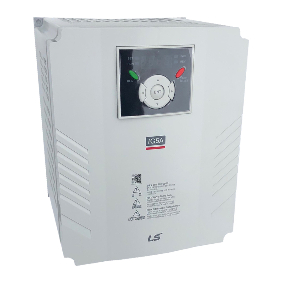
Page 15: Keypad Features
Lit during forward run Reverse run Lit during reverse run Run key Lit during operation Setting Lit during parameter setting 1) 4 LEDs above are set to blink when a fault occurs. Dimensions STOP 2-Φ4.5 RESET 13.9 23.1 Drive Starvert iG5A Series... -
Page 16: Moving To Other Groups
iG5A Moving to Other Groups Parameter groups There are 4 different parameter groups in iG5A series as shown below. Parameter group Description Drive group Basic parameters necessary for the drive to run. Parameters such as Target frequency, Accel/Decel time settable. Function group 1 Basic function parameters to adjust output frequency and voltage. - Page 17 •Keep pressing the Up (▲) key until the last code appears. •The last code in Drive group “drC” is displayed. •Press the Up (▲) key again. •Return to the first code of Drive group. •Use Down (▼) key for the opposite order. Drive Starvert iG5A Series...
-
Page 18: Trial Run
iG5A Trial Run Multi-step operation + run/Stop via FX/rX + Max. frequency change Operation condition Operation command: Frequency command: Max. frequency change: Run/Stop via FX/RX Multi-step operation [Low (20), Middle (30), High (80)] From 60Hz to 80Hz Wiring P1 (Forward) P2 (Reverse) 3 phase AC input... - Page 19 (DRV group) 10sec (Decel) 20sec (Decel) Set Decel time to 20sec in dEC. Forward run The default is FX. This value may change (P1: FX) Reverse run The default is RX. This value may change. (P2: RX) Drive Starvert iG5A Series...
- Page 20 iG5A Dimensions Sv004iG5A-2 / Sv008iG5A-2, Sv004iG5A-4 / Sv008iG5A-4 Φ mm (inches) Drive model (kW) W (mm) W1 (mm) H (mm) H1 (mm) D (mm) A (mm) B (mm) (kg) Φ SV004IG5A-2 65.5 0.76 SV008IG5A-2 0.75 65.5 0.77 SV004IG5A-4 65.5 0.76 SV008IG5A-4 0.75 65.5...
- Page 21 Sv055iG5A-2 / Sv075iG5A-2, Sv055iG5A-4 / Sv075iG5A-4 Φ mm (inches) Drive model (kW) W (mm) W1 (mm) H (mm) H1 (mm) D (mm) A (mm) B (mm) (kg) Φ SV055IG5A-2 3.66 SV075IG5A-2 3.66 SV055IG5A-4 3.66 SV075IG5A-4 3.66 Drive Starvert iG5A Series...
- Page 22 iG5A Dimensions Sv110iG5A-2 / Sv150iG5A-2 / Sv110iG5A-4 / Sv150iG5A-4 Φ mm (inches) Drive model (kW) W (mm) W1 (mm) H (mm) H1 (mm) D (mm) A (mm) B (mm) (kg) Φ SV110iG5A-2 11.0 189.5 9.00 SV150iG5A-2 15.0 189.5 9.00 SV110iG5A-4 11.0 189.5 9.00...
-
Page 23: Braking Resistors
Note) 1. The capacity of the MCCB should be 1.5 to 2 times the rated output current of the drive. Drive Starvert iG5A Series 2. Use an MCCB keep the drive from faulting out instead of using overheat protection (150% for one minute at the rated output current.) - Page 24 iG5A Braking Resistors and Peripheral Devices Fuses & AC reactors AC external fuse Model AC reactor DC reactor Voltage [V] Current [A] 004iG5A-1 10 A 600V 4.20 mH, 3.5 A 008iG5A-1 10 A 600V 2.13 mH, 5.7 A 015iG5A-1 15 A 600V 1.20 mH, 10 A 004iG5A-2...
-
Page 25: Function List
Displays DC link voltage inside the drive. link voltage] This parameter displays the item selected at H73- [Monitoring item select]. [User display A10B vOL Output voltage select] Output power Torque 1) This function can be available with iG5A Communication Option Module. Drive Starvert iG5A Series... -
Page 26: Function Group
iG5A Function List Drive Group Address for Parameter Min/Max Factory Adj. Description display communication name range defaults during run Displays the types of faults, frequency and operating status at A10C [Fault Display] the time of the fault Sets the direction of motor rotation when drv - [Drive mode] is set [Direction of to either 0 or 1. - Page 27 1) Only displayed when F 4 is set to 1 (DC brake to stop). 2) If H40 is set to 3 (Sensorless vector), Max. frequency is settable up to 300Hz. 3) Only displayed when F24 (Frequency high/low limit select) is set to 1. Drive Starvert iG5A Series...
- Page 28 iG5A Function List Function group 1 Address for Parameter Min/Max Factory Adj. Description display communication name range defaults during run {Linear} A21E [V/F pattern] 0 ~ 2 {Square} {User V/F} [User V/F 0 ~ 400 It is used only when V/F pattern is set to 2(User V/F) A21F 15.00 frequency 1]...
- Page 29 I(0~20mA) input draw run V1(-10~10V) input draw run A247 [Draw rate] 0~100[%] Sets rate of draw 0.00 1) It is indicated when setting bit 2 of F59 as 1 2) Set F63 to 1 to display this parameter. Drive Starvert iG5A Series...
- Page 30 iG5A Function List Function group 2 Address for Parameter Min/Max Factory Adj. Description display communication name range defaults during run Sets the code number to jump. A300 [Jump code] 0~95 A301 [Fault history 1] A302 [Fault history 2] Stores information on the types of faults, the frequency, the A303 [Fault history 3] current and the Accel/Decel condition at the time of fault.
- Page 31 This setting is displayed via rPM in drive group. motor poles] 1) Normal acceleration has first priority. Even though #4 is selected along with other bits, Drive performs Speed search #4. 2) H30 is preset based on drive rating. Drive Starvert iG5A Series...
- Page 32 iG5A Function List Function group 2 Address for Parameter Min/Max Factory Adj. Description display communication name range defaults during run rpm X p fs = fr - [Rated slip 0 ~ 10 Where, fs = Rated slip frequency A320 2.33 frequency] [Hz] fr = Rated frequency...
- Page 33 1) Set H49 to 1 (PID control) to display this parameter. 2) Set H49 as a 1 Drive Starvert iG5A Series 3): it is indicated when setting H64(KEB drive select) as a 1 (KEB does not operate when cut power after loading ting input (about 10%).
- Page 34 iG5A Function List Function group 2 Address for Parameter Min/Max Factory Adj. Description display communication name range defaults during run Settable unit: 0.01 second. [Accel/Decel Settable unit: 0.1 second. A347 0 ~ 2 time scale] Settable unit: 1 second. This parameter selects the parameter to be displayed on the keypad when the input power is first applied.
- Page 35 0 ~ FFFF UL (Unlock) Parameter change enable L (Lock) Parameter change disable 1) It is indicated when choosing I17~I24 as a 12 (2nd motor select). 2) H91,H92 parameters are displayed when Remote option is installed. Drive Starvert iG5A Series...
-
Page 36: Input/Output Group
iG5A Function List Input/output group Address for Parameter Min/Max Factory Adj. Description display communication name range defaults during run A400 [Jump code] 0 ~ 87 Sets the code number to jump. [NV input 0 ~ -10 Sets the minimum voltage of the NV (-10V~0V) input. A402 0.00 Min voltage]... - Page 37 It cannot be set greater than F21 - [Max frequency]. [Multi-Step [Hz] A420 20.00 frequency 6] [Multi-Step A421 15.00 frequency 7] [Multi-Accel A422 time 1] [Multi-Decel 0~ 6000 A423 time 1] [sec] [Multi-Accel A424 time 2] Drive Starvert iG5A Series...
- Page 38 iG5A Function List Input/output group Address for Parameter Min/Max Factory Adj. Description display communication name range defaults during run [Multi-Decel A425 time 2] [Multi-Accel A426 time 3] [Multi-Decel A427 time 3] [Multi-Accel A428 time 4] [Multi-Decel A429 time 4] [Multi-Accel 0~ 6000 A42A time 5]...
- Page 39 It is used when freq command is given via V1 /I terminal or [Drive mode RS485. select after loss Continuous operation at the frequency before its A43E 0 ~ 2 of frequency command is lost. command] Free Run stop (Output cut-off) Decel to stop Drive Starvert iG5A Series...
- Page 40 iG5A Function List Input/output group Address for Parameter Min/Max Factory Adj. Description display communication name range defaults during run This is the time drive determines whether there is the input [Wait time after 0.1 ~ 120 frequency command or not. If there is no frequency command A43F loss of frequency [sec]...
- Page 41 Sets RX frequency to open the brake 1.00 frequency] [Hz] [Brake close 0~19 A456 Sets delay time to close the brake 1.00 delay time] [Brake close 0~400 A457 Sets frequency to close the brake 2.00 frequency [Hz] Drive Starvert iG5A Series...
-
Page 42: Protective Functions
iG5A Protective Functions Keypad display Protective functions Descriptions The drive turns off its output when the output current of the drive flows more than 200% of the drive rated current. The drive turns off its output when a ground fault occurs and the ground fault current is more than the internal setting value of the drive. -
Page 43: Fault Remedy
→ Check for connection of communication line and communication error keypad and remote keypad. connector. - EEP: Parameter save error - HWT: Hardware fault → Contact your LSIS sales distributor. - Err: Communication Error - COM: Keypad error Drive Starvert iG5A Series... - Page 44 Do not disassemble or repair by yourself! Safety Instructions Any maintenance and inspection shall be performed by the personnel having expertise concerned. • www.lsis.com © 2005.5 LSIS Co.,Ltd. All rights reserved. ■ HEAD OFFICE Overseas Branches LS Tower, 127, LS-ro, Dongan-gu, Anyang-si, Gyeonggi-do, Korea LSIS Shanghai Office, China ●...
Need help?
Do you have a question about the Starvert iG5A Series and is the answer not in the manual?
Questions and answers