Advertisement
Quick Links
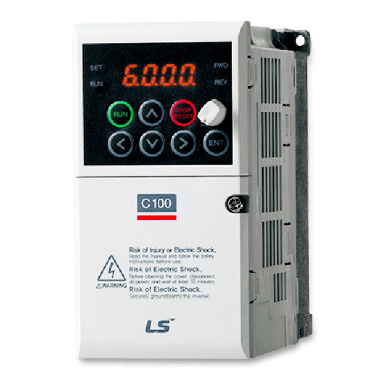
1. C100 Basic Setup Parameters
The basic drive and motor parameters are shown in Table 1. Set the parameters according to your application.
Table 1. C100 Basic Setup Parameters
7 Segment
Description
Group No
Drive 0.00 Command Freq
Drive ACC Acc Time
Drive
dEC Decel Time
Drive
drV
Run Command
Drive
Frq
Freq Command
F
39 Motor Voltage
F
67 Input Voltage (200V)
F
68 Input Voltage (400V)
H
30 Motor Capacity
H
31 Poles
H
32 Slip
H
33 Motor Rated Current
H
34 No Load Current
H
36 Motor Eff %
Note: Many applications will not require changes to the basic setup parameters from their default values.
1.1 C100 Recommended Additional Parameter Changes
The C100 has some default settings the user may want to change to obtain better protection of the drive/motor and
the application. These changes are recommended, but not needed for all applications.
Auto Reset:
Program H21 (Reset/Restart after a fault) to "1"
Program H26 (Number of Retries) to a number between 0 -10.
Start on Power Loss
Program H20 (Power on Start) to "1".
Phase Loss
Program H19 (Phase Loss) to the correct bit to the high state for output, input, or both phase loss
recognition.
This parameter is in the form of 2 bits. Left bit is 2 (Input), Right bit is bit 1 (Output). It is represented is in the form
of one section of the 7 segment display, ie.
Off state.
LSIS VFD Quick Start Guide
C100, S100, H100, and iS7
C100
Default
Set Options
0.00
0 - Max Freq
20
0 - 6000
30
1 - 6000
0: Keypad
1: Fx/Rx-1
1
Fx/Rx-1
2: Fx/Rx-2
3: Comm RS485
0: Keypad-1
1: Keypad-2
2: Panel Pot V2 (0-5V)
3: Terminal A1 (0-10V)
0
Keypad-1
4: Terminal A1 (4-20mA)
5: Panel Pot + Terminal A1 (4-20mA) Set J1 to I
6: Panel Pot + Terminal A1 (0-10V)
7: Comm RS485
8: Up/Down
Depends on drive
40 - 110%
220
170 - 240V
380
320 - 480V
Depends on drive
Depends on drive
4
2 - 12
Depends on drive
0 - 10 Hz
Depends on drive
Depends on drive
Depends on drive
0.0 - 1000A
72
70 - 100%
= low, low;
| |
Notes
Start/Stop FW or REV wired separate (P1 = FW, P2 = Rev)
2 Wire Start/Stop (P1 = FW, P2 = Rev)
Press ENTER to save values
Value Changes immediately
Set J1 to V
Set J1 to I
Set J1 to V
Set as a percentage from the default (220V & 380V)
If not given then: Rated Freq -((rpm x poles)/120)
| |
= High, High. High represents On state, Low represents
1
LSIS VFD Quick Start Guide
Rev G_10-2-2015
By Gary Baase
Advertisement

Summary of Contents for LSIS C100
- Page 1 Note: Many applications will not require changes to the basic setup parameters from their default values. 1.1 C100 Recommended Additional Parameter Changes The C100 has some default settings the user may want to change to obtain better protection of the drive/motor and the application. These changes are recommended, but not needed for all applications.
- Page 2 LSIS VFD Quick Start Guide C100, S100, H100, and iS7 2. S100/H100/iS7 Basic Setup Parameters The basic drive and motor parameters are shown in Table 2. Set the parameters according to your application. Table 2. iS7/H100/S100 Basic Setup Parameters S100/H100/iS7...
- Page 3 3. HP to kW Conversion Table Use the following conversion table to enter the motor HP. Select the closet size the drive allows in kW (motor power is in kW on most LSIS drives).. Table 3. HP to kW Conversion...


Need help?
Do you have a question about the C100 and is the answer not in the manual?
Questions and answers