Sign In
Upload
Manuals
Brands
LSIS Manuals
Inverter
SV-iS7 series
LSIS SV-iS7 series Manuals
Manuals and User Guides for LSIS SV-iS7 series. We have
10
LSIS SV-iS7 series manuals available for free PDF download: User Manual, Manual
LSIS SV-iS7 series User Manual (255 pages)
0.75-75kW [200W] 0.75-375kW [400V]
Brand:
LSIS
| Category:
Inverter
| Size: 13 MB
Table of Contents
Table of Contents
6
1 About the Product
12
Preparing for Installation and Operation
12
Identifying the Product
12
Checking the Product for Defects or Damage
14
Preparing the Product for Installation and Operation
14
Installing the Product
14
Connecting the Cables
14
Part Names
15
Interior and Exterior View (IP 21 Model Types Less than 22 Kw [200 V] / Less than 75 Kw [400 V])
15
Interior and Exterior View (IP 54 Model Types Less than 22 Kw [200/400 V])
16
Interior and Exterior View (Model Types 30 Kw and up [200 V] / 90 Kw and up [400 V])
17
2 Technical Specifications
18
Input and Output Specifications 200 V Class (0.75-22 Kw)
18
Input and Output Specifications 200 V Class (30-75 Kw)
19
Input and Output Specifications 400 V Class (0.75-22 Kw)
20
Input and Output Specifications 400 V Class (30-160 Kw)
21
Input and Output Specifications 400 V Class (185-375 Kw)
22
Product Specification Details
23
Control
23
Operation
23
Protection Function
25
Structure and Operating Environment Control
25
3 Installing the Inverter
27
Installation Considerations
27
Selecting and Preparing a Site for Installation
28
Exterior and Dimensions (UL Enclosed Type 1, IP21 Type)
32
Exterior and Dimensions (UL Enclosed Type 12, IP54 Type)
46
Frame Dimensions and Weight (UL Enclosed Type 1, IP 21 Type)
50
Frame Dimensions and Weight (UL Enclosed Type 12, IP54 Type)
52
Installation Procedures for UL Enclosed Type12 and IP54 Type Products
53
Disassembling the Keypad Cover and Keypad
53
Disassembling the IP54
54
Mounting the Inverter
55
Connecting the Power Cables
56
Reassembling the IP54 Front Cover and the Keypad
57
4 Connecting the Cables
59
Removing the Front Cover for Cable Connection
59
IP 21 Type Products
59
IP 54 Type Products
61
Kw, 400 V and 30-75 Kw, 200 V Products
62
Activating and Deactivating the Built-In EMC Filter
63
Up to 7.5 Kw Inverters
63
Kw Inverters
65
Precautions for Wiring the Inverter
67
Ground Connection
68
Terminal Wiring Diagram
69
Up to 7.5 Kw Inverters
69
Kw Inverters
69
Kw Inverters
70
Connecting Cables to the Power Terminal Block
71
22 Kw (200 V/400 V)
71
Kw (200 V/400 V)
72
Kw (400 V)
73
Kw (400 V)
74
Kw (200 V/400 V)
75
Specifications of the Power Terminal Block and Exterior Fuse
76
Cable Length between the Inverter and the Motor
77
Protective Measures for the Inverter and the Motor
78
Control Terminal Wiring for Is7 Inverters Rated for up to 22 Kw
79
NPN Mode (Sink)
80
PNP Mode (Source)
80
22 Kw (Basic I/O)
81
Control Terminal Wiring for Is7 Inverters Rated for 30 Kw or more
82
Terminal Inputs for Inverter Operation
83
Cable Specifications for Control Block Wiring
85
Setting the Built-In Surge Filter
86
Activating or Deactivating the Surge Filter
87
Is7 30-75KW (400 V) Inverters
87
Is7 90-375 Kw (400V) Inverters
87
Post-Installation Checklist
89
Test Run
90
Entering Easy Start Mode
90
Setting the Basic Parameters in Easy Start Mode
91
Checking the Inverter Operation
92
5 Using the Keypad
93
About the Keypad
93
Dimensions
93
Key Functions
94
Display Items
95
Display Item List
95
Menu Items
98
Parameter Mode
99
User & Macro Mode
100
Navigating Modes
101
Mode Navigation at the Factory Default
101
Mode Navigation with User/Macro Mode and Trip Mode
102
Navigating Modes and Parameters
104
Group Navigation in Parameter Mode
104
Group Shift in User & Macro Mode
106
Navigating through Codes (Function Items)
107
Code Navigation in Monitor Mode
107
Code Navigation (Function Items) in Other Modes and Groups
108
Code Navigation Using Jump Code
109
Setting Parameters
111
Parameter Settings in Monitor Mode
111
Parameter Settings in Other Modes and Groups
112
Monitoring Operating Status
113
Using Monitor Mode
113
Monitoring Items
114
Using the Status Display
115
Monitoring Faults
116
Faults During Inverter Operation
116
Multiple Faults at a Time During Inverter Operation
117
Saving and Monitoring the Fault Trip History
117
Initializing Parameters
119
6 Basic Functions
121
Setting Frequency References
121
Keypad as the Source (Keypad-1 Setting)
122
Keypad as the Source (Keypad-2 Setting)
122
V1 Terminal as the Source
122
Setting a Frequency Reference Using an I/O Expansion Module (Terminal V2/I2)
132
Setting a Frequency with Pulse Input (with an Optional Encoder Module)
134
Setting a Frequency Reference Via RS-485 Communication
136
Frequency Hold by Analog Input
137
Changing the Displayed Units (Hz↔Rpm)
138
Setting Multi-Step Frequency
138
Command Source Configuration
141
The Keypad as a Command Input Device
141
The Terminal Block as a Command Input Device (Fwd/Rev Run Commands)
142
The Terminal Block as a Command Input Device (Run and Rotation Direction Commands)
143
Communication as a Command Input Device
144
Forward or Reverse Run Prevention
144
Power-On Run
145
Setting Acceleration and Deceleration Times
146
Acc/Dec Time Based on Maximum Frequency
146
Acc/Dec Time Based on Operation Frequency
148
Multi-Step Acc/Dec Time Configuration
149
Configuring Acc/Dec Time Switch Frequency
150
Output Voltage Setting
152
7 Troubleshooting and Maintenance
153
Protection Functions
153
Protection from Output Current and Input Voltage
153
Abnormal Circuit Conditions and External Signals
154
Keypad and Optional Expansion Modules
156
Warning Messages
157
Troubleshooting Fault Trips
158
Replacing the Cooling Fan
161
Products Rated below 7.5 Kw
161
Products Rated at 11-15 Kw 200 V/400 V and 18.5-22 Kw 400 V
161
Products Rated at more than 30 Kw (200 V) / 90 Kw (400 V), and 18.5-22 Kw (200 V) / 30-75 Kw (200/400 V)
162
Daily and Regular Inspection Lists
163
8 Table of Functions
166
Parameter Mode - DRV Group (DRV)
166
Parameter Mode - Basic Function Group (BAS)
169
Parameter Mode - Expansion Function Group (PARADV)
173
Parameter Mode - Control Function Group (CON)
177
Parameter Mode - Input Terminal Block Function Group (IN)
183
Parameter Mode - Output Terminal Block Function Group (OUT)
187
Parameter Mode - Communication Function Group (COM)
191
Parameter Mode - Applied Function Group (APP)
194
Parameter Mode - Auto Sequence Operation Group (AUT)
197
Parameter Mode - Option Module Function Group (APO)
200
Parameter Mode - Protective Function Group (PRT)
203
Parameter Mode - 2Nd Motor Function Group (M2)
206
Trip Mode (TRP Current (or Last-X))
207
Config Mode (CNF)
207
User/Macro Mode - Draw Operation Function GroupMc1
210
User/Macro Mode - Traverse Operation Function Group (MC2)
211
9 Peripheral Devices
212
Wiring Switch, Electronic Contactor, and Reactor Specifications
213
Wiring Switch, Short Circuit Switch, and Electronic Contactor
213
Reactors
215
Dynamic Braking Unit (DBU) and Resistor
218
DB Unit Dimensions
222
Indicators on the DB Unit
228
DB Resistors
228
DB Resistor Dimensions
230
Keypad Extension Cable for Remote Control (Optional)
232
10 Safety Funtion STO(Safe Torque Off)
235
Safety Standard Product
235
About the Safety Function
235
Safety Function Wiring Diagram
236
Installing the Safety Board to 0.75-160 Kw Product
237
Installing the Safety Board to 185-375 Kw Product
237
Safety Function Terminal Description
238
Cable Specification for Signal Terminal Block Wiring
238
11 Marine Certification
239
DNV (Det Norske Veritas) Marine Certification Details
239
Bureau Veritas (Marine & Offshore Division) Marine Certification Details
239
ABS Marine Certification Details
239
Marine Certification Models for SV-Is7 Products
240
12 Using a Single Phase Power Source
242
Single Phase Rating
242
Power(Hp), Input Current and Output Current
243
Input Frequency and Voltage Tolerance
244
Wiring and Peripheral Device
245
Other Considerations
248
Product Warranty
249
Index
252
Advertisement
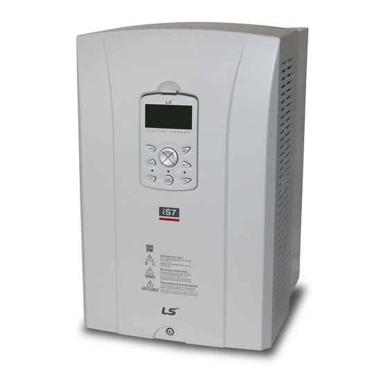
LSIS SV-iS7 series User Manual (201 pages)
SV-iS7 Series 0.75-75kW[200V] 0.75-375kW[400v]
Brand:
LSIS
| Category:
Inverter
| Size: 3 MB
Table of Contents
Safety Instructions
3
Caution for Use
5
Transportation and Installation
5
Wiring
6
Adjustment before Starting Trial Operation
7
How to Use
7
Countermeasure against Malfunction Troubles
8
Disposal
8
Maintenance, Inspection and Parts Replacement
8
Cleaning
9
General Instruction
9
Storage
9
Table of Contents
12
Check of Product
17
What You Should Know before Use
17
Chapter 3 Installation
18
Distribution
18
Parts
18
Preparation of Device and Parts for Operation
18
End Product (Less than 75 Kw)
19
Names and Uses of Parts
19
When the Front Cover Is Removed (Less than 75 Kw)
19
End Product (more than 90Kw)
20
When the Front Cover Is Removed (more than 90Kw)
20
Rated Input and Output: Input Voltage of 200V Class (0.75~22Kw)
21
Rated Input and Output: Input Voltage of 200V Class (30~75Kw)
21
Specifications
21
Rated Input and Output: Input Voltage of 400V Class (0.75~22Kw)
22
Rated Input and Output: Input Voltage of 400V Class (30~160Kw)
22
Control
23
Other Commons
23
Rated Input and Output: Input Voltage of 400V Class (185~375Kw)
23
Protective Function
25
Structure and Use Environment
25
Checking List
27
Electrical Installation Checking List
27
Mechanical Installation Checking List
27
Cautions before Installation
28
Exterior and Dimension
30
SV0055-0075Is7 (200V/400V)
31
SV0110-0150Is7 (200V/400V)
32
SV0185-0220Is7 (200V/400V)
33
SV0300-Is7 (200V, IP00 Type)
34
SV0370-0450Is7 (200V, IP00 Type)
35
SV0300-0450Is7 (400V)
36
SV0550-0750Is7 (200V, IP00 Type)
37
SV0550-0750Is7 (400V)
38
SV0900-1100Is7 (400V, IP00 Type)
39
SV1320-1600Is7 (400V, IP00 Type)
40
SV1850-2200Is7 (400V, IP00 TYPE)
41
Sv2800Is7 (400V, IP00 TYPE )
42
SV3150-3750Is7 (400V, IP00 TYPE )
43
External Dimension (UL Enclosed Type12, IP54 Type)
44
SV0008-0037Is7 (200V/400V)
44
Dimension and Weight of Frame (UL Enclosed Type 1, IP 21Type)
48
Dimension and Weight of Frame
50
(UL Enclosed Type12, IP54 Type)
50
How to Separate IP54 Front Cover
51
How to Separate IP54 Keypad Cover and Keypad
51
Installation Guide (UL Enclosed Type12, IP54 Type)
51
Mounting the Inverter
52
Power Cable Wiring
52
How to Attach the IP54 Front Cover
53
Chapter 4 Wiring
55
Wiring
55
How to Separate Front Cover When Wiring
57
How to Assemble Plug When Connecting Keypad
57
How to Separate Keypad
57
How to Separate Front Cover
58
(90~375 Kw 400V, 30~75Kw 200V)
59
Built-In EMC Filter
60
How to Remove EMC Filter ON/OFF Connector (Less than 7.5Kw Product)
60
How to Set EMC Filter Functions (Less than 7.5Kw Products)
60
Asymmetrical Ground Structure
61
How to Set EMC Filter Functions (11~22Kw Products)
61
Wiring Precaution
62
Grounding
62
Terminal Wiring Diagram (POWER Terminal Block)
63
Wiring of 11~22Kw Product
63
Wiring of 30~75Kw Product
63
Wiring of Inverter below 7.5Kw
63
Wiring of 185~220Kw Product
64
Wiring of 280~375Kw Product
64
Wiring of 90~160Kw Product
64
Built-In Dynamic Braking Unit Used
65
Optional Dynamic Braking Unit Used
65
Terminals of Main Circuit
65
Specifications of Power Terminal Block and Exterior Fuse
68
Control Terminal Line Diagram
70
How to Set NPN (Sink)/Pnp (Source)
70
NPN Mode (Sink Mode)
70
PNP Mode (Source Mode)
71
Control Circuit Terminal
75
Contact Point Start Function Selection
75
Specifications of Signal Terminal Block Distribution
76
Operation Checking
77
Easy Start Operation
77
Checking for Normal Working
78
Chapter 5 How to Use Keypad
79
Standard KEYPAD Appearance and Description (Graphic Keypad)
79
Dimensions
79
Key Functions
80
Composition of Display
81
Display Item List
81
Monitor Mode
81
Parameter Change Display
81
Monitor Display Items
82
Menu Composition
84
Mode Shift
87
Group Shift
88
Group Shift in Parameter Mode
88
Code (Function Item) Shift
89
Code Shift (Function Items) in Modes and Groups
89
Parameter Setting
90
Parameter Setting in Modes and Groups
90
Operating Status Monitoring
91
Using Monitor Mode
91
Possible to Monitoring Items
92
Failure Status Monitoring
93
Failure During Operation
93
Multiple Failures at a Time
93
Saving and Monitoring of Failure History
94
How to Initialize Parameter
95
How to Set Frequency (When You Want to Set Frequency)
97
Frequency Setting Using Keypad 1
97
Frequency Setting Using Keypad 2
97
Chapter 6 Basic Functions
97
Frequency Setting by Voltage Input (V1 Terminal) of the Terminal Block
98
Frequency Setting by Current Input into Terminal Block (I1 Terminal)
102
Frequency Command by Advanced I/O Option Card
103
Frequency Setting by Encoder Option Card
104
Frequency Setting by RS-485 Communication
105
Analog Command Frequency Fixation
106
Changing Frequency to Revolution
107
Sequential Frequency Setting
107
Operating Command Setting Method
108
Keypad Operating Command
109
Operating Command by RS-485 Communication
110
Prevention of Forward or Reverse Rotation
110
Run Immediately with Power on
110
Setting of Accelerating/Decelerating Time and Pattern
111
Setting of Accelerating/Decelerating Time on the Basis of the Maximum Frequency
111
Setting of Acc/Dec Time Based on Operating Frequency
112
Setting of Acc/Dec Time by Using Multi-Function Terminal Based on Operating Frequency
113
Acc/Dec Time Set by Setting the Acc/Dec Time of Switching Frequency
114
Motor Output Voltage Adjustment
115
Checking and Troubleshooting
117
Protection from Output Current and Input Voltage
117
Protective Functions
117
Protection by Internal Circuit Abnormality or External Signals
118
Protection by KEYPAD and Option
119
Alarm Functions
120
Troubleshooting
121
Replacement of Cooling Fan
124
Replacement Steps of Product of 11~15Kw 200V/400V, 18.5~22 Kw 400V
124
Replacement Steps of the Product below 7.5Kw
124
Checking Points
126
Daily and Regular Checkup List
126
Routine Checking
127
Regular Checking (1 Year Interval)
129
Regular Checking (2 Year Interval)
131
Parameter Mode – DRV Group
133
Table of Functions
133
Parameter Mode – Basic Function Group
135
Parameter Mode –Extended Function Group
138
Parameter Mode – Control Function Group
143
Parameter Mode – Input Terminal Block Function Group ( IN)
148
Parameter Mode – Output Terminal Block Function Group ( OUT)
152
Parameter Mode – Applied Function Group ( APP)
159
Parameter Mode – Auto Sequence Operation Group ( AUT)
162
Parameter Mode – Option Card Function Group ( APO)
166
Parameter Mode – Protective Function Group ( PRT)
168
Config Mode (CNF)
172
Trip Mode (TRP Current (or Last-X))
172
Composition of Peripheral Devices
177
Peripheral Devices
177
Specifications of Wiring Switch, Electronic Contactor and Reactor
178
Specifications of the DC Reactor
179
Specifications of the AC Reactor
180
Dynamic Breaking Unit (DBU) and Resistors
181
Dynamic Breaking Unit Type
181
Terminal Arrangement
181
DB Resistors
183
Option Type Dynamic Breaking Unit
183
Appearance and Size of Braking Resistor
184
IS7 Remote Cable Options
186
Keypad Bracket Drawings
186
Connection of Remote Cable
187
Functional Safety
189
Safety Function Description and Wiring Diagram
189
Safety Standard Product
189
0.75~160KW Product Installation
190
Example of Safety Input Wiring
190
185~375KW Product Installation
191
Description of Safety Function Terminal
191
Signal Terminal Block Wiring Standard
191
Classification Product
193
Classification Standard
193
Classification Standard Qcquisition
193
Ec Declaration of Conformity
195
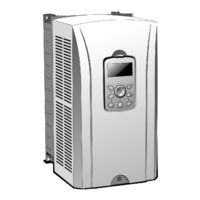
LSIS SV-iS7 series User Manual (252 pages)
AC Variable Speed Drive Web Control
Brand:
LSIS
| Category:
Controller
| Size: 4 MB
Table of Contents
About this Manual
3
Safety Precautions
4
Usage Precautions
6
Table of Contents
9
Table of Contents
10
1 Precautions
13
Product Overview
13
Products with a Built-In Braking Resistor (Capacity = Less than 3.7 Kw)
14
2 Winder/Unwinder Operation
15
Overview
15
General Configuration
17
Main Speed Command Section
22
Tension Command Section
25
Web PID Controller Section
30
Diameter Computation Section
39
Final Speed Computation Section
47
Analog Output Section
54
Final Tension Computation Section
55
Web Break Detection Section
56
Torque Limit Computation Section
58
Web Function Without Diameter Computation Section
61
3 Capstan Operation
65
Overview
65
General Configuration
67
Main Speed Command Section
68
Web PID Controller Section
68
Analog Output Section
68
Web Break Detection Section
68
Material Thickness Computation Section
69
Final Speed Computation Section
75
4 Other Functions
79
5 Applied Functions
93
Setting the Override Frequency Using the Aux Frequency Command
93
Jog Operation (Jog-Operating the Inverter)
97
Up - down Operation
101
Wire Operation (Operating the Inverter with the Push Button or Equivalent)
103
Safe Operation Mode (Using the Terminal Input to Limit Operation)
104
Dwell Operation (Operating the Inverter in Dwell Mode)
106
Slip Compensation Operation
108
PID Control
110
Auto-Tuning
117
V/F Operation Using the Speed Sensor
123
Sensorless (I) Vector Control
124
Sensorless (II) Vector Control
126
Vector Control
130
Torque Control (Controlling the Torque)
137
Droop Control
139
Speed/Torque Switchover
139
Kinetic Energy Buffering
140
Energy Saving Operation
141
Speed Search Operation
142
Automatic Restart Operation
146
Operation Sound Selection
148
Second Motor Operation (with One Inverter)
150
Bypass Operation
152
Cooling Fan Control
153
Input Power Frequency Selection
154
Inverter Input Voltage Selection
154
Reading, Writing, and Saving Parameters
154
Parameter Initialization
155
Hide Parameter Mode and Prohibit Parameter Changes
156
Add User Group (USR Grp)
158
Add Macro Group
160
Easy Start
161
Other Config (CNF) Mode Parameters
162
Timer Function
163
Auto Sequence Operation
164
Traverse Operation Function
167
Brake Control
168
Multi-Function Output On/Off Control Function
171
MMC Function
172
Regeneration Evasion Function for Press
179
6 Table of Functions
181
Parameter Mode - Drive Group (DRV)
181
Parameter Mode - Basic Function Group (BAS)
184
Parameter Mode - Expanded Function Group (PARADV)
188
Parameter Mode - Control Function Group (CON)
193
Parameter Mode - Input Terminal Block Function Group (IN)
199
Parameter Mode - Output Terminal Block Function Group (OUT)
204
Parameter Mode - Communication Function Group (COM)
210
Parameter Mode - Application Function Group (APP)
215
Parameter Mode - Application Function Group 2 (AP2)
215
Parameter Mode - Option Card Function Group (APO)
222
Parameter Mode - Protection Function Group (PRT)
224
Parameter Mode - 2Nd Motor Function Group (M2)
228
Note 50)
228
Trip Mode (TRP Current (or Last-X))
229
Config Mode (CNF)
230
7 Is7 Communication Common Areas
233
Is7 Monitoring Common Areas
233
Common Areas for Is7 Control
240
Common Areas for Is7 Dedicated Product Monitoring
242
Common Areas for Is7 Dedicated Product Control
243
Appendix Asample Web-Only Parameter Settings
245
Overview
245
Appendix Bsetting the Parameters
246
Setting Winder Parameters
246
Setting Unwinder Parameters
247
Setting Capstan Parameters
248
Warranty
249
Manual Revision History
250
Advertisement
LSIS SV-iS7 series Manual (131 pages)
Brand:
LSIS
| Category:
DC Drives
| Size: 9 MB
Table of Contents
Table of Contents
3
1 Introduction
5
Purpose of the Manual
5
Intended Use
5
Intended Audience
6
Product Identification
6
Part Names
8
Block Diagram
10
2 Installation Instruction
11
Installation Considerations
11
Selecting and Preparing a Site for Installation
12
Mounting
15
Motor Connection
18
AC Input Connection
22
Grounding
24
Control Wiring
28
3 Start-Up Procedure
36
Safety Instructions for Start-Up
36
About the Keypad
37
Operation Keys
38
Display Modes
42
Mode Shift
45
Group Shift
47
Code(Function Item) Shift
50
Parameter Setting
54
Operating Status Monitoring
56
Failure Status Monitoring
59
How to Initialize Parameters
62
Easy Start
63
Trial Run
66
Application Set-Up Examples
67
Terminal Block as a Command Input Device (Fwd/Rev Run Commands)
67
Setting a Frequency Reference Using Input Voltage(V1)
68
Setting a Reference Frequency Using Input Current (I1)
69
Setting a Frequency Reference Via RS-485 Communication
70
4 Diagnostics and Troubleshooting
71
Trip and Warning
71
Fault Trips
71
Warning Message
75
Troubleshooting Fault Trips
76
Troubleshooting Other Faults
79
Troubleshooting Flow Chart
84
How to Check Power Components
90
5 Technical Specification
92
Input and Output Specifications
92
Cable Selection
97
Product Specification Details
100
Terminal Screw Specifications
103
External Dimensions (UL Enclosed Type1, IP21 Type)
105
External Dimension (UL Enclosed Type12, IP54 Type)
119
Peripheral Devices
123
Reactors, Braking Resistor and Fuse Specifications
125
Braking Resistor and Fuse Specifications
127
6 Warranty
129
7 Appendix
131
LSIS SV-iS7 series User Manual (77 pages)
Brand:
LSIS
| Category:
Inverter
| Size: 2 MB
Table of Contents
Table of Contents
4
About the Product
5
Included Items
5
Profinet Technical Features
5
GSDML File
5
Part Names and Installation
6
Exterior
6
Installing the Profinet Communication Module
6
Profinet Communication Module Front Panel
7
External Power Input
9
Network Connections
12
Network Cable Contacts
12
Communication Cable Connector
12
Network Cable Specification
12
Profinet Communication Related Keypad Parameters
13
Keypad Parameters Related to Profinet Communication Module
15
CNF Group
15
DRV Group
15
COM Group
16
PRT Group
18
Profidrive Status Diagram
19
Supported Profidrive Cyclic Telegram
21
Standard Telegram (Mode : 0)
21
Vendor Specific Telegram (Mode : 1)
21
Supported Profidrive Parameters
27
Fault Message Counter (PNU[944]) and Fault Number (PNU[947])
29
Accessing the Is7 Common Parameters Using the Profidrive Parameters
33
Accessing Is7 Inverter Parameters Using the Profinet Record Data Object
35
Processing the Alarms
36
Trouble Shooting
37
소개
42
Profinet Technical Features
42
제품 구성물
42
Is7 Profinet 통신 옵션 형명
43
Profinet 통신 옵션 외관 및 설치
43
Is7 Profinet 통신 옵션 설치
43
Profinet 통신 옵션 LED 표시 부
44
외부 24V 전원 입력 부
46
Network 연결
48
통신선 연결 단자 관련 정보
48
통신선 연결 단자 부
48
Network 케이블 규격
49
Profinet 통신 옵션과 관련 Keypad 파라미터
49
Profinet 통신 옵션과 관련 Keypad 파라미터 설명
51
Cnf 그룹
51
Drv 그룹
51
Com 그룹
51
Prt 그룹
53
Profidrive 상태도
54
지원 Profidrive Cyclic Telegram
57
Standard Telegram (Mode : 0)
57
Vender Specific Telegram (Mode : 1)
57
지원 Profidrive 파라미터
64
PNU[944] Fault Message Counter와 PNU[947] Fault Number 설명
67
Profidrive 파라미터를 이용한 Is7 공통 파라미터 접근 절차
71
Profinet Record Data Object를 이용한 Is7 Parameter Access
75
Alarm 처리
75
Gsdml 파일
75
이상 대책 및 점검 (Trouble Shooting)
75
LSIS SV-iS7 series User Manual (64 pages)
Profibus Option Board
Brand:
LSIS
| Category:
Inverter
| Size: 0 MB
Table of Contents
Instructions to Users
3
Safety Precautions
4
Precautions for Use
6
Table of Contents
7
Table of Contents
8
Introduction
9
Construction of Product
9
1 Summary
9
2 Product Specification
11
Basic Communication Specification of Profibus Option
11
Dimension
12
3 Appearance and Name of each Part
13
4 Option Installation Method
15
How to Install Option to Inverter
15
5 Profibus Parameter
17
Station Address Setting
17
Number of Status Data Setting
17
Number of Control Data Setting
17
Address of Output Data Setting
17
Address of Input Data Setting
18
I/O Data Send/Receive
18
6 Basic Feature
19
7 Unusual Operation and Measures
21
DATA_EX LED Operation and Measures against Error
21
CPU LED Operation and Measures against Error
22
Error LED Operation and Measures against Error
22
8 Construction of System & Transmission Specification
23
Installation of Terminating Resistance and Its Specification
23
Max. Transmitting Distance Specification
23
9 Environment Configuration & Other Functions
25
GSD Files (Electronic Data Sheets)
25
User Parameter Setting
26
Extended Diagnostic
26
10 Communication Parameter
27
Map Structure of Whole Communication Parameter in European Style
27
Parameter Group for Periodical Transmission
28
Parameter Group for User & Macro Grp Transmission
29
0H240 ~ 0H27F: Macro Grp Parameter Currently Configured
30
11 Parameter Description
31
List of Is7 Profibus Communication Related Parameters
31
Description of Is7 Profibus Communication Related Parameters
33
12 Existing Is5/Ig5/ Ig5A Compatible Common Area Parameter
37
13 Is7 Extended Common Area Parameter
44
Warranty
61
Manual Revision History
62
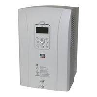
LSIS SV-iS7 series User Manual (58 pages)
Brand:
LSIS
| Category:
Control Unit
| Size: 2 MB
Table of Contents
English
5
Safety Precaution
3
Table of Contents
5
Installation Conditions
7
Product Standard
8
Installation
10
Ready for Synchronization Operation
13
Position Sync Operating
15
Speed Sync Operating
28
조선말/한국어
34
1 기본 사항
35
사용 환경
35
제품 규격
35
2 설치 및 운전 준비
37
설치
37
동기 운전 준비
40
3 운전
42
위치 동기 운전
42
속도 동기 운전
52
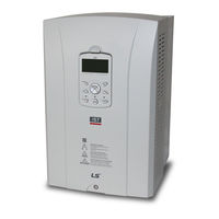
LSIS SV-iS7 series User Manual (59 pages)
CC-Link option board
Brand:
LSIS
| Category:
DC Drives
| Size: 4 MB
LSIS SV-iS7 series User Manual (22 pages)
Pulse Encoder Interface
Brand:
LSIS
| Category:
Recording Equipment
| Size: 2 MB
Table of Contents
Table of Contents
3
Chapter 1. Introduction
4
What this Product Contains
4
Option Module
4
Installment
5
Chapter 2. Terminal Block Specification
6
Name and Description
6
Power Specification for Terminal Block
6
The Wiring Example of Pulse Encoder Option Module
7
Chapter 3. Encoder Wiring and Switch Setting
9
12/15V Complementary or Open Collector
9
Line Drive
9
Chapter 4. Precaution When Encoder Wiring
11
Check the Axis Connection between the Motor and Encoder in Installment
11
The Method of Wiring of Encoder Signal Cable
11
1 소개
15
제품 구성품
15
옵션 외관
15
설치
16
2 단자대 규격
17
단자대 명칭 및 설명
17
단자대 전원규격
17
Pulse Encoder 옵션보드 결선 예
18
Pull Up/Down 저항 연결 사용시
18
Plc 연결 사용시
18
12/15V Complementary 또는 오픈 콜렉터
19
라인 드라이브
19
4 Pulse Encoder Module 과 Encoder 결선 시 주의 사항
20
Encoder 취부 시 전동기 축과 Encoder 축간의 결합 상태 확인
20
Encoder 신호선의 결선 방법
20
LSIS SV-iS7 series Manual (39 pages)
Brand:
LSIS
| Category:
Computer Hardware
| Size: 0 MB
Advertisement
Related Products
LSIS sv-ig5a
LSIS SV-iV5 Series
LSIS SV0075iS7-2/4
LSIS SV0185iS7-2
LSIS SV055iV5-2
LSIS SV075iV5-2
LSIS SV150iV5-2
LSIS SV185iV5-2
LSIS SV300iV5-2
LSIS SV185iV5-4
LSIS Categories
Controller
Inverter
Control Unit
DC Drives
Relays
More LSIS Manuals
Login
Sign In
OR
Sign in with Facebook
Sign in with Google
Upload manual
Upload from disk
Upload from URL