LSIS SV-iS7 series User Manual
Sv-is7 series 0.75-75kw[200v] 0.75-375kw[400v]
Hide thumbs
Also See for SV-iS7 series:
- User manual (255 pages) ,
- Manual (131 pages) ,
- User manual (64 pages)
Table of Contents
Advertisement
Quick Links
Advertisement
Table of Contents
Troubleshooting

Related Manuals for LSIS SV-iS7 series


Summary of Contents for LSIS SV-iS7 series
- Page 2 Be sure to understand function, performance, installation, and operation of the product by reading through this User's Manual completely prior to your use of SV-iS7 series inverter that you have purchased. In addition, you are required to have this Us- er's Manual properly delivered to the end-user and mainte- nance manager.
-
Page 3: Safety Instructions
Safety Instructions Safety Instructions To prevent injury and property damage, follow these instructions. Incorrect operation due to ignoring instructions will cause harm or damage. The seriousness of which is indicated by the following symbols. Symbol Meaning This symbol indicates the possibility of death or Warning serious injury. - Page 4 Safety Instructions WARNING Do not remove the cover except for periodic inspections or wiring, even if the input power is not applied. Otherwise, you may access the charged circuits and get an electric shock. Wiring and periodic inspections should be performed at least 10 minutes after disconnecting the input power and after checking the DC link voltage is discharged with a meter (below DC 30V).
- Page 5 Safety Instructions Caution for Use Transportation and Installation Be sure to carry inverter in a proper way suitable for its weight, or it may result in damage to inverter. Be sure to use heat-treated wooden crate when you adopt wooden packaging for the product.
- Page 6 Safety Instructions Be certain to use the inverter under the following conditions. Environment Description - 10 ~ 40 (Non-frozen) Ambient Temperature (Less than 80% load is recommended at 50 .) Ambient Humidity Below 90% RH (Dewdrop should not be formed) Storage -20 ~ 65 Temperature...
- Page 7 Safety Instructions Adjustment before starting trial operation Do not supply the excessive range of voltage displayed in the user manual to the each terminal. It may cause damage to the inverter. Current hunting can be occurred in the low speed territory during testing. It occurs where the capacity is above 110kW with no-load and the axis is not connected.
- Page 8 Safety Instructions Be sure to set the parameters once more, in case of initialization of parameters, all values of parameters is set to values of factory setting. High speed operation can be set easily, therefore be sure to check the performance of motor or machine before changing parameter value.
- Page 9 Safety Instructions General Instruction The drawing in this user manual is represented the details of the inner inverter, so, the drawing is described without cover part and circuit breaker. But, cover and circuit breaker should be mounted before the operation following to the instruction of user manual.
- Page 10 Introduction to the Manual This manual describes the specifications, installation, operation, functions and maintenance of SV-iS7 series inverter and is for the users who have basic experience of using an inverter. It is recommended you read carefully this manual in order to use SV-iS7 series inverter properly and safely.
- Page 11 Contents Chapter 1 Basics What You Should Know before Use - - - - - - - - - - - - - - - 1.1.1 Check of product - - - - - - - - - - - - - - - 1.1.2 Parts - - - - - - - - - - - - - - -...
- Page 12 Contents 2.1.6 Other commons - - - - - - - - - - - - - - - Chapter 3 Installation Installation - - - - - - - - - - - - - - - 3.1.1 Cautions before installation - - - - - - - - - - - - - - - 3.1.2 Exterior and Dimension...
-
Page 13: Table Of Contents
Contents Control terminal line diagram 4.1.9 - - - - - - - - - - - - - - - 4-17 (Basic I/O terminal block below 22kW) 4.1.10 Control terminal line diagram - - - - - - - - - - - - - - - 4-21 (Insulated I/O terminal block above 30kW) 4.1.11... - Page 14 Contents 6.1.4 Sequential frequency setting - - - - - - - - - - - - - - 6-11 6.1.5 Operating command setting method - - - - - - - - - - - - - - 6-12 6.1.6 Prevention of forward or reverse rotation: - - - - - - - - - - - - -...
- Page 15 Contents 8.1.6 Parameter mode – Output terminal block - - - - - - - - - - - - - - - 8-20 function group ( OUT) 8.1.7 Parameter mode – Communication function - - - - - - - - - - - - - - - 8-25 group ( COM) 8.1.8...
- Page 16 Contents 10.1 Functional Safety - - - - - - - - - - - - - - - 10-1 10.1.1 Safety Standard product - - - - - - - - - - - - - - - 10-1 10.1.2 Safety function description and wiring - - - - - - - - - - - - - - -...
-
Page 17: What You Should Know Before Use
Chapter 1 Basics 1.1 What You Should Know before Use 1.1.1 Check of product Take the inverter out of the box, check the rating shown on a side of the product body and whether the inverter type and rated output are exactly what you ordered. Check also whether the product has been damaged during delivery. -
Page 18: Parts
Chapter 1 Basics 1.1.2 Parts If you have any doubt about the product or found the product damaged, call our company’s branch offices (see the back cover of the manual). 1.1.3 Preparation of device and Parts for operation Preparation for operation might slightly vary. Prepare parts according to the use. 1.1.4 Installation Make sure you install the product correctly considering the place, direction or surroundings in order to prevent decrease in the life and performance of the... -
Page 19: Names And Uses Of Parts
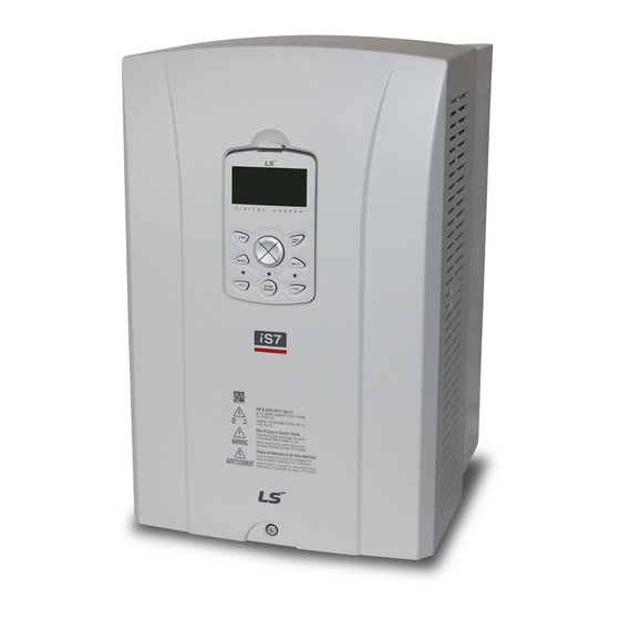
Chapter 1 Basics 1.2 Names and Uses of Parts 1.2.1 End product (less than 75 kW) Keypad Front cover: Remove it when wiring Screw to fix the front Wiring bracket Ground terminal Cooling FAN 1.2.2 When the front cover is removed (less than 75 kW) Communication option Keypad... -
Page 20: When The Front Cover Is Removed (More Than
Chapter 1 Basics 1.2.3 End Product (more than 90kW) Keypad Cooling fan Screw to fix upper front Upper front cover cover (left side) Screw to fix Screw to fix lower upper front front cover (left side) Screw to fix the lower front cover Lower front cover (right side) -
Page 21: Rated Input And Output
Chapter 2 Specifications 2.1 Specifications 2.1.1 Rated Input and Output : Input voltage of 200V class (0.75~22kW) Type : SV xxx iS7 – 2x 0008 0015 0022 0037 0055 0075 0110 0150 0185 0220 [HP] Motor Applied [kW] 0.75 18.5 Rated Capacity 12.2 17.5 22.9 28.2 33.5 [kVA]... - Page 22 Chapter 2 Specifications 2.1.3 Rated Input and Output : Input voltage of 400V class (0.75~22kW) Type : SV xxx iS7 – 4x 0008 0015 0022 0037 0055 0075 0110 0150 0185 0220 [HP] Motor Applied [kW] 0.75 18.5 Rated Capacity 12.2 18.3 22.9 29.7 34.3 [kVA] Rated...
-
Page 23: Other Commons
Chapter 2 Specifications 2.1.5 Rated Input and Output : Input voltage of 400V class (185~375kW) Type : SV xxx iS7 – 4x 1850 2200 2800 3150 3750 [HP] Motor Applied [kW] Rated Capacity [kVA] 286 Rated Current[A] 0 ~ 400 [Hz] Output Frequency (Sensorless-1:0~300Hz, Sensorless-2,Vector:0~120Hz) Output Voltage [V]... - Page 24 Chapter 2 Specifications 2) Operation Selectable among keypad/ terminal block/ Operating Method communication operation Analog : 0 ~ 10[V], -10 ~ 10[V], 0 ~ 20[mA] Frequency Setting Digital : keypad PID control, up-down operation, 3-wire operation, DC break, Frequency limit, Frequency jump, Second function, Slip compensation, Reverse rotation prevention, Auto restarting, Operating Function Inverter By-pass, Auto tunning Flying Start, Energy buffering,...
- Page 25 Chapter 2 Specifications 3) Protective Function Over voltage, Low voltage, Over current, Earth current detection, Inverter overheat, Motor overheating, Output imaging, Overload Trip protection, Communication error, Frequency command loss, Hardware failure, Cooling fan failure, Pre-PID failure, No motor trip, External break trip, etc. Stall prevention, Overload, Light load, Encoder error, Fan failure, Alarm Keypad command loss, Speed command loss.
- Page 26 Chapter 2 Specifications...
- Page 27 Chapter 3 Installation 3.1 Installation Be sure to check mechanical and electrical installation environment before you start the inverter. Read through the checking list below. Be sure to read through the Caution for Safety on this User's Manual prior to the operation of inverter. Checking List Mechanical Installation Checking List Be sure to check the surrounding environment is allowed for operation.
-
Page 28: Cautions Before Installation
Chapter 3 Installation 3.1.1 Cautions before installation Be careful so that the plastic parts of the inverter may not be damaged. Do not move the product holding the cover only. Do not install the product where there i s vibration, a press or truck. Life of the inverter greatly influenced by the surround ing temperatures, make sure that the surrounding temperature does not exceed th e permitted temperature (-10 ~ 50 C). - Page 29 Chapter 3 Installation Remark Over 50cm, B : over 20cm is necessary when you install an inverter above 30kW. Caution Avoid direct rays of light or a warm and humid place. Install the inverter in a closed panel or clean place free from foreign substances such as oil mist and fiber dust.
-
Page 30: Exterior And Dimension
Chapter 3 Installation 3.1.2 Exterior and Dimension (UL Enclosed Type 1, IP21 Type) 1) SV0008-0037iS7 (200V/400V) mm ( inches ) Inverter capacity SV0008~0037 150(5.90) 127(5.00) 284(11.18) 257(10.11) 18(0.70) 200(7.87) 5(0.19) 5(0.19) iS7 - 2/4... - Page 31 Chapter 3 Installation 2) SV0055-0075iS7 (200V/400V) mm ( inches ) Inverter capacity SV0055~0075 200(7.87) 176(6.92) 355(13.97) 327(12.87) 19(0.74) 225(8.85) 5(0.19) 5(0.19) iS7 - 2/4...
- Page 32 Chapter 3 Installation 3) SV0110-0150iS7 (200V/400V) mm ( inches ) Inverter capacity SV0110~0150 250(9.84) 214.6(8.44) 385(15.15) 355(13.97) 23.6(0.92 284(11.18) 6.5(0.25) 6.5(0.25) iS7- 2/4...
- Page 33 Chapter 3 Installation 4) SV0185-0220iS7 (200V/400V) mm ( inches ) Inverter capacity SV0185~0220 280(11.02) 243.5(9.58) 461.6(18.17) 445(17.51) 10.1(0.39) 298(11.73) 6.5(0.25) 6.5(0.25) iS7- 2/4...
- Page 34 Chapter 3 Installation 5) SV0300-iS7 (200V, IP00 Type) mm ( inches ) Inverter W2/W3 capacity SV0300 265.2 iS7-2 (11.81) (7.48) (22.44) (21.73) (0.39) (10.44) (0.39) (0.39)
- Page 35 Chapter 3 Installation 6) SV0370-0450iS7 (200V, IP00 Type) mm ( inches ) Inverter W2/W3 capacity SV0370~04 281.2 (14.5 (10.63) (24.8) (23.97) (0.43) (11.07) (0.39) (0.39) iS7-2...
- Page 36 Chapter 3 Installation 7) SV0300-0450iS7 (400V) mm ( inches ) Inverter capacit SV300~ DCR Type iS7-4 300.1 242.8 594.1 24.1 303.2 (11.81) (9.55) (23.38) (22.12) (0.94) (11.93) (6.33) (0.39) (0.39) Non-DCR Type 271.2 (10.67( (5.78) 3-10...
- Page 37 Chapter 3 Installation 8) SV0550-0750iS7 (200V, IP00 Type) mm ( inches ) Inverter W2/W3 capacity SV0550~0 723.5 15.5 355.6 (18.3) (15.0) (29.52) (28.48) (0.61) (14.0) (0.43) (0.43) iS7-2 3-11...
- Page 38 Chapter 3 Installation 9) SV0550-0750iS7 (400V) mm ( inches ) Inverter capacity DCR Type 373.3 211.5 SV0055~ (14.69) (8.32) 370.1 312.8 663.5 631.4 24.1 0075 Non-DCR (14.57) (12.31) (26.12) (24.85) (0.94) (0.39) (0.39) iS7-4 Type 312.4 150.6 (12.29) (5.92) 3-12...
- Page 39 Chapter 3 Installation 10) SV0900-1100iS7 (400V, IP00 Type) mm ( inches ) Inverter capacity SV0900~ 783.5 15.5 422.6 1100 (20.07) (15.0) (13.77) (30.84) (29.88) (0.61) (16.63) (0.43) (0.43) iS7-4 3-13...
- Page 40 Chapter 3 Installation 11) SV1320-1600iS7 (400V, IP00 Type) mm ( inches ) Inverter capacit SV1320 15.5 422.6 ~1600 (20.07) (15.0) (13.77) (33.89) (32.93) (0.61) (16.63) (0.43) (0.43) iS7-4 3-14...
- Page 41 Chapter 3 Installation 12) SV1850-2200iS7 (400V, IP00 TYPE) mm ( inches ) Inverter capacity 3-15...
- Page 42 Chapter 3 Installation 13) SV2800iS7 (400V, IP00 TYPE ) Inverter capacity 3-16...
- Page 43 Chapter 3 Installation 14) SV3150-3750iS7 (400V, IP00 TYPE ) mm ( inches ) Inverter capacity SV3150/ 1302.5 1271.5 3750iS7-4 (36.30) (22.83) (22.83) (51.28) (50.06) (0.59) (19.49) (0.55) (0.55) 3-17...
-
Page 44: External Dimension
Chapter 3 Installation 3.1.3 External dimension (UL Enclosed Type12, IP54 Type) 1) SV0008-0037iS7 (200V/400V) mm ( inches ) Inverter capacity 204.2 95.1 SV0008~0037 (8.03) (5.0) (16.49) (10.11) (3.74) (8.18) (0.19) (0.19) iS7-2/49 3-18... - Page 45 Chapter 3 Installation 2) SV0055-0075iS7 (200V/400V) mm ( inches ) Inverter capacity 460.6 88.1 232.3 SV0055~0075 (10.0) (6.92) (18.13) (12.87) (3.46) (9.14) (0.19) (0.19) iS7- 2/4 3-19...
- Page 46 Chapter 3 Installation 3) SV0110-0150iS7 (200V/400V) mm ( inches ) Inverter capacity 313.1 214.6 590.8 101.7 294.4 SV0110~0150 (12.32) (8.44) (23.25) (13.97) (4.0) (11.59) (0.25) (0.25) iS7-2/4 3-20...
- Page 47 Chapter 3 Installation 4) SV0185-0220iS7 (200V/400V) mm ( inches ) Inverter capacity 343.2 243.5 750.8 91.6 315.5 SV0185~0220 (13.51) (9.58) (29.55) (17.51) (3.60) (12.42) (0.25) (0.25) iS7-2/4 3-21...
-
Page 48: Dimension And Weight Of Frame
Chapter 3 Installation 3.1.4 Dimension and Weight of frame (UL Enclosed Type 1, IP 21Type) Non EMC EMC&DCL Only EMC Only DCL Inverter and DCL Weight Product Product Capacity [mm] [mm] [mm] Product [Kg] weight[Kg] weight[Kg] weight[Kg] SV0008iS7-2/4 150 SV0015iS7-2/4 150 SV0022iS7-2/4 150 SV0037iS7-2/4 150 SV0055iS7-2/4 200... - Page 49 Chapter 3 Installation Non EMC EMC&DCL Only EMC Only DCL Inverter and DCL Weight Product Product Capacity [mm] [mm] [mm] Product [Kg] weight[Kg] weight[Kg] weight[Kg] SV1100iS7-4 783.5 422.6 SV1320iS7-4 422.6 SV1600iS7-4 422.6 SV1850iS7-4 1078 -200 SV2200iS7-4 1078 -200 SV2800iS7-4 1138 252- SV3150iS7-4 1302.5...
- Page 50 Chapter 3 Installation 3.1.5 Dimension and Weight of Frame (UL Enclosed Type 12, IP54 Type) Inverter EMC&DCL Only EMC Only DCL EMC&DCL Capacity [mm] [mm] [mm] Weight[Kg] Weight[Kg] Weight[Kg] Weight[Kg] SV0008iS7-2/4 204.2 SV0015iS7-2/4 204.2 SV0022iS7-2/4 204.2 SV0037iS7-2/4 204.2 SV0055iS7-2/4 254 460.6 232.3 12.8 10.2...
-
Page 51: Installation Guide
Chapter 3 Installation 3.1.6 Installation Guide (UL Enclosed Type12, IP54 Type) 1) How to separate IP54 keypad cover and keypad - Release the upper/lower screw on the transparent keypad cover and then separate the transparent cover from the inverter. - Separate the keypad from the inverter. 2) How to separate IP54 front cover - Loosen the captive screws (nine or thirteen, depending on the size of the frame) around the edge of the cover. - Page 52 Chapter 3 Installation 3) Mounting the inverter - Remove the four rubber packings on the corner. - Mount the inverter onto fixing hole on the panel and securely tighten the four screws or bolts. - Place the four rubber packings to the each corner. 4) Power cable wiring - Connects the input/output power cable as followed picture.
- Page 53 Chapter 3 Installation 5 How to attach the IP54 front cover - Place the front cover matching with plate hole. - Securely tighten the screw at the corner of front cover. - Connect the cable to the keypad and then place the front cover on the inverter. - Place the transparent keypad cover on the keypad and tighten the upper/lower screw.
- Page 54 Chapter 3 Installation 3-28...
-
Page 55: Chapter 4 Wiring
Chapter 4 Wiring 4.1 Wiring Do the wiring of inverter and then check the wiring of main circuit and control circuit before starting it. Read through the checking list as below. Checking List Inverter, Peripherals, Option card Is the inverter supplied in the form as ordered? Are the type and numbers of peripherals (Resistance, DC reactor, Noise filter, etc.) supplied as ordered? Is the type of option supplied as supplied? - Page 56 Chapter 4 Wiring Checking List Control Circuit Wiring Is a twisted pair shielded wire adopted for the inverter control circuit wiring Is the covered wire with shield connected with the ground terminal In the event it is operated in 3-Wire sequence, is the control circuit wiring done after the parameter of multi-function contact input terminal is modified Is the wiring of the optional devices done properly...
-
Page 57: How To Separate Front Cover When Wiring
Chapter 4 Wiring 4.1.1 How to separate front cover when wiring Remove Keypad on the product and release fixed volt of the lower end of up cover. 1) How to separate Keypad Under pressing the lower end of keypad, pull the upper part of keypad. - Page 58 Chapter 4 Wiring 3) How to separate front cover [IP21 Type] I/O board control Separate circuit Terminal front cover releasing the fixed bolt. Power circuit terminal [IP54 Type] Separate the transparent keypad cover releasing fixed bolt and then separate keypad. Separate the front cover releasing fixed bolt.
- Page 59 Chapter 4 Wiring 4.1.2 How to separate front cover when wiring (90~375 kW 400V, 30-75kW 200V) Releasing the right/left fixed bolt on the lower front cover and get down the lower front cover and then open it. Now, you can wire power part (R/S/T, P/N, U/V/W) and signal cable (terminal block, encoder option, communication option, PLC option etc.).
-
Page 60: Built-In Emc Filter
Chapter 4 Wiring 4.1.3 Built-in EMC Filter The product which has a built-in EMC filter is efficient for reducing conductive and radiated noise from the input part of inverter. Turns On the On/Off switch of EMC filter to perform the EMI function if you are select the product which has a built-in EMC filter. (However, when unable to use EMC filter or due to the asymmetric structure of the ground to use, EMC filter of on/off swich is set to off 1) How to set EMC Filter functions (Less than 7.5kW Products) - Page 61 Chapter 4 Wiring 3) How to set EMC Filter functions (11~22kW Products) EMC filter ON/OFF set terminal is located in lower part of the 11~22KW Terminal as shown figure below. Initial set isON. When the green wire is connected in upper metal connection terminal, EMC filter is ON and EMC filter is OFF if it is connected in insulated connection terminal.
-
Page 62: Wiring Precaution
Chapter 4 Wiring 4.1.4 Wiring precaution 1) The internal circuits of the inverter will be damaged if the incoming power is connected and applied to output terminals (U, V, W). 2) Use ring terminals with insulated caps when wiring the input power and motor wiring. 3) Do not leave wire fragments inside the inverter. -
Page 63: Terminal Wiring Diagram
Chapter 4 Wiring Grounding wire size ( mm²) Inverter Capacity 200V class 400V class 0.75 ~ 3.7kW 5.5 ~ 7.5 kW 11 ~ 15 kW 18.5 ~ 22 kW 30 ~ 45 kW 55 ~ 75 kW 90 ~ 110 kW 132 ~ 220 kW 280 ~ 315 kW 375 kW... - Page 64 Chapter 4 Wiring 4) Wiring of 90~160kW Product R(L1) S(L2) T(L3) P2(+) N(-) 5) Wiring of 185~220kW Product R(L1) S(L2) T(L3) P2(+) N(-) 6) Wiring of 280~375kW Product R(L1) S(L2) T(L3) P1(+) P2(+) N(-) Note Products over 11kW have a linear arrangement of terminal blocks. Products for 0.75~22kW have built-in DC Reactor, so it does’t necessary any other DC Reactor connection.
- Page 65 Chapter 4 Wiring 4.1.7 Terminals of main circuit 1) 0.75 ~ 22 kW (200V/400V) (1) Built-in dynamic braking unit used Connect P(+) and B terminal of inverter to the dynamic braking unit when built-in dynamic unit is used. R(L1) S(L2) T(L3) P(+) N(-)
- Page 66 Chapter 4 Wiring 2) 30 ~ 75 kW (200V, 400V) R(L1) S(L2) T(L3) P1(+) N(-) P N B1 B2 3 Phase AC Input Motor Terminal Symbol Terminal Name Description R(L1), S(L2), T(L3) AC power supply input Connects normal AC input (+)DC link voltage terminal, P1(+) (+)DC voltage terminal...
- Page 67 Chapter 4 Wiring 3) 90 ~ 160 kW (400V) R(L1) S(L2) T(L3) P2(+) N(-) 3 Phase P N B1 B2 AC Input Dynamic Motor brake unit Dynamic brake resistor Terminal Symbol Terminal Name Description R(L1), S(L2), T(L3) AC power supply input Connects normal AC input P(+) (+)DC voltage ternimal (+)DC link voltage terminal N(-)
-
Page 68: Specifications Of Power Terminal Block And
Chapter 4 Wiring 4.1.8 Specifications of power terminal block and Exterior fuse Cable Terminal Exterior fuse Screw torque mm² Inverter applied Screw (Kgf·cm) size R,S,T U,V,W R,S,T U,V,W Current Voltage 0.75 kW 7.1~12 1.5 kW 7.1~12 2.2 kW 7.1~12 3.7 kW 7.1~12 5.5 kW 7.1~12... - Page 69 Chapter 4 Wiring Cable Terminal Exterior fuse Screw torque mm² Inverter applied Screw (Kgf·cm) size R,S,T U,V,W R,S,T U,V,W Current Voltage 220 kW 182.4~215.0 800A 280 kW 182.4~215.0 1000A 2x40 315 kW 182.4~215.0 2x200 2x200 2x400 1200A 2x50 375 kW 182.4~215.0 2x250 2x250 2x500...
- Page 70 Chapter 4 Wiring 4.1.9 Control terminal line diagram (Basic I/O terminal block, below 22kW) NPN (Sink) /PNP (Source) set terminal I / PTC set terminal 1) How to set NPN (Sink)/PNP (Source) iS7 serves 2 sequence input terminals of control circuit: NPN mode (Sink mode) and PNP mode (Source mode).
- Page 71 Chapter 4 Wiring (2) PNP mode (Source mode) – When use inner source Set NPN (Sink)/PNP (Source) switch into PNP. 24 (24V inner source) is common terminal of contact point input signal. PNP mode (Source mode) – Set NPN (Sink)/PNP (Source) switch into PNP When use exterior source.
- Page 72 Chapter 4 Wiring 1) 0.75 ~ 22kW (Basic I/O) Relay2 Open power (Normal Collector supply Open) Output Relay1 (Normal Open) In case of analog In case of voltage input with analog Digital contact point potentiometer current input input (4~20 mA (-10V~+10V (NPN/PNP, input)
-
Page 73: Control Terminal Line Diagram
Chapter 4 Wiring 4.1.10 Control terminal line diagram (Insulated I/O terminal block, above 30kW) NPN (Sink)/PNP (Source) Set terminal / PTC Set terminal 1) 30~375kW (Insulated I/O) Open Relay2 Collector (Normal power Output Open) supply Relay1 (Normal Open) In case of In case of Digital contact point analog voltage... - Page 74 Chapter 4 Wiring When setting the frequency reference source with analog voltage (V) or current (I), the reflection of frequency for the analog input is based on when the analog input is actually received. Taking the voltage input for instance, the state no voltage is applied to V1 is not 0V, but 0V is input to V1 in fact is 0V In case of analog voltage input, accurate linear property is shown by Bipolar at the state - 10 ~ 0 ~ 10V input is received while by Unipolar at the state 0 ~ 10V input if received.
-
Page 75: Control Circuit Terminal
RS-485 signal line (Refer to ‘Communication Function’ contained in iS7 User RS-485 signal S+,S-, CM Manual. You can download it from LSIS website. input terminal (http://www.lsis.biz). This provided manual is the simple version of iS7 User Manual. 4-21... - Page 76 Chapter 4 Wiring 4.1.12 Specifications of signal terminal block distribution Terminal Cable size Electric specifications Type Name P1~P8 Multi-function input terminal Contact point common terminal Common earth for multi function input (In case of Basic I/O, terminal CM is different from 5G) Analog frequency setting Output voltage : +12V 0.33...
-
Page 77: Operation Checking
Chapter 4 Wiring 4.2 Operation Checking IS7 provides EASY START MODE helping with the basic parameter setting using the keypad by distribution shown above when power is first supplied. 4.2.1 Easy start Easy Start gets started when power is first supplied after you purchase the product or power is re-supplied after the set parameters are all initialized. -
Page 78: Checking For Normal Working
Chapter 4 Wiring 4.2.3 Checking for normal working 1) Motor forward/reverse direction and Normal working checking by KEYPAD operation After setting Cmd Source of DRV-06 is 0 : Keypad, Freq Ref Src of DRV-07 is 0 : Keypad-1 and set DRV-01 : Cmd Frequency into temporary speed, Command forward operation by pressing FWD please. -
Page 79: How To Use Keypad
Chapter 5 How to Use Keypad 5.1 How to Use Keypad 5.1.1 Standard KEYPAD appearance and description (Graphic keypad) Standard Keypad is used in Inverter parameter setting, Monitor display and Inverter operations. 1) Dimensions... - Page 80 Chapter 5 How to Use Keypad 2) Key Functions 14. Move to UP 1. Cancel(ESC) 13. PROGRAM set 2. Move to Left 12. Move to Right 3. MODE selection 11. Multi-Function 10. Move to down 4.Reverse operation 9. Forward operation LED 5.
- Page 81 Chapter 5 How to Use Keypad 3) Composition of Display (1) Monitor Mode Multi-function Key Inverter Operating Status Operating/Frequency Status Display Item Mode Display Monitor Mode MON T/K N STP 0.00Hz Display Item 1 Monitor Mode Monitor Display Item 2 Monitor Mode Display Item 3 (2) Parameter change display...
- Page 82 Chapter 5 How to Use Keypad (4) Monitor Display Items Function Display Description Monitor Mode Parameter Mode Mode U and M USR & Macro Mode Display Trip Mode Config Mode Keypad operation command FBus Option operation command Operating Application Option operation command Command Built-in 485 operation command Terminal block operation command...
- Page 83 Chapter 5 How to Use Keypad Function Display Description Operating Operating forward Status Operating reversely DC output Warning Stalling Speed Search SW OC controlled HW OC controlled Auto Tuning (5) Status Display Items: see “Operating status monitoring” on this chapter 5.1.7. (6) Monitor Mode Display Items: see “Operating status monitoring”...
-
Page 84: Menu Composition
Chapter 5 How to Use Keypad 5.1.2 Menu composition SV-iS7 series inverter consists of the following 5 modes. Each mode has its own function items suitable for the properties and especially the parameter mode displays the functions necessary for inverter operation in groups. - Page 85 Chapter 5 How to Use Keypad Mode Display Description In case of a failure during operation, the failure type and information on the operating frequency/current/ voltage at the time of the failure Trip mode occurring are displayed. You can also monitor the type of the trips that previously occurred.
- Page 86 Chapter 5 How to Use Keypad Mode Display Description Application Sets functions related to the encoder option and option group PLC option card, if they are used. Protection Can set functions for protecting the motor and group inverter. Motor 2 This group is displayed if you select Motor #2 function among the multi-function input terminal functions...
-
Page 87: Mode Shift
Chapter 5 How to Use Keypad 5.1.3 Mode shift MON T/K N STP 0.00Hz - Power on, a display emerges as shown on the left. The present mode is the monitor mode. - Press Mode key once. DRV N STP 0.00Hz Jump Code - You have shifted to Parameter Mode. -
Page 88: Group Shift
Chapter 5 How to Use Keypad 5.1.4 Group shift 1) Group Shift in Parameter Mode If you press Right key in the Parameter Mode, the display changes as follows. If you press Left key, the display order will be reversed. MON T/K N STP 0.00Hz - Power on, a display emerges as shown on... -
Page 89: Code (Function Item) Shift
Chapter 5 How to Use Keypad 5.1.5 Code (Function Item) shift 1) Code shift (function Items) in modes and groups Using Up and Down keys: The following figures give an example of shifting the code by using Up and Down keys in DRV and BAS of Parameter Mode. Code shift in other modes are the same. -
Page 90: Parameter Setting
Chapter 5 How to Use Keypad 5.1.6 Parameter setting 1) Parameter setting in modes and groups This gives an example of changing frequency in the Drive Group of Parameter Mode. You can do so too in other modes or groups. STP 0.00Hz Jump Code - This is the initial display of Parameter Mode. - Page 91 Chapter 5 How to Use Keypad 5.1.7 Operating status monitoring 1) Using monitor mode You can monitor 3 items at a time in Monitor Mode. Some items including frequency can be edited. Displayed items can be selected by the user in Config Mode(CNF).
- Page 92 Chapter 5 How to Use Keypad 2) Possible to monitoring items Mode Code Function Display Setting Range Initial Value Anytime Para Frequency 0 : Frequency Monitor Line-1 Speed 0 : Frequency Output Current 2 :Output Current Monitor Line-2 3 :Output Voltage Output Voltage Monitor Line-3 Output Power...
-
Page 93: Failure Status Monitoring
Chapter 5 How to Use Keypad 5.1.8 Failure status monitoring 1) Failure during operation TRP current - In case of a failure during operation, the Over Voltage (01) 01 Output Freq mode automatically shifts to Trip Mode and 48.30 Hz the type of the current failure is displayed. - Page 94 Chapter 5 How to Use Keypad 3) Saving and monitoring of failure history Previous failures are saved in Trip Mode. Up to 5 failures can be saved. Failure history is saved not only by Reset but also in case of a low voltage failure due to power off.
-
Page 95: How To Initialize Parameter
Chapter 5 How to Use Keypad 5.1.9 How to initialize parameter You can initialize the parameter that has been changed by the user to the initial state at the time of delivery. Not only the entire parameter but a group of the parameter mode can be selected and initialized. - Page 96 Chapter 5 How to Use Keypad 5-18...
-
Page 97: Basic Functions
Chapter 6 Basic Functions 6.1 Basic Functions 6.1.1 How to set frequency (When you want to set frequency) Group Code No. Function Display Initial Display KeyPad-1 KeyPad-2 Freq Ref Src Int 485 Encoder Fied Bus Select the frequency setting method in code 07 of DRV Group. Digital setting by using the keypad, analog setting by using voltage (V1) and current (I1) input of the control terminal block and built-in RS485 port or communication option are available for operating frequency setting from the external controller. - Page 98 Chapter 6 Basic Functions 3) Frequency setting by voltage input (V1 terminal) of the terminal block: V1 Group Code No. Function Display Setting Displayed Unit Freq Ref Src Enter -10~+10V or 0~+10V using the voltage (V1) input terminal of the terminal block. If you enter -10~+10V, you can change the revolution direction of the motor according to the symbol of the voltage signals.
- Page 99 Chapter 6 Basic Functions IN-05 V1 Monitor : displays the voltage input into the V1 terminal. This is used for monitoring the currently input voltage. IN-07 V1 Filter : used when the set frequency value fluctuates greatly due to the environment such as noise.
- Page 100 Chapter 6 Basic Functions Output Frequency 60 .00 59 .94 0 . 12 0 . 06 Analog Input 0 . 025 0.1 9.925 0.075 0. 175 9. 975 (3) If -10~+10V is input, Group Code No. Function Display Setting Displayed Setting Range Unit Freq Ref Src...
- Page 101 Chapter 6 Basic Functions The output frequency of bipolar voltage input (-10~+10V) is as follows. Forward Output Frequency - 10 ~ 0 [V ] 0 ~ 10 [ V ] Input Voltage Reverse Output Frequency IN-12 V1 –volt x1’~ IN-15 V1 –Perc y2’: You can set the slope and offset value of the output frequency of (-) input voltage as follows.
- Page 102 Chapter 6 Basic Functions 4) Frequency setting by current input into terminal block (I1 Terminal) Group Code No. Function Display Setting Displayed Setting Range Unit Freq Ref Src Freq at 100% 60.00 0.00~ Max Freq I1 Monitor 0.00 0~20 I1 Filter 0~10000 msec I1 Curr x1...
- Page 103 Chapter 6 Basic Functions 5) Frequency command by advanced I/O option card You can input the frequency command by using -10~+10V (V2 terminal) and 0~20mA (I2terminal) if you mount an extended I/O card on the inverter option slot. -10~+10V Input Group Code No.
- Page 104 Chapter 6 Basic Functions 6) Frequency setting by Encoder Option Card (If you want use pulse input to frequency command) Group Code No. Function Display Setting Displayed Setting Frequency Unit Freq Ref Src Encoder 0.00~Max. Freq. Freq at 100% 60.00 Enc Opt Mode Reference Enc Type Sel...
- Page 105 Chapter 6 Basic Functions 7) Frequency setting by RS-485 Communication : Int 485 Group Code No. Function Display Setting Displayed Setting Frequency Unit Freq Ref Src Int 485 Int485 St ID 0~250 0 ModBus RTU Int485 Proto 1 ModBus ASCII LS Inv 485 Int485 BaudR 9600...
-
Page 106: Analog Command Frequency Fixation
Chapter 6 Basic Functions 6.1.2 Analog command frequency fixation Group Code No. Function Display Setting Displayed Setting Range Unit Keypad-1 Keypad-2 Freq Ref Src Int 485 Encoder Fied Bus 65~75 *Px Define Analog Hold 65~75 *Px : P1~P8, P9~P11 (option) This is the function of fixing the operating frequency when the terminal selected as the Analog Hold among the multi-function terminals if you set the frequency by using the analog input of the control terminal block. - Page 107 Chapter 6 Basic Functions 6.1.3 Changing frequency to revolution If you set the Hz/Rpm Sel value at “1: Rpm Display, the frequency will change into revolution. Group Code No. Function Display Setting Displayed Setting Range Unit Hz/Rpm Sel Rpm Display 6.1.4 Sequential frequency setting Group Code No.
- Page 108 Chapter 6 Basic Functions [Example of speed-8] If multi-function terminals P5, P6, P7 and P8 are set at Speed-L, Speed-M, Speed-H and Speed-X respectively, you can operate it as follows. Speed FX or RX IN-89 In Check Time: If you use the multi-function terminal for sequential frequency setting, you can set the in check time for the terminal block input within the inverter.
- Page 109 Chapter 6 Basic Functions 1) Keypad Operating Command: KeyPad Group Code No. Function Display Initial Display Unit Cmd Source KeyPad If you set the DRV Group 06 with the keypad, operation starts using the FWD and REV keys on the inverter keypad and stops using Stop key. 2) Terminal Block operating command 1 : Fx/Rx-1 Group Code No.
- Page 110 Chapter 6 Basic Functions IN-88 Run On Delay: Operation starts after the set time, too when the FX or RX terminal is input. It can be used where operation start synchronization with an outside sequence is necessary. Frequency 4) Operating Command by RS-485 Communication: Int 485 Group Code No.
- Page 111 Chapter 6 Basic Functions pattern without Speed Search. If this function is not selected, operation resumes after the operating commands is turned OFF and ON again. Power Frequency Operating command When ADV - 10 = 0 When ADV -10= 1 Caution Be careful with this function, which causes the motor to rotate as soon as the power is supplied.
- Page 112 Chapter 6 Basic Functions Caution 90 ~ 160 kW product’s acceleration initial value is 60.0sec and deceleration initial value is 90.0sec. Please do not confuse that displayed value at left bottom of keypad is D : 20.0, D : 30.0 it is applied for below 75kW product. BAS-09 Time scale : Used when precise Acc/Dec time is required due to the load characteristics or it is necessary to increase the maximum set time.
- Page 113 Chapter 6 Basic Functions 3) Setting of Acc/Dec Time by using Multi-Function Terminal Based on Operating Frequency Code Setting Group Function Display Setting Display Unit Range Below 0~600 20.0 75kW Acc Time Above 60.0 90kW Below 0~600 30.0 75kW Dec Time Above 90.0 90kW...
- Page 114 Chapter 6 Basic Functions IN-89 In Check Time : when using multi-function input terminal as setting multi-acc/dec, you can set up the time for checking terminal input inside the inverter. For example, if you set terminal input check time for 100msec and multi-function P6 is entered, you can check if other terminal input is entered for 100msec.
- Page 115 Chapter 6 Basic Functions 6.1.9 Motor output voltage adjustment (Adjusting motor voltage when input power specification differs from motor voltage specification) Group Code No. Function Display Setting Display Setting Range Unit Rated Volt 180~480 Inputs the voltage of the motor plate. The set voltage value is the output voltage value of the base frequency.
- Page 116 Chapter 6 Basic Functions 6-20...
-
Page 117: Protective Functions
Chapter 7 Checking and Troubleshooting 7.1 Checking and Troubleshooting 7.1.1 Protective functions 1) Protection from output current and input voltage Type Category Details A failure occurs when you select the motor overload failure and Over Load Latch the load exceeds the set degree. Operation can resume after PRT-20 is set at values other than 0. - Page 118 Chapter 7 Checking and Troubleshooting 2) Protection by internal circuit abnormality or external signals Type Category Details Remark A failure occurs when the inverter DC fuse Fuse Open Latch responds to over current only above 30kW. A failure occurs when the temperature of the Over Heat Latch inverter cooling fan rises over the prescribed...
- Page 119 Chapter 7 Checking and Troubleshooting Type Category Details Remark A failure occurs when resistance goes beyond prescribed value after external Thermal Latch temperature sensor is connected to the terminal Trip block. Operation resumes if PRT-34 is set at values other than 0. ParaWrite Trouble during parameter writing with the Latch...
- Page 120 Failure history will be saved and the fault output signal will be outputted. If the inverter keeps the fault state after re-inputting of power, please contact to sales representative of LSIS. * The functions of the save of failure history and the output of fault signal could not be operated in case the functions have not set or the inverter got damaged seriously.
- Page 121 Chapter 7 Checking and Troubleshooting Type Description An alarm is signified if No. 3 Enc Test is selected from BAS-20 Auto Enc Conn Tuning and no signal is input during the encoder test. Signals are Check released if ENC Tune is set among the functions of OUT31~33. An alarm is signified if No.
- Page 122 Chapter 7 Checking and Troubleshooting Type Cause of Trouble Solution The braking of the motor is too search (CON-60). fast. Check the machine brake. Decelerating time is too short Set the decelerating time higher. compared with the inertia of the load (GD Use a braking resistance device.
- Page 123 Chapter 7 Checking and Troubleshooting Type Cause of Trouble Solution amount. There is a problem with the Check whether there is any cooling system. foreign substance in the vent, air The inverter has been used duct or outlet. Over Heat longer than the replacement Replace the inverter cooling fan.
- Page 124 Chapter 7 Checking and Troubleshooting 7.1.4 Replacement of cooling fan 1) Replacement steps of the product below 7.5kW Push the bracket on the bottom to the arrow direction and pull it forward. Disconnect the connector of the fan, then you can replace the fan. <below 3.7kW>...
- Page 125 Chapter 7 Checking and Troubleshooting 3) Replacement steps of product of 18.5~22 kW 200V, 30~75kW 200V/400V (Check capacity.) Release the volts upper of the product and disconnect the connector of the fan, then you can replace the fan.
- Page 126 Chapter 7 Checking and Troubleshooting LS Vector Inverter, STARVERT-iV5, is an industrial electronic product that adopts up- to-date semiconductor device. It may have a failure caused by the ambient environment such as temperature, humidity, vibration, etc. or an excessive use of the component over its duration.
- Page 127 Chapter 7 Checking and Troubleshooting CAUTION The failure of the device used in the inverter may not be predicted in advance. The failure of the device may cause the error of input power fuse or the fault trip. If you are suspicious of the failure of device, please contact our sales representative.
- Page 128 Chapter 7 Checking and Troubleshooting 1) Check if it is from overload or not. 2) Fasten the screw tightly. Do they have There must be no 3) Check if the excessive heat? unusual record. inverter's heat sink is polluted. 4) Check the ambient temperature.
- Page 129 Chapter 7 Checking and Troubleshooting (3) Regular Checking (1 year interval) Description How to Check Judgment Criterion 1) Unfasten the 1) Megger checking connection of inverter, (between the main connect R, S, T, U, V, circuit terminal and and W terminals, and 1) To be 5M or more ground terminal) then measure the gap...
- Page 130 Chapter 7 Checking and Troubleshooting Description How to Check Judgment Criterion Check if they are Remove them by stained with trash or Check by eyes. blowing a dry air. dust 1) Clean it using anti- static cloth or cleaner. If not, replace with new circuit board 2) Do not clean the circuit board using the...
- Page 131 Chapter 7 Checking and Troubleshooting Description How to Check Judgment Criterion Check the indicator Check the value under Is the indicator value value on the display of the regulation and normal? the panel surface. standard value (4) Regular Checking (2 year interval) Description How to Check Judgment Criterion...
- Page 132 Chapter 7 Checking and Troubleshooting 7-16...
- Page 133 8.1 Table of Functions 8.1.1 Parameter mode – DRV group( DRV) * The number of page is for User’s manual uploaded at LSIS website. You can download the User’s manual which is described detailed function of parameter from website. (http://www.lsis.biz)
- Page 134 Chapter 8 Table of Functions Control Mode Shift in No. Comm. No. Function Display Name Setting Range Initial Value Operati o n Torque 0h110A torque control 0 : No X X X O O Control 0h110B jog frequency 0.5 ~ max. freq.[Hz] 10.00 O O O O O Frequency...
- Page 135 Chapter 8 Table of Functions 8.1.2 Parameter mode – Basic function group ( BAS) Control Mode Shift in No. Comm. No. Function Display Name Setting Range Initial Value Operati o n O O O O O Jump Code jump code 0 ~ 99 0 None 1 V1...
- Page 136 Chapter 8 Table of Functions Control Mode Shift in No. Comm. No. Function Display Name Setting Range Initial Value Operati o n 1 Keypad-2 2 V1 3 I1 4 V2 5 I2 6 Int 485 Trq 2nd Src 2 torque 0h1206 X X X O O 7 Encoder...
- Page 137 Chapter 8 Table of Functions Control Mode Shift in No. Comm.No. Function Display Name Setting Range Initial Value Operati o n stator resistance X O O O O Lsigma leak inductance It depends on motor X O O O O stator inductance X O O O O rotor time constant...
- Page 138 Chapter 8 Table of Functions Control Mode Shift in Initial Operati o Comm.No. Function Display Name Setting Range Value 0h124C Acc Time-4 Acc/Dec Time 4 0~600[sec] 50.0 0h124D Dec Time-4 Acc/Dec Time 4 0~600[sec] 50.0 0h124E Acc Time-5 Acc/Dec Time 5 0~600[sec] 60.0 0h124F Dec Time-5...
- Page 139 Chapter 8 Table of Functions Control Mode Shift in No. Comm.No. Function Display Name Setting Range Initial Value Operati o n 0h130C Dc-Start Time starting DC braking time 0 ~ 60 [s] 0.00 O O O X X Note8) 0h130D Dc Inj Level DC supply 0 ~ 200 [%] O O O X X...
- Page 140 Chapter 8 Table of Functions Control Mode Shift in Comm.No. Function Display Name Setting Range Initial Value Operati o n 0h1318 Freq Limit frequency li m it 0:No O O O X X 0h1319 Freq Limit Lo frequency lower l i m it 0 ~ upper li m it [Hz] 0.50 O O O X X...
- Page 141 Chapter 8 Table of Functions Control Mode Shift in Comm. No. Function Display Name Setting Range Initial Value Operation Load Spd revolution display 1 ~ 6000.0 [%] 100.0 O O O X X Gain gain 0 x 1 1 x 0.1 Load Spd revolution display 2 x 0.01...
- Page 142 Chapter 8 Table of Functions Control Mode Shift in Comm. No. Function Display Name Setting Range Initial Value Operation Restriction of compensational CompFreq frequency of Note15) 0h134C 0 ~ 10.00 [Hz] 1.00 [Hz] O O O X X Limit regeneration anc avoidance for press P-gain of...
- Page 143 Chapter 8 Table of Functions 8.1.4 Parameter mode – Control function group ( CON) Control Mode Comm. Function Shift in Name Setting Range Initial Value Display Operation Jump jump code 0 ~ 99 O O O O O Code Below 22kW 0.7 ~ 15 [kHz] 30 ~ 45kW 0.7 ~ 10 [kHz] 200V...
- Page 144 Chapter 8 Table of Functions Control Mode Comm. Function Shift in Name Setting Range Initial Value Display Operation Gain1 speed control motor period capacity proportional gain1 sensorless1, 2 ASR-SL I speed control 22 0h1416 10 ~ 9999 [ms] X O X X X Gain1 period integral calculus gain 1...
- Page 145 Chapter 8 Table of Functions Control Mode Comm. Function Shift in Name Setting Range Initial Value Display Operation PG operation O X X X X 46 0h142E PG I Gain integral calculus gain PG Slip PG operation 47 0h142F 0 ~ 200 X X X X Max% maximum sleep...
- Page 146 Chapter 8 Table of Functions 1)Control Mode Shi f t i n Function Comm. No. Name Setting Range Initial Value Opera-tion Display Keypad-1 Keypad-2 Trq Bias torque bias 0:Keypa 0h143A X X O X X setting method Int 485 FiedBus Torque -120 ~ 120 0h143B...
- Page 147 Chapter 8 Table of Functions 1)Control Mode Shi f t i n Function No. Comm. No. Name Setting Range Initial Value Operati o n Display 0 Flying Start-1 Speed search O O O X X 0h1446 SS Mode mode selection 1 Flying Start-2 Bit 0000 ~ 1111 accelerating speed...
- Page 148 Chapter 8 Table of Functions Sel c ting the Current anti - 0h145A New AHR Sel 0:No X X X X hunting Current Anti-hunting 0h145B AHR P-Gai n 0~32767 1000 X X X X Function Protection The grey code refers to hidden code, emerging only in case of setting of the code. Note 20) CON-72~75 are displayed only when CON-71,77 (KEB Select) is set as “Yes”.
- Page 149 Chapter 8 Table of Functions 0h151A I1 Perc y2 Output at I1maximumcurrent 0 ~ 100 [%] 100.00 0h151F I1 Inverti n g rotati o n di r ection change 0: No 0h1520 I1 Quanti z i n g I1 quanti z ation l e vel 0.04 ~ 10 [%] 0.04 Note 22)
- Page 150 Chapter 8 Table of Functions Control Mode Shi f t i n Function Initial INo. Comm. No. Name Setting Range Operati o n Display Value 0 NONE 0h1541 P1 Define 1 : FX 1 FX 0h1542 P2 Define 2 RX 2: RX 0h1543 P3 Define...
- Page 151 Chapter 8 Table of Functions Control Mode Shi f t i n Function Initial Comm. No. Name Setting Range Operati o n Display Value 33 -Reserved- 34 Pre Exci t e 35 Speed/Torque 36 ASR Gai n 2 37 ASR P/PI 38 Ti m er In 39 Thermal In 40 Di s Aux Ref...
- Page 152 Chapter 8 Table of Functions 8.1.6 Parameter mode – Output terminal block function group ( OUT) Control Mode Shi f t i n Function Initial Comm. No. Name Setting Range Operati o n Display Value JumpCode jump code 0 ~ 99 O O O O O 0 Frequency 1 Current...
- Page 153 Chapter 8 Table of Functions Control Mode Shi f t i n Function Initial Operati o Comm. No. Name Setting Range Display Value O O O O O 0h1608 AO2 Gain anal o g output2 gain -1000 ~ 1000 [%] 100.0 O O O O O 0h1609...
- Page 154 Chapter 8 Table of Functions Control Mode Shi f t i n Comm. Initial Function Display Name Setting Range Operati o n Value 21 0h1615 AO4 Gain anal o g output 2 gain -1000 ~ 1000 [%] 100.0 22 0h1616 AO4 Bias anal o g output 2 bi a s -100 ~ 100 [%]...
- Page 155 Chapter 8 Table of Functions Control Mode Shi f t i n Function Initial No. Comm. No. Name Setting Range Operat i o n Display Value 29 Trip 30 Lost Keypad 31 DB Warn%ED 32 ENC Tune 33 ENC Dir 34 On/Off Control 35 BR Control 36 KEB Operating...
- Page 156 Chapter 8 Table of Functions 8.1.7 Parameter mode – Communication function group ( COM) Control Mode Shi f t i n Initial Comm. No. Function Display Name Setting Range Operati o n Value O O O O O Jump Code jump code 0 ~99 bui l t-in communi c ati o n O O O O O...
- Page 157 Chapter 8 Table of Functions Control Mode Shi f t i n Initial Comm. No. Function Display Name Setting Range Opera-ti o n Value 0h1732 Para Ctrl Num 0 ~ 8 O O O O O 0h1733 0005 Para Control-1 O O O O O 0h1734 0006...
- Page 158 Chapter 8 Table of Functions Control Mode Shi f t i n Initial Comm. No. Function Display Name Setting Range Opera-ti o n Value 33 Reserved 34 Pre Excite 35 Speed/Torque 36 ASR Gain 2 37 ASR P/PI 38 Timer In 39 Thermal In 40 Dis Aux Ref 41 SEQ-1...
- Page 159 Chapter 8 Table of Functions 8.1.8 Parameter mode – Applied function group ( APP) Control Mode Shi f t i n Comm. Function Initial Name Setting Range Opera-tion Display Value O O O O O 0 ~ 99 Jump Code jump code 0 None 1 Traverse O O O X X...
- Page 160 Chapter 8 Table of Functions Control Mode Shi f t i n Initial Comm. No. Function Display Name Setting Range Operati o n Value 0 V1 1 I1 2 V2 3 I2 4 Int 485 O O O X X 0h1815 PID Feedback sel e ction 5 Encoder...
- Page 161 Chapter 8 Table of Functions Control Mode Shi f t i n Initial Comm. No. Function Display Name Setting Range Operati o n Value Beyond Level 1 Bar 2 mBar 3 Pa 4 KPa 5 Hz PID control peri o d uni t 6 rpm O O O X X 0h182A...
- Page 162 Chapter 8 Table of Functions 8.1.9 Parameter mode – Auto sequence operation group ( AUT) Control Mode Shi f t i n Function Initial No. Comm. No. Name Setting Range Operati o n Display Value O O O X X Jump Code jump code 0 ~ 99 Auto-A...
- Page 163 Chapter 8 Table of Functions Control Mode Shi f t i n Function Initial No. Comm. No. Name Setting Range Operati o n Display Value Reverse O O O X X 0h1919 Seq 1/4 Dir 1/4 operati o n di r ecti o n Forward Forward Seq 1/5...
- Page 164 Chapter 8 Table of Functions Control Mode Shi f t i n Function Initial No. Comm. No. Name Setting Range Operati o n Display Value Seq 2/2 0.01 ~ maximum O O O X X 0h192F 2/2 step frequency 22.00 Freq frequency[Hz] Seq 2/2...
- Page 165 Chapter 8 Table of Functions Control Mode Shi f t i n Function Initial No. Comm. No. Name Setting Range Operati o n Display Value Seq 2/7 O O O X X 0h1944 2/7 Acc/Dec ti m e Xcel T 0.1 ~ 600.0 [s] Seq 2/7 O O O X X...
- Page 166 Chapter 8 Table of Functions 8.1.10 Parameter mode – Option card function group ( APO) Control Mode Shi f t i n Function Initial No. Comm. No. Name Setting Range Operati o n Display Value Jump Code jump code 0 ~ 99 O O O O O 0 None 0:Non...
- Page 167 Chapter 8 Table of Functions Control Mode Shi f t i n Function Initial No. Comm. No. Name Setting Range Operati o n Display Value 1 Aux 2 Main 0h1A24 Auto Ch Time auto change ti m e 0 ~ 99:00[min] 72:00 O O O X X 0 No...
- Page 168 Chapter 8 Table of Functions 8.1.11 Parameter mode – Protective function group ( PRT) Control Mode Shi f t i n Function Initial Operat No. Comm. No. Name Setting Range Display Value -i o n Jump Code j u mp code 0 ~ 99 O O O 0 Normal Duty...
- Page 169 Chapter 8 Table of Functions Control Mode Function Initial Shift in Comm. No. Name Setting Range Display Value Operation 0h1B16 OL Tri p Ti m e overload failure time 0 ~ 60 [s] 60.0 O O O O O 0 No 0h1B19 UL Warn Sel light load alarm selection 0 : No...
- Page 170 Chapter 8 Table of Functions Control Mode Function Initial Shift in Comm. No. Name Setting Range Display Value Operation 0h1B34 Stal l Level 1 stall level 1 30 ~ 250 [%] O O X O X stall frequency 1 0h1B35 Stal l Freq 2 stall frequency 2 60.00...
- Page 171 Chapter 8 Table of Functions 8.1.12 Parameter mode – 2nd motor function Group ( M2) Control Mode Shi f t i n Operati No. Comm. No. Function Display Name Setting Range Initial Value Jump Code jump code 0 ~99 O X O X Bel o w 75kW 20.0 04 0h1C04 M2-Acc Ti m e...
- Page 172 Chapter 8 Table of Functions 8.1.13 Trip mode (TRP current (or Last-x)) Function Display Name Setting Range Initial Value Trip Name ( x) failure type display Output Freq operation frequency in case of failure Output Current output current in case of failure Inverter State Acc/Dec status in case of failure DCLink Voltage DC voltage...
- Page 173 Chapter 8 Table of Functions Function Display Name Setting Range Initial Value 8 DO State 9 V1 Monitor[V] 10 V1 Monitor [%] 11 I1 Moni t or [mA] 12 I1 Moni t or[%] 13 V2 Monitor[V] 14 V2 Monitor [%] 15 I2 Moni t or [mA] 16 I2 Moni t or[%] 17 PID Output...
- Page 174 Chapter 8 Table of Functions Function Display Name Setting Range Initial Value 2 Local/Remote UserGrp SelKey 0 None Macro Select macro function item 1 Draw App 0 : None 2 Traverse 0 No Erase All Trip deletion of failure history 0 : No 1 Yes 0 No...
- Page 175 Chapter 8 Table of Functions 8.1.15 User/Macro Mode – Function Display Name Setting Range Initial Value Jump Code jump code 0 ~ 99 Below 75kW 20 Acc Time accelerating time Above 90kW 60 0 ~ 600 [s] Below 75kW 30 Dec Time decelerating time Above 90kW 90...
- Page 176 Chapter 8 Table of Functions 8.1.16 User/Macro mode – Traverse operation function group ( MC2) Function Display Name Setting Range Initial Value Jump Code jump code 0 ~ 99 Below 75kW 20 Acc Time accelerating time Above 90kW 60 0 ~ 600 [s] Below 75kW 30 Dec Time decelerating time...
-
Page 177: Peripheral Devices
Chapter 9 Peripheral Devices 9.1 Peripheral Devices 9.1.1 Composition of peripheral devices It is required to connect the inverter correctly by selecting proper peripheral devices. Wrong system composition or connection might impair normal operation or cause significant life span decrease. At worst, the inverter might be damaged, so use the product properly according to the manual and cautions. - Page 178 Chapter 9 Peripheral Devices 9.1.2 Specifications of wiring switch, Electronic contactor and Reactor 1) Specifications of Wiring switch and Electronic contactor Wiring switch Inverter Electronic Inverter Wiring switch Short Electronic Short circuit switch capacity contactor capacity circuit switch (LS) contactor (LS) ABS33b,EBS33 GMC-12...
- Page 179 Chapter 9 Peripheral Devices Note (1) If you apply the recommended reactor, More than 85% power factor and THD 40% less operation is possible in generally power environment. However, the condition is based on the rated load. Improvement in the case of light load is reduced. (2) During operation, the input power factor and harmonic wave is affected by the impedance of the line Therefore, even applying the reactor, the input power factor and THD improvement can be...
- Page 180 Chapter 9 Peripheral Devices 3) Specifications of the AC reactor 2.13 1.20 8.63 4.81 1.20 0.88 4.81 3.23 0.88 0.56 3.23 2.34 0.56 0.39 2.34 1.22 0.39 0.28 1.22 1.14 0.28 0.20 1.14 0.81 0.20 0.15 0.81 0.61 0.15 0.12 0.61 0.45 0.12...
- Page 181 Chapter 9 Peripheral Devices 9.1.3 Dynamic breaking unit (DBU) and Resistors 1) Dynamic Breaking Unit type Capacity of applied Dimension Voltage UL form Braking unit motor 30 ~ 37 kW SV370DBU-2U Refer to the 200V UL type 45 ~ 55 kW SV550DBU-2U appearance of Group 2.
- Page 182 Chapter 9 Peripheral Devices DBU Terminals Description B1,B2 Wire correctly referring to wiring diagram. DB Resistors connect with B1, B2 of DB Unit. 4) Dimensions - Group 1 - Group 2 Ø ynam ic Dynamic Braking raking WIRING (P2) 5) Display Functions DB Resistors connect with B1, B2 of DB Unit.
- Page 183 Chapter 9 Peripheral Devices 6) DB Resistors (1) Option type Dynamic Breaking Unit Following table has reference that DC breaking torque: 150%, %ED: 5%. Rating Watt of DBU has to be doubled when %ED is 10%. Applied 150% braking torque, 5%ED inverter Resistance Format...
- Page 184 Chapter 9 Peripheral Devices Caution In case of iS7 90~160kW, Dynamic braking unit for 220kW (SV2200DB-4) needs above listed DB resistor. If Dynamic braking unit (SV075DBH-4) is connected in parallel, use above listed DB resistor in parallel. 7) Appearance and size of braking resistor Size [mm] Format Applied inverter...
- Page 185 Chapter 9 Peripheral Devices TYPE 2 (Maximum 600 Watt) * TYPE 3...
- Page 186 Chapter 9 Peripheral Devices 9.1.4 IS7 Remote cable options 1) Components - Keypad Bracket, Remote cable 2) Keypad bracket drawings 2) Remote cable (1) Product code Product code Product Name Note 64110009 INV,IS7 REMOTE CABLE(2M) 64110010 INV,IS7 REMOTE CABLE(3M)
- Page 187 Chapter 9 Peripheral Devices (2) Drawings (2M, 3M) 2M / 3M 3) Connection of remote cable As shown in the figure below, keypad connected to the Bracket keypad, and then connects the remote cable, and use after connect the other side of cable to the product. Note (1) When you use remote cable at unspecified products, you must use only the specified because keypad may lead to malfunction by power supply voltage drop and inflow noise...
- Page 188 Chapter 9 Peripheral Devices...
- Page 189 10.1 Functional Safety 10.1.1 Safety Standard product IS7 Inverter offers safety option to reduce the risk of an emergency situation by off the inverter output to protect the operator when using the machine. Performance level of safety features are as follows. EN ISO 13849-1 : Category 3, PL Class d EN 61508 : SIL 2 Caution...
- Page 190 1)Example of safety input wiring 2) 0.75~160KW Product Installation EX) 3.7KW Product 10-2...
- Page 191 3) 185~375KW Product Installation - Connect main SMPS board and safety option board with Safety Wire as above. 4) Description of Safety Function Terminal 24SE – SE (SFT1) 24S – SP (SFT2) SR + SR- Short : Normal operation Short : Normal operation B Contact Relay Open : Safety Trip (output Open : Safety Trip (output...
- Page 192 10-4...
- Page 193 Classification is that the structure and equipment of the ship has been estimated from the test with the certain standards for certificate issued and given by classification society. SV-IS7 Series is certificated with product testing, process, production equipment and test equipment to install on the shipping.
- Page 194 12-2...
-
Page 195: Ec Declaration Of Conformity
EC DECLARATION OF CONFORMITY We, the undersigned, Representative: LSIS Co., Ltd. Address: LS Tower, Hogye-dong, Dongan-gu, Anyang-si, Gyeonggi-do 1026-6, Korea Manufacturer: LSIS Co., Ltd. Address: 181, Samsung-ri, Mokchon-Eup, Chonan, Chungnam, 330-845, Korea Certify and declare under our sole responsibility that the following apparatus:... - Page 196 TECHNICAL STANDARDS APPLIED The standards applied in order to comply with the essential requirements of the Directives 2006/95/CE "Electrical material intended to be used with certain limits of voltage" and 2004/108/CE "Electromagnetic Compatibility" are the following ones: • EN 50178 (1997) “Electronic equipment for use in power installations”.
- Page 197 - For the product discontinued, the repair service will be provided with charge for five years from the date discontinued. Waiver of the warranty for the mechanical loss, etc. LSIS Co., Ltd. doesn't bear any responsibility to indemnify indirect, special, incidental, or consequential loss (including the indemnification of sales loss, loss profit, etc.
- Page 198 Added 185~375kW product line 2013.06 edition S/W updated Environment management Disposable product LSIS regards the environmental LS inverter is designed for preservation as a high priority, preserving environment. and all our employees do our When you disuse the products, best for the environmental you can recycle by separating preservation fresh earth.
Need help?
Do you have a question about the SV-iS7 series and is the answer not in the manual?
Questions and answers