Table of Contents
Advertisement
Installation Quick Guide
Manual Download
For detailed information on installation and commissioning,
full version of the G100 manual can be downloaded at www.lsis.com
Verify & Identify the Delivery
• Inspect the drive for any damanage. If the drive
appearsdamage upon receipt, contact your supplier.
• Verify receipt of the correct model by checking the information
on thenameplate as shown below. If you have received the
wrong model,contact your supplier.
(The nameplate is on the side of the product.)
Installation Considerations
• Selecting the installation site
- The location must be free from vibration, and the inverter must be installed on a wall that can support the inverter's weight.
- The inverter can become very hot during operation. Install the inverter on a surface that is fire-resistant or flame-retardant
and with sufficient clearance around the inverter to allow air to circulate.
• The illustrations below detail the required installation clearances. The inverter can become very hot during operation.
Install the inverter on a surface that is fire-resistant or flame-retardant and with sufficient clearance around the inverter to
allow air to circulate. The illustrations below detail the required installation clearances.
• If you are installing multiple inverters in one location, arrange them side-by-side and remove the top covers.
The top covers MUST be removed for side-by-side installations. Use a flat head screwdriver to remove the top covers.
(DIN rail installation is available.)
Installation Site
2"
2"
minimum
minimum
2"
minimum
LSLV0022G100-2EOFNS
INPUT
200-240V 3Phase 50/60Hz
HD: 11.8A ND: 13.1A
OUTPUT
0-Input V 3Phase 0.01-400Hz
HD: 11A ND: 12A
4.2kVA IP: 20
Ser. No 5501406001F
Inspected by D. K. YU
KCC-REM-LSR-XXXXXXX
Air Circulation Precaution
4"
minimum
4"
minimum
LSLV
0022
G100
Motor Capacity
0001 - 0.1kW
0008 - 0.75kW
0002 - 0.2kW
0015 - 1.5kW
0004 - 0.4kW
0022 - 2.2kW
Series Name
Input Voltage
2~3 Single phase 200V - 240V
Keypad
E - LED keypad
UL Type
O - UL open type
EMC Filter
F - Built-in EMC filter[C2]
DC Reactor
I /O
S - Standard A - Advanced
Side-by-side Installation
2
E
O
F
N
S
2mm
2mm
01
LSIS Co., Ltd. |
Advertisement
Table of Contents

Summary of Contents for LSIS G100
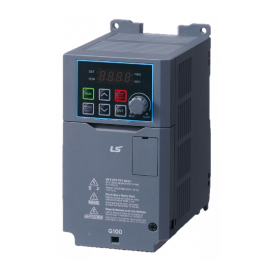
- Page 1 Installation Quick Guide Manual Download For detailed information on installation and commissioning, full version of the G100 manual can be downloaded at www.lsis.com Verify & Identify the Delivery LSLV 0022 G100 • Inspect the drive for any damanage. If the drive appearsdamage upon receipt, contact your supplier.
-
Page 2: Power Terminal Wiring
Description / Factory Default Parameters OU-31 Relay output 1, Default: Trip A1/B1/C1 A2/C2 OU-33 Relay output 2, Default: Run Analog voltage output terminal Default: Output Frequency Switch Description External 24V power source S+/S- RS-485 signal line | LSIS Co., Ltd. -
Page 3: About The Display
Switches from the selected state of parameter to the input state. Edits parameter and apply change. [ENTER] key MODE Accesses the operation information SHIFT screen during failure on the failure screen. Parameter Group and Code Selection Parameter Selection Keypad Monitoring LSIS Co., Ltd. |... -
Page 4: Basic Commissioning
A1 B1 C1 A2 C2 VR V1 I2 A0 CM S+ S- 0 ~ 10 Vdc A1 B1 C1 A2 C2 VR V1 I2 A0 CM S+ S- 4: V0, Built-in pot Potentiometer resistance: 1~5kΩ 2: V1, 0~10V | LSIS Co., Ltd. - Page 5 St-3_Multi-step speed frequency3 speed search feature needs to be activated. bA-53_Multi-step speed frequency4 Group Code Name Function bA-54_Multi-step speed frequency5 _ _1_ Speed search Initialization after bA-55_Multi-step speed frequency6 selection a fault trip (0010) bA-56_Multi-step speed frequency7 LSIS Co., Ltd. |...
- Page 6 Motor Energy saving amount M2 Acceleration time Rotation count speed unit M2 Deceleration time Cooling fan control M2 Base frequency DB unit turn on voltage level Control M2 Rated current Carrier frequency Speed search operation selection | LSIS Co., Ltd.
-
Page 7: Frequently Asked Questions (Faq)
To reduce interference, the installation of noise filters or line filters may be required. Additionally, it may be helpful to adjust the carrier frequency to the minimum value in Cn-04. LSIS Co., Ltd. |... -
Page 8: Troubleshooting Fault Trips
*Latch: Terminates when the reset signals are input after the fault is solved. ■ Head Quarter LS Yongsan Tower, 92, Hangang-daero, Yongsan-gu, Seoul, 04386, Korea Tel: 82-2-2034-4286 E-mail : PLCSales@lsis.com 2019. 05 ⓒ 2019. 05 LSIS Co.,Ltd. All rights reserved. / (01) 2019. 05 Human Power...


Need help?
Do you have a question about the G100 and is the answer not in the manual?
Questions and answers