Chapters
Table of Contents

Related Manuals for Weinmann WM 24042


Summary of Contents for Weinmann WM 24042
- Page 1 -Zuschaltventil Oxygen valve Valve d'adduction d'oxygène WM 24042 Gerätebeschreibung und Gebrauchsanweisung Description and operating instructions Description et mode d'emploi de l'appareil...
- Page 2 Deutsch English Français...
- Page 3 Übersicht Deutsch Zubehör 16 17 Übersicht...
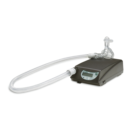
- Page 4 Legende 1 Schlauchhalter 7 Verschlussstopfen 2 Faltenschlauch -Ausgang -Einleitungsschlauch 9 Leuchtdiode -Zuschaltventil 10 Verbindungsleitung 5 Klettstreifen 11 O -Eingang 6 Anschlussbuchse Zubehör 12 Doppelschlauch 13 Faltenschlauch 14 Muffe Faltenschlauch 15 Adapter (klarsichtig) 16 Muffe Adapter 17 Adapter (grau) Legende...
- Page 5 Besondere Kennzeichnungen am Gerät Geräteschild Gerät -Eingang -Ausgang Geräteschild Gerät nicht über Hausmüll entsorgen Schutzklasse B Schutzklasse II, Schutzisolierung Baujahr -Druck max 1,5 bar = 1500 hPa Besondere Kennzeichnungen am Gerät...
- Page 6 Sicherheitshinweise in dieser Anleitung In dieser Gebrauchsanweisung werden die Sicherheitshinweise folgendermaßen gekenn- zeichnet: Warnung! Warnt vor Verletzungsgefahr und möglichen Sachschäden. Vorsicht! Warnt vor Sachschäden und möglicherweise falschen Therapieergebnissen. Hinweis: Enthält nützliche Tipps. Sicherheitshinweise in dieser Anleitung...
-
Page 7: Table Of Contents
Inhalt Gerätebeschreibung ... . . 8 Verwendungszweck ... . 8 Funktionsbeschreibung ..9 Sicherheitshinweise . -
Page 8: Gerätebeschreibung
1. Gerätebeschreibung 1.1 Verwendungszweck Wichtig! Mit dem Sauerstoffzuschaltventil können während der Das O -Zuschaltventil - eben- Therapie bis zu 4 l/min Sauerstoff (O ) in die Maske sicher so wie die Therapiegeräte - eingeleitet werden. Es kann in Verbindung mit einem Sau- verfügt über keinen Alarm, erstoffkonzentrator, einer Sauerstoffflasche mit Druckmin- der vor Störungen warnt. -
Page 9: Funktionsbeschreibung
1.2 Funktionsbeschreibung Das Ventil wird elektrisch mit dem Therapiegerät verbunden und fragt ständig dessen ord- nungsgemäßen Zustand ab. Ist das Therapiegerät eingeschaltet, öffnet sich das innenlie- gende Magnetventil. Dies wird durch eine grüne Leuchtdiode angezeigt. Wenn das Therapiegerät ausgeschaltet ist oder nicht ordnungsgemäß arbeitet, schließt sich das Ventil. Die Kontrollleuchte erlischt. Wird der ordnungsgemäße Zustand wiederhergestellt, öffnet das Ventil wieder. -
Page 10: Sicherheitshinweise
Beachten Sie unbedingt auch die Sicherheitshinweise in der Gebrauchs- anleitung Ihres Sauerstoffsystems! • Lassen Sie Reparaturen nur durch den Hersteller Weinmann durchführen bzw. wenden Sie sich dafür an Ihren Fachhändler. • Bitte beachten Sie zur Vermeidung einer Infektion oder bakteriellen Kon- tamination den Abschnitt „5. - Page 11 • Beim Einsatz von Fremdartikeln kann es zu Funktionsausfällen und einer eingeschränkten Gebrauchstauglichkeit kommen. Außerdem können die Anforderungen an die Bio-Kompatibilität nicht erfüllt sein. Beachten Sie, dass in diesen Fällen jeglicher Anspruch auf Garantie und Haftung erlischt, wenn weder das in der Gebrauchsanweisung empfohlene Zube- hör noch Originalersatzteile verwendet werden.
-
Page 12: Geräteaufstellung
3. Geräteaufstellung 1. Stellen Sie Ihr Therapiegerät und Ihr Sauerstoffsystem auf wie in den zugehörigen Gebrauchsanweisungen beschrieben. Befestigen Sie den O -Einleitungsschlauch mit den Schlauchhaltern an Ihrem Schlauchsystem. 2. Stellen Sie das O -Zuschaltventil so auf, dass Sie die An- schlussleitung und den O -Einleitungsschlauch an- schließen können. - Page 13 6. Stecken Sie den Schlauch Ihres Sauerstoffsystems auf die Eingangsseite des Ventils (große Tülle rechts) 7. Montieren Sie das Ausatemsystem und die Maske ge- mäß den zugehörigen Gebrauchsanweisungen. 8. Entfernen Sie den Verschluss von einem der Druckmes- sanschlüsse an der Maske und stecken Sie dort den O Einleitungsschlauch auf.
-
Page 14: Bedienung
4. Bedienung 4.1 Ein-/Ausschalten des Gerätes Das O -Zuschaltventil ist betriebsbereit, wenn es wie oben beschrieben angeschlossen wur- de. Sie brauchen nur Ihr Therapiegerät und Ihr Sauerstoffsystem (mit dem verordneten Flow) einzuschalten. Das Ventil schaltet die Sauerstoffzufuhr zum Therapiegerät selbsttätig frei und sperrt sie wieder ab. -
Page 15: Hygienische Aufbereitung
5. Hygienische Aufbereitung 5.1 Fristen Das Schlauchsystem je nach Verschmutzung, mindestens jedoch einmal im Monat reinigen. Mindestens alle 6 Monate – bei Verschmutzungen früher – muss der O -Einleitungs- schlauch oder – bei Verwendung des Schlauchsystems mit innenliegendem O -Einleitungs- schlauch –... - Page 16 Reinigung des Schlauchsystems Das Schlauchsystem WM 23737 kann in bis zu 70 °C warmem Wasser gereinigt werden. In den Doppelschlauch darf kein Wasser eindringen. Gehen Sie folgendermaßen vor: 1. Ziehen Sie das Schlauchsystem vom Gerät und vom Verschlussstopfen Ausatemsystem ab. -Einleitungs- 2.
- Page 17 Doppelschlauch entfernen 1. Lösen Sie beide Muffen von den Adaptern. Adapter, grau Doppelschlauch 2. Ziehen Sie den Doppelschlauch aus dem Faltenschlauch heraus. 3. Ziehen Sie den kurzen Teil des Doppelschlauches vom grauen Adapter ab. Ziehen Sie den Schlauch dann aus Muffe dem klarsichtigen Adapter heraus.
-
Page 18: Patientenwechsel
3. Drücken Sie den langen Teil des Doppelschlauches in Adapter, grau die Nut des klarsichtigen Adapters. Die beiden Schlau- Doppelschlauch chenden müssen glatt nebeneinander liegen. 4. Führen Sie das freie Ende des Doppelschlauches in den Faltenschlauch ein. Muffe 5. Schieben Sie die Muffe des Faltenschlauches auf den Muffe klarsichtigen Adapter. -
Page 19: Funktionskontrolle
6. Funktionskontrolle 6.1 Fristen Unterziehen Sie das O -Zuschaltventil täglich einer Funktionskontrolle. Wenn Sie dabei ei- nen Fehler feststellen, dürfen Sie es nicht weiter einsetzen, bevor der Fehler beseitigt ist. 6.2 Durchführung 1. Montieren sie das Ventil funktionsbereit mit dem Therapiegerät. Die Kontollleuchte auf der Oberseite des Ventilgehäuses leuchtet nicht. -
Page 20: Störungen Und Deren Beseitigung
Konzentrators zu gering Liegen Fehler vor, die nicht gleich behoben werden können, setzen Sie sich bitte sofort mit dem Hersteller Weinmann oder Ihrem Fachhändler in Verbindung, um das Ventil instand- setzen zu lassen. Betreiben Sie es nicht weiter, um die mit einer Fehlfunktion verbundene Brandgefahr zu vermeiden. -
Page 21: Wartung
8. Wartung 8.1 Fristen Das Sauerstoffzuschaltventil ist wartungsfrei. Aus hygienischen Gründen empfehlen wir, den O -Einleitungsschlauch bzw. den Doppel- schlauch nach 6 Monaten – bei Verschmutzungen früher – auszutauschen. 8.2 Doppelschlauch wechseln Der Doppelschlauch besteht aus einem kurzen Teil, der für die die Druckmessung während der Therapie verwendet wird und einem langen Teil, der für die O -Einleitung verwendet wird. -
Page 22: Entsorgung
8.3 Entsorgung Entsorgen Sie das Gerät nicht über den Hausmüll. Für die fachgerechte Entsor- gung des Gerätes wenden Sie sich an einen zugelassenen, zertifizierten Elektro- nikschrottverwerter. Dessen Adresse erfragen Sie bei Ihrer/Ihrem Umweltbeauftragten oder Ihrer Stadtverwaltung. Die Geräteverpackung (Papp- karton und Einlagen) können Sie als Altpapier entsorgen. Wartung... -
Page 23: Lieferumfang
9. Lieferumfang 9.1 Serienmäßiger Lieferumfang Sauerstoffzuschaltventil, verpackt WM 24042 Teile Bestellnummer Sauerstoffzuschaltventil, Grundgerät WM 24102 -Einleitungsschlauch WM 24015 6 x Schlauchhalter WM 24268 Klettstreifen zur Befestigung WM 24687 Gebrauchsanweisung WM 16792 9.2 Ersatzteile Teile Bestellnummer -Einleitungsschlauch WM 24015 Klettstreifen zur Befestigung WM 24687 9.3 Zubehör... -
Page 24: Technische Daten
10. Technische Daten Produktklasse nach 93/42/EWG Abmessungen BxHxT in cm 4,5 x 8,5 x 3,0 Gewicht ca. 123 g Temperaturbereich – Betrieb +5 °C bis +40 °C – Lagerung –20 °C bis +70 °C Luftdruckbereich 700 – 1060 mbar zul. Feuchtigkeit bei Betrieb und Lagerung ≤95 % rF (keine Betauung) Elektrischer Anschluss 7–15 V DC... -
Page 25: Garantie
Vorsatz oder grober Fahrlässigkeit beruhen oder bei leicht fahrlässiger Verletzung von Leib oder Leben. • Weinmann behält sich das Recht vor, nach seiner Wahl den Mangel zu beseitigen, eine mangelfreie Sache zu liefern oder den Kaufpreis ange- messen herabzusetzen. •... -
Page 26: Konformitätserklärung
12. Konformitätserklärung Hiermit erklärt die Weinmann Geräte für Medizin GmbH + Co. KG, dass das Produkt den einschlägigen Bestimmungen der Richtlinie 93/42/EWG für Medizinprodukte entspricht. Den vollständigen Text der Konformitätserklärung finden Sie unter: www.weinmann.de Konformitätserklärung... -
Page 27: Stichwortverzeichnis
13. Stichwortverzeichnis Anfeuchtung Aufstellung Desinfektion Ersatzteile Funktionskontrolle Garantie Kennzeichnungen Reinigung Sicherheitshinweise Störungen Zubehör Stichwortverzeichnis... - Page 28 Overview English Accessory 16 17 Overview...
- Page 29 Legend 1 Hose holder 7 Plug 2 Corrguated hose outlet supply hose 9 LED 4 Oxygen valve 10 Connecting cable 5 Velcro strips 11 O inlet 6 Socket Accessory 12 Double hose 13 Corrguated hose 14 Sleeve for corrugated hose 15 Adapter (transparent) 16 Sleeve for adapter 17 Adapter (grey)
- Page 30 Special marks on the device Rating plate Unit Unit inlet Unit outlet Rating plate Do not dispose of the unit in domestic waste! Protection class B Protection class II, protective insulation Year of manufacture -pressure max 1.5 bar = 1500 hPa Special marks on the device...
- Page 31 Safety information in these instructions Safety information is marked as follows in these instructions for use: Warning! Warns of a risk of injury and potential material damage. Caution! Warns of material damage and potentially false therapy results. Note Contains useful tips. Safety information in these instructions...
- Page 32 Contents Description ....33 Purpose ....33 Functional description .
-
Page 33: Description
1. Description 1.1 Purpose Important: During therapy the oxygen valve can be used to safely sup- Like the therapy devices, the ply up to 4 l/min oxygen into the mask. It can be used to- oxygen valve does not have gether with an oxygen concentrator, an oxygen cylinder an alarm that warns in the with a pressure reducing valve or liquid oxygen. -
Page 34: Functional Description
1.2 Functional description The valve is electrically connected with the therapy device and scans the latter constantly to ensure it is working correctly. If the therapy device is switched on, the internal solenoid valve opens. This is indicated by a green LED. If the therapy device is switched off or does not work prop- erly, the valve closes. -
Page 35: Safety Instructions
Always follow the safety instructions in the instruction manual supplied with your oxygen system. • Have repairs carried out only by the manufacturer Weinmann or refer to your dealers for repairs. • Please follow section “5. Hygienic preparation” on page 39 to prevent infection or bacterial contamination. -
Page 36: Setting Up The Device
3. Setting up the device 1. Set up your therapy device and oxygen system as de- scribed in the relevant instruction manuals. Secure the supply hose to your hose system with the hose hold- ers. 2. Put the oxygen valve in a position so that you can con- nect the connecting cable and the O supply hose. - Page 37 6. Insert the hose from your oxygen system onto the inlet side of the valve (large scket on the right) 7. Assemble the exhalation system and the mask according to the relevant instruction manuals. 8. Remove the seal from the port on the mask and attach the O supply hose there.
-
Page 38: Operation
4. Operation 4.1 Switching the device on and off The oxygen valve is ready for use when it has been connected as described above. You sim- ply have to switch on your therapy device and your oxygen system (with the prescribed fl ow). -
Page 39: Hygienic Preparation
5. Hygienic preparation 5.1 Intervals Clean the hose system whenever it is dirty or at least once a month. The O supply hose has to be changed at least every six months or earlier if it’s soiled. (If a hose system is used, the internal O supply hose has to be replaced according to this schedule (see “8.2 Chan- ging the double hose”... - Page 40 5. Rinse the creased tube thoroughly inside and out with clear warm water. 6. Thoroughly shake out the tube system. 7. Hang up the tube system and allow it to drip dry, in order to prevent moisture entering your therapy device. 8.
-
Page 41: Changing Patients
Disinfect creased tube and adapter 1. Proceed as described in “Clean the tube system”. 2. After disinfecting, rinse thoroughly with distilled water. Fit double tube 1. Push the short part of the double tube through the transparent adapter and then push it as far as possible onto the gray adapter. -
Page 42: Performance Check
6. Performance check 6.1 Intervals Check daily that the oxygen valve works properly. If you detect a fault, do not continue to use it until the fault has been remedied. 6.2 Method 1. Assemble the valve so that it works with the therapy device. The control lamp on the top of the valve housing does not light up. -
Page 43: Troubleshooting
(e.g., OXYMAT) In the event of any faults that cannot be remedied immediately, contact the manufacturer Weinmann or your dealer immediately to have the valve repaired. Do not continue to use it because a fault may increase the risk of fire. -
Page 44: Maintenance
8. Maintenance 8.1 Intervals The oxygen valve requires no maintenance. For hygienic reasons, we recommend replacing the O supply hose or the double hose after six months, or earlier if it is soiled. 8.2 Changing the double hose The double tube consists of a short part which is used for pressure measurement during therapy, and a long part that is used for O supply. -
Page 45: Waste Disposal
8.3 Waste disposal To dispose of the unit properly, please contact a licensed and certified electronic waste disposal merchant. Names and addresses can be obtained from your Envi- ronmental Officer or municipal authorities. The unit packaging (cardboard box and inserts) can be disposed of as waste paper. Maintenance... -
Page 46: Supply Schedule
9. Supply Schedule 9.1 Standard supply schedule Oxygen valve, packed WM 24042 Part Order No. Oxygen valve, Basic unit WM 24102 supply hose WM 24015 6 hose holders WM 24268 Velcro strips for fastening WM 24687 Instruction manual WM 16792 9.2 Spare parts... -
Page 47: Technical Specifications
10. Technical specifications Product class in compliance with 93/42/EEG Dimensions (W x H x D) in cm 4.5 x 8.5 x 3.0 Weight approx. 123 g Temperature range – Operation +5 °C to +40 °C – Storage –20 °C to +70 °C Air pressure range 700 –... -
Page 48: Warranty
– Failure to use original spare parts • Weinmann is not liable for consequential harm caused by a defect if it is not based on intention or gross negligence. Weinmann is also not liable for minor physical injury to life or limb resulting from negligence. -
Page 49: Declaration Of Conformity
12. Declaration of Conformity Weinmann Geräte für Medizin GmbH + Co. KG declares herewith that the product com- plies fully with the respective regulations of the Medical Device Directive 93/42/EEC. The unabridged text of the Declaration of Conformity can be found on our website at www.weinmann.de... -
Page 50: Index
13. Index Accessories Cleaning Disinfection Faults Humidification Performance check Safety instructions Set up Spare parts Special marks on the device Warranty Index... - Page 52 Vue d´ensemble Français Accessoire 16 17 Vue d´ensemble...
- Page 53 Légende 1 Fixations tuyaux 7 Bouchon de fermeture 2 Tube à soufflets 8 Sortie O 3 Tuyau d´alimentation en O 9 Diode lumineuse 4 Valve d'adduction d'oxygène 10 Câble de raccordement 5 Bande de montage 11 Entrée O 6 Fiche de connexion Accessoire 12 Double tube 13 Tube à...
- Page 54 Repères particuliers sur l’appareil Plaque signalétique Appareil Entrée O Sortie de l’appareil Plaque signalétique Ne pas éliminer l‘appareil avec les ordures ménagères ! Classe de protection B Classe de protection II, isolation de protection Année de construction Pressure O max. 1,5 bar = 1500 hPa Repères particuliers sur l’appareil...
- Page 55 Consignes de sécurité données dans ce mode d'emploi Les consignes de sécurité figurant dans ce mode d'emploi se présentent comme suit : Attention ! Met en garde lorsqu'il existe un risque de blessures ou de dommages matériels. Prudence ! Met en garde lorsqu'il existe un risque de dommages matériels et d'obtention de ré- sultats erronés.
- Page 56 Sommaire Description de l‘appareil ..57 Domaine d’utilisation ..57 Description du fonctionnement . . 58 Consignes de sécurité ... 59 Exigences de sécurité...
-
Page 57: Description De L'appareil
1. Description de l‘appareil 1.1 Domaine d’utilisation Important ! La valve d'adduction d'oxygène permet d’envoyer de fa- La valve d'adduction d'oxygè- çon sûre jusqu’à 4 l d’oxygène (O ) par minute dans le ne – tout comme les appareils masque durant le traitement. Elle peut être utilisée en de traitement –... -
Page 58: Description Du Fonctionnement
La vanne s’ouvre lorsque l’appareil de traitement est sous tension et fonctionne correctement. Dans le cas d’un dys- fonctionnement (par ex. une panne de courant), l’alimen- tation en oxygène est interrompue afin d’éviter un enrichissement en O dans l’appareil et donc de prévenir de façon sûre un risque d’incendie dû... -
Page 59: Consignes De Sécurité
Respectez aussi strictement les consignes de sécurité données dans le mode d'emploi de votre système d'alimentation en oxygène ! • Faites exécuter toutes les réparations par le constructeur, Weinmann, ou adressez-vous à votre revendeur agréé. • Pour prévenir toute infection ou contamination bactérienne, observez les consignes données dans le chapitre «... - Page 60 • L'utilisation d'articles d'autres marques peut être à l'origine de dysfonctionnements et compromettre l'usage de l'appareil. Il est possible en outre que les exigences de biocompatibilité ne soient pas satisfaites. Veuillez noter que nous déclinons toute responsabilité et n'accordons aucune garantie lorsque ni les accessoires conseillés dans le mode d'emploi, ni des pièces de rechange originales ne sont utilisés.
-
Page 61: Installation De L'appareil
3. Installation de l’appareil 1. Installez votre appareil de traitement et votre système à oxygène comme décrit dans les modes correspondants. Fixez le tuyau d’alimentation en O à votre circuit pa- tient à l’aide des fixations tuyau. 2. Installez la valve d'adduction O de sorte que le câble de raccordement et le tuyau d’alimentation en O puis-... - Page 62 6. Montez le tube de votre système à oxygène sur le côté entrée de la vanne (grande douille à droite) 7. Montez le système expiratoire et le masque conformément aux modes d'emploi correspondants. 8. Retirez le bouchon de fermeture d’un des raccords de pression du masque et connectez-y le tuyau d’alimen- tation en O 9.
-
Page 63: Utilisation
4. Utilisation 4.1 Mise en marche/arrêt de l‘appareil La valve d'adduction O est prête à fonctionner si elle a été raccordée comme décrit ci-des- sus. Il vous suffit de connecter votre appareil de traitement et votre système à oxygène (avec le débit prescrit). La vanne libère automatiquement l’alimentation en oxygène vers l’appareil de traitement et la verrouille à... -
Page 64: Préparation Hygiénique
5. Préparation hygiénique 5.1 Intervalles Nettoyez le circuit patient lorsqu’il est sale et au moins une fois par mois. Remplacez tous les six mois – plus tôt s’il est sale – le tuyau d’alimentation en O (si vous utilisez le circuit patient, le tuyau d’alimentation en O intérieur (voir «... - Page 65 1. Séparez les tuyaux de l'appareil et du circuit expiratoire. Obturateurs 2. Tirez un peu le double tuyau hors du tuyau annelé. Tuyau d'injection O Bouchez l’orifice à l’aide de l’obturateur fourni avec l’appareil. 3. Bouchez le petit orifice de l'adaptateur gris et le tuyau d'injection d'O à...
- Page 66 Désinfection du double tuyau 1. Fermez les quatre orifices du double tuyau à l’aide des obturateurs fournis avec l’appareil. 2. Nettoyez à fond le double tuyau à l'eau chaude addi- tionnée d'un peu de désinfectant. 3. A l'issue de la désinfection, rincez le double tuyau exté- rieurement à...
-
Page 67: Changement De Patient
5.3 Changement de patient Dans le cas d’un changement de patient, le tuyau d’alimentation en O ou le circuit patient doivent être remplacés et la vanne d’adduction O doit être nettoyée en l’essuyant avec une solution désinfectante. Préparation hygiénique... -
Page 68: Contrôle De Fonctionnement
6. Contrôle de fonctionnement 6.1 Intervalles Soumettez la valve d'adduction O à un contrôle de fonctionnement quotidien. Si vous constatez des erreurs lors du contrôle de fonctionnement, ne remettez pas l’appareil en service avant d’y avoir remédié. 6.2 Procédure 1. Montez la vanne prête à fonctionner sur l’appareil de traitement. Le témoin de contrôle sur le dessus du boîtier de la vanne ne s’allume pas. -
Page 69: Pannes Et Leur Élimination
(par ex. OXYMAT) S’il survient des pannes auxquelles il n’est pas possible de remédier immédiatement, ren- voyez l’appareil au fabricant Weinmann ou déposez-le chez votre revendeur spécialisé pour remettre la vanne en état. Ne continuez pas à utiliser la vanne afin d’éviter tout risque d’incendie lié à un dysfonction- nement. -
Page 70: Entretien
8. Entretien 8.1 Intervalles La valve d'adduction O ne requiert aucun entretien. Pour des raisons d’hygiène, nous vous recommandons de remplacer le tuyau d’alimenta- tion en O ou le double tube tous les six mois – plus tôt s’il est sale. 8.2 Remplacement du double tube Le double tuyau est constitué... -
Page 71: Élimination
8.3 Élimination Ne pas éliminer l'appareil avec les ordures ménagères ! Pour assurer l’élimination dans les règles de l'art, adressez-vous à une entreprise d'élimination des déchets agréée et certifiée. Des adresses vous seront communiquées par le responsable des questions d'environnement ou par les services municipaux. L'emballage de l'appa- reil (carton et éléments de séparation) peut être recyclé... -
Page 72: Étendue De La Fourniture
9. Étendue de la fourniture 9.1 Fourniture de série Valve d'adduction O , emballée WM 24042 Pièces Numéros de référence Valve d'adduction O , Appareil de base WM 24102 Tuyau d’alimentation en O WM 24015 6 x fixations tuyau WM 24268... -
Page 73: Caractéristiques Techniques
10. Caractéristiques techniques Classe de produit selon 93/42/CEE Dimensions l x h x p en cm 4,5 x 8,5 x 3,0 Poids environ 123 g Plages de température – Fonctionnement de +5 °C à +40 °C – Stockage de –20 °C à +70 °C Plage de pression 700 –... -
Page 74: Garantie
11. Garantie • A compter de la date d’achat, Weinmann garantit pour une période de 2 ans et dans des conditions normales d’utilisation que le produit ne pré- sente pas de défauts. Pour les produits ayant une durée de validité infé- rieure à... -
Page 75: Déclaration De Conformité
12. Déclaration de conformité La société Weinmann Geräte für Medizin GmbH + Co. KG, déclare par la présente que le produit est conforme aux dispositions respectives de la Directive européenne 93/42/CEE re- lative aux dispositifs médicaux. Le texte intégral de la déclaration de conformité est dispo- nible sur Internet à... -
Page 76: Index
13. Index Accessoires Anomalies Consignes de sécurité Contrôle de fonctionnement Désinfection Funktionskontrolle Garantie Humidification Installation Nettoyage Pannes Pièces de rechange Repères particuliers sur l’appareil Index... - Page 80 Weinmann Geräte für Medizin GmbH+Co.KG P.O.Box 540268 • D-22502 Hamburg Kronsaalsweg 40 • D-22525 Hamburg T: +49-(0)40-5 47 02-0 F: +49-(0)40-5 47 02-461 E: info@weinmann.de www.weinmann.de Center for Production, Logistics, Service Weinmann Geräte für Medizin GmbH+Co.KG Siebenstücken 14 D-24558 Henstedt-Ulzburg...
Need help?
Do you have a question about the WM 24042 and is the answer not in the manual?
Questions and answers