Table of Contents
Advertisement
Available languages
Available languages
Quick Links
INSTALLATION & OPERATING INSTRUCTIONS
1595CFKV2 CIRCULATING FAN KIT
Use with Valor models 1500K, 1700K and 1800K Linear Fireplaces
WARNING
If these instructions are not followed
exactly, a fire or explosion may result
causing property damage, personal
injury or loss of life.
GROUNDING: The power supply for this accessory must be installed and grounded in
accordance with local codes, or in the absence of local codes, with the current Canadian
Electrical Code CSA C22.1. or in the USA the National Electrical Code ANSI/NFPA70 latest
edition.
Description of System
The models 1500, 1700 and 1800 fireplaces have been
designed to accommodate the installation of an optional
150CFM air circulation fan. The fan is designed to boost
the natural convection through the heater; this may be
a desirable feature dependent on the fireplace location
and room layout.
It is preferable to install the circulating fan before
completing the heater installation although it may
also be retrofitted at a later date provided the power re-
ceptacle has been prewired within the fireplace casing.
Retrofitting the fan after the fireplace installation is com-
pleted will require disconnecting the gas and removing
the burner module and gas train from the fireplace.
The fan is designed for automatic operation to come ON
and OFF when the burner comes ON and turns OFF. The
fan speed can be controlled from the remote control
handset. There are four speeds available.
The fan, if turned ON, will start approximately 4 minutes
after lighting the appliance and will continue to run for
approximately 10 minutes after the burner is shut off.
The fan will operate at the speed last selected by the
user.
Future servicing or replacement of the fan may be done
through the window aperture of the fireplace without
needing to remove the fireplace from the wall cavity.
4007879-01
© 2019, Miles Industries Ltd. All rights reserved.
Linear
Note: This kit must be installed or serviced
by a qualified installer, service agency
or gas supplier. These instructions are
to be used in conjunction with the main
installation instructions for the above
listed models.
NOTICE
A control module GV60VM—V-Module kit
(sold separately) is required to provide
power and speed control to the fan. The
V-Module plugs into a receptacle located
within the fireplace. Ensure power is
provided to the receptacle. See Electrical
Wiring section in fireplace installation
manual for details.
Electrical Requirements
This optional fan kit connects to a control module (sold
separately) to be mounted within the fireplace casing.
The fan electrical requirements are 120 Volts, 1 phase,
60 Hz. Full load current of less than 1 amp.
Please leave this manual with the homeowner.
1
Advertisement
Table of Contents

Related Manuals for Valor 1595CFKV2


Summary of Contents for Valor 1595CFKV2
- Page 1 INSTALLATION & OPERATING INSTRUCTIONS Linear 1595CFKV2 CIRCULATING FAN KIT Use with Valor models 1500K, 1700K and 1800K Linear Fireplaces Note: This kit must be installed or serviced WARNING by a qualified installer, service agency If these instructions are not followed or gas supplier.
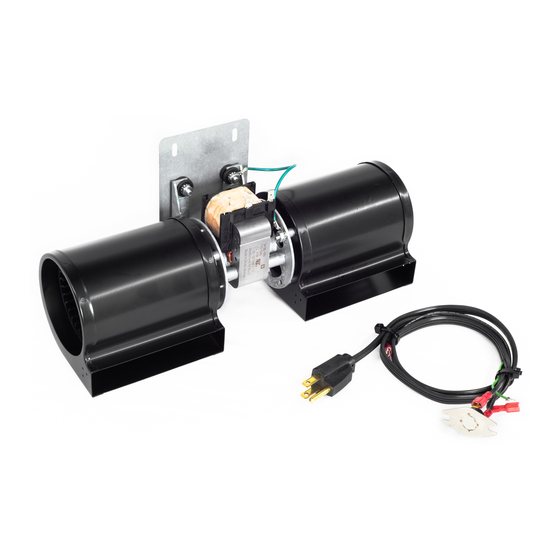
- Page 2 Installation Components Required 1595CFKV2—Circulating Fan Kit, containing: • Fan unit (motor and housing) • Fan mounting plate • Thermal switch • Power cable with Molex connector Fan mounting plate Fan unit • Wiring diagram label Sheet metal • Sheet metal screws (2)
- Page 3 To install the fan 1. Insert the fan through the opening in the floor of the firebox and rotate into position. Operation with Valor 10 Remote Control To operate the fan, press the button on the remote handset; the fan icon flashes on the display.
- Page 4 1700 / 1800 J or K appliances: Remove the plate to 4. Plug the control module into the receiver. the right of the opening to access fixing points for the fan (4 screws). Remove fan fixing access plate (4 screws) 2.
-
Page 5: Spares List
Part Numbers of liner box Blower 4000537 Fan Mounting Bracket 4003053 3-pin Molex Power cord, 37” long 4007877 Thermal Switch 4003065 Cable, Switch to Motor, 10” 4003067 Ground cable, eyelet each end 4003068 Clamp Self Adhesive 4000536 Schematic label 1595CFKV2 4007878... -
Page 6: Wiring Diagram
Limited warranty policy Miles Industries Ltd. warrants all components of the model 1595CFKV2 Circulating Fan Kit for a period of one year from the date of purchase against defects in materials or workmanship. This warranty covers only the cost of defective parts and applies only to the original consumer purchaser. -
Page 7: Description Du Système
GUIDE D’INSTALLATION ET D’OPÉRATION Linear VENTILATEUR DE CIRCULATION D’AIR 1595CFKV2 Utilisez avec les foyers Valor Linears 1500K, 1700K et 1800K AVERTISSEMENT Note : Cette trousse doit être installée et entretenue par un installateur qualifié, Si les instructions fournies dans le une agence de service certifiée ou un... - Page 8 Pièces requises pour l’installation Ventilateur de circulation d’air 1595CFKV2, contenant : • Boîtier du ventilateur (moteur et boîtier) • Plaque de montage • Interrupteur thermique Plaque de montage Ventilateur • Cordon d’alimentation à Molex Vis à métaux • Schéma des connexions...
- Page 9 Pour installer le ventilateur 1. Insérez le ventilateur dans l’ouverture au fond de la boîte de foyer et pivotez-le en position. Opération avec télécommande Valor 10 Pour allumer le ventilateur, appuyez sur sur la télécommande; l’icône clignotera sur l’écran.
- Page 10 Foyers 1700 / 1800 J ou K : Enlevez la petite plaque à 4. Branchez le module de commande dans le récepteur. la droite de l’ouverture principale pour accéder aux points de fixation du ventilateur (4 vis). Enlevez la plaquette d’accès pour fixer le ventilateur (4 vis) 2.
-
Page 11: Pièces De Remplacement
Plaque de montage 4003053 Cordon d’alimentation à connecteur 4007877 Molex, 37” de long Interrupteur thermique 4003065 Câble, Interrupteur au moteur, 10” 4003067 Câble mise à la terre, oeillet à chaque bout 4003068 Serre-fi l auto-collant 4000536 Schéma des connexions 1595CFKV2 4007878... -
Page 12: Schéma Des Connexions
INTERRUPTEUR THERMIQUE CONNECTEUR MOLEX 3 FICHES, BOÎTE DE RACCORDEMENT 37” DE LONG #4007877 DANS LE FOYER MISE À TERRE MODÈLE 1595CFKV2 VENTILATEUR DE CIRCULATION D’AIR 120 VAC, 60 HZ, MOINS D’UN AMPÈRE NOIR FABRIQUÉ POUR BLANC MILES INDUSTRIES LTD NORTH VANCOUVER, CANADA...
Need help?
Do you have a question about the 1595CFKV2 and is the answer not in the manual?
Questions and answers