Table of Contents
Advertisement
Quick Links
Advertisement
Table of Contents

Related Manuals for Freescale Semiconductor NXP CodeWarrior USB TAP


Summary of Contents for Freescale Semiconductor NXP CodeWarrior USB TAP
- Page 1 CodeWarrior™ USB TAP Users Guide Revised: 11 November 2005...
- Page 2 Semiconductor makes no warranty, representation or guarantee regarding the suitability of its products for any partic- ular purpose, nor does Freescale Semiconductor assume any liability arising out of the application or use of any product or circuit, and specifically disclaims any and all liability, including without limitation consequential or incidental dam- ages.
-
Page 3: Table Of Contents
Table of Contents Introducing the CodeWarrior™ USB TAP Emulator What is the USB TAP Emulator? ........5 Product Highlights. - Page 4 Table of Contents USB TAP Specifications ......... . .19 Electrical Characteristics .
-
Page 5: Introducing The Codewarrior™ Usb Tap Emulator
Introducing the CodeWarrior™ USB TAP Emulator The CodeWarrior USB TAP emulator is a cost-effective tool that helps you develop and debug a number of processors and microcontrollers. This chapter introduces you to the USB TAP emulator. The sections are: • What is the USB TAP Emulator? •... -
Page 6: Product Highlights
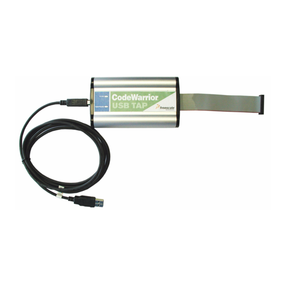
Introducing the CodeWarrior™ USB TAP Emulator What is the USB TAP Emulator? Figure 1.1 USB TAP for ARM®JTAG with USB 2.0 Cable Product Highlights The USB TAP emulator has these features: • Supports the following systems: PowerPC™ processors, ARM® processors, ColdFire™... -
Page 7: The Debugging Environment
Introducing the CodeWarrior™ USB TAP Emulator What is the USB TAP Emulator? • Automatically supports target signal levels from 1.8V to 3.3V. • Software debug capabilities including: – Controlling instruction execution. – Display and modify target memory. – Examine and modify any processor registers. –... -
Page 8: Operating Requirements
Introducing the CodeWarrior™ USB TAP Emulator Operating Requirements Operating Requirements Before setting up your system, you should make sure that the operating environment is prepared. Standard Electrostatic Precautions This instrument contains static-sensitive components that are subject to damage from electrostatic discharge. Use standard ESD precautions when transporting, handling, or using the instrument and the target, when connecting/disconnecting the instrument and the target, and when removing the cover of the instrument. -
Page 9: Target Requirements
Introducing the CodeWarrior™ USB TAP Emulator Related Documentation Target Requirements The USB TAP emulator automatically supports target signal levels from 1.8V to 3.3V. NOTE In the case of the PowerPC, for the USB TAP emulator to properly stop and restart a JTAG/COP target processor, the QACK signal must be pulled low. The USB TAP emulator pulls this signal low through the JTAG/COP connector. - Page 10 Introducing the CodeWarrior™ USB TAP Emulator Related Documentation USB TAP Users Guide...
-
Page 11: Connecting To The Target And Your Host Computer
Connecting to the Target and your Host Computer To test your software using the USB TAP emulator, you must have working target hardware. This chapter explains how to connect the USB TAP emulator to such hardware and to your host computer. The sections are: •... -
Page 12: Target Connection
Connecting to the Target and your Host Computer Target Connection Target Connection CAUTION Failure to properly connect the USB TAP emulator to the target may damage the USB TAP emulator or target. Verify all connections before applying power. If your target system has a debug port header, you can directly connect the USB TAP emulator to the target debug port header. -
Page 13: Setting The Debug Port Clock Frequency
Connecting to the Target and your Host Computer Setting the Debug Port Clock Frequency Setting the Debug Port Clock Frequency The debug port on your target is a synchronous interface clocked by the TCK or DSCK signal. The base frequency is set by the debugger and can be adjusted with preferences in the debugger. - Page 14 Connecting to the Target and your Host Computer What To Do Next USB TAP Users Guide...
-
Page 15: Using The Usb Tap
Using the USB TAP This chapter provides system startup procedures, explains how the USB TAP works and provides important information about using the system. The sections are: • USB TAP System Startup • Notes on Using the USB TAP USB TAP System Startup This section explains how to start using the USB TAP and the debugger. -
Page 16: Run/Pause/Mixed Mode States
Using the USB TAP USB TAP System Startup Run/Pause/Mixed Mode States When the host debugger is connected to the target via the USB TAP, the USB TAP is always in one of these states (modes): run, pause or mixed mode. •... -
Page 17: Hardware Specifications
Hardware Specifications This chapter provides hardware specifications for the USB TAP emulator. The sections are: • Connectors and LEDs • USB TAP Specifications Connectors and LEDs Figure 4.1 Figure 4.2 show the various LEDs and connectors of the USB TAP device. Figure 4.1 USB TAP Device—Top View Transmit/Receive LED Debug port connector... -
Page 18: Run/Pause Indicator
Hardware Specifications Connectors and LEDs These topics explain the various LEDs and connectors on the USB TAP device: • Run/Pause Indicator • Transmit/Receive Indicator • USB Connector • Debug Port Connector Run/Pause Indicator The USB TAP hardware has a status LED labeled Run/Pause. It indicates the state of execution on the target device as follows: •... -
Page 19: Debug Port Connector
Hardware Specifications USB TAP Specifications Debug Port Connector The debug connector consists of a 5.5 inch ribbon cable with the appropriate debug connector attached. The ribbon cable has a red stripe down one side to indicate the location of pin 1. NOTE The OnCE connector is equipped with a removable plug in pin 8. -
Page 20: Physical Considerations
Hardware Specifications USB TAP Specifications Physical Considerations The USB TAP was carefully designed to be as small as possible. Even so, it may not physically fit in all target systems. Contact Freescale if you have any special considerations that need review. Table 4.1 shows the physical characteristics of the USB TAP. -
Page 21: A Jtag/Cop Connector Information
JTAG/COP Connector Information The CodeWarrior USB TAP for JTAG/COP has a 16-pin connector. The CodeWarrior USB TAP for JTAG/COP automatically supports target signal levels from 1.8V to 3.3V. Figure A.1 shows the pin assignments of the CodeWarrior USB TAP for JTAG/COP connector. - Page 22 JTAG/COP Connector Information Table A.1 CodeWarrior USB TAP for JTAG/COP Signal Directions JTAG/ Signal Signal Description Mnemonic Direction From target 30pF load QACK From USB 100Ohm pull-down connector From USB 50mA driver connector TRST From USB 50mA driver connector HALTED Bi-directional Open-drain, 100Ohm to ground when asserted by USB TAP emulator, 35pF load...
- Page 23 JTAG/COP Connector Information Table A.1 CodeWarrior USB TAP for JTAG/COP Signal Directions ( continued ) JTAG/ Signal Signal Description Mnemonic Direction HRST Bi-directional Open-drain. 100Ohm to ground when asserted by USB TAP, 35pF load when not asserted No Connect - n/a - CKSO From target 30pF load...
- Page 24 JTAG/COP Connector Information Table A.2 CodeWarrior USB TAP for JTAG/COP Signal Recommendations/Requirements JTAG/ Signal Requirement Mnemonic TRST Must be wired to the target processor. The USB TAP emulator drives the TRST output with up to 50mA. To gain control of the processor, the USB TAP emulator negates TRST approximately 250 milliseconds before negation of HRST.
- Page 25 JTAG/COP Connector Information Table A.2 CodeWarrior USB TAP for JTAG/COP Signal Recommendations/Requirements JTAG/ Signal Requirement Mnemonic HRST Must be wired to the target processor. During reset, the USB TAP drives HRST to ground through a 100Ohm resistor. No Connect Not required for emulation CKSO Should be wired to the target processor.
- Page 26 JTAG/COP Connector Information USB TAP Users Guide...
-
Page 27: B Dpi Connector Information
DPI Connector Information The USB TAP for DPI has a 10-pin connector. The CodeWarrior USB TAP for DPI automatically supports target signal levels from 1.8V to 3.3V. Figure B.1 shows the pin assignments of the CodeWarrior USB TAP for DPI connector. Table B.1 lists DPI signal names, direction, pin numbers, descriptions, and drive capabilities for the USB TAP DPI Connector. - Page 28 DPI Connector Information Table B.1 CodeWarrior USB TAP Emulator for DPI Signal Directions Signal Signal Description Mnemonic Direction VLSO/FRZ From target 30pF load SRST Bi-directional Open-drain. 100Ohm to ground when asserted by USB TAP, 35pF load when not asserted - n/a - DSCK From USB TAP 50mA driver...
- Page 29 DPI Connector Information Table B.2 CodeWarrior USB TAP for DPI Signal Recommendations and Requirements Signal Requirement Mnemonic DSCK Must be wired to the target processor. It is driven by the USB TAP as an output with up to 50mA. This signal is the clock for the DPI interface.
- Page 30 DPI Connector Information USB TAP Users Guide...
-
Page 31: C Bdm Connector Information
BDM Connector Information The USB TAP for BDM has a 26-pin connector. The CodeWarrior USB TAP for BDM automatically supports target signal levels from 1.8V to 3.3V. Figure C.1 shows the pin assignments of the CodeWarrior USB TAP for BDM connector. Table C.1 lists BDM signal names, direction, pin numbers, descriptions, and drive capabilities for the USB TAP BDM Connector. - Page 32 BDM Connector Information Figure C.1 CodeWarrior USB TAP for BDM Connector Pin Assignments Reserved BKPT DSCLK Reserved RESET PST3 PST2 PST1 PST0 DDATA3 DDATA1 DDATA2 DDATA0 Reserved Reserved PSTCLK Core Voltage To connect the CodeWarrior USB TAP for BDM connector to a BDM header: 1.
- Page 33 BDM Connector Information Table C.1 CodeWarrior USB TAP Emulator for BDM Signal Directions Signal Signal Description Mnemonic Direction Reserved From target 30pF load BKPT Bi-directional Open-drain. 100Ohm to ground when asserted by USB TAP, 35pF load when not asserted - n/a - DSCLK From USB TAP 50mA driver...
- Page 34 BDM Connector Information Table C.1 CodeWarrior USB TAP Emulator for BDM Signal Directions ( continued ) Signal Signal Description Mnemonic Direction - n/a - Reserved - n/a - Reserved - n/a - - n/a - PSTCLK From target 30pF load Core Voltage - n/a - From USB TAP...
- Page 35 BDM Connector Information Table C.2 CodeWarrior USB TAP for BDM Signal Recommendations and Requirements Signal Requirement Mnemonic RESET Must be wired to the target. During reset, the USB TAP drives RESET to ground through a 100Ohm resistor. Must be wired to the target processor. The USB TAP emulator drives the TDI output with up to 50mA.
- Page 36 BDM Connector Information Table C.2 CodeWarrior USB TAP for BDM Signal Recommendations and Requirements Signal Requirement Mnemonic Reserved Need not be wired to the target. The USB TAP does not currently use this signal. Reserved Need not be wired to the target. The USB TAP does not currently use this signal.
-
Page 37: D Once Connector Information
OnCE Connector Information The CodeWarrior USB TAP for OnCE has a 14-pin connector. The CodeWarrior USB TAP for OnCE automatically supports target signal levels from 1.8V to 3.3V. Figure D.1 shows the pin assignments of the CodeWarrior USB TAP for OnCE connector. Table D.1 lists OnCE signal names, direction, pin numbers, descriptions, and drive capabilities for the CodeWarrior USB TAP for OnCE Connector. - Page 38 OnCE Connector Information Table D.1 CodeWarrior USB TAP for OnCE Signal Directions OnCE Signal Signal Description Mnemonic Direction From USB TAP 50mA driver connector - n/a - From target 30pF load - n/a - From USB TAP 50mA driver connector - n/a - Reserved From USB TAP...
- Page 39 OnCE Connector Information Table D.2 CodeWarrior USB TAP for OnCE Signal Recommendations and Requirements OnCE Signal Requirement Mnemonic Must be wired to the target processor. The USB TAP emulator drives the TDI output with up to 50 mA. The TDI trace should be kept short and maintain a "two-signal-width"...
- Page 40 OnCE Connector Information Table D.2 CodeWarrior USB TAP for OnCE Signal Recommendations and Requirements OnCE Signal Requirement Mnemonic Must be wired to the target. The USB TAP emulator uses this signal to determine if power is applied to the target. This signal is also used as a voltage reference for the signals driven by the USB TAP emulator (TDI, TCK, TMS, RESET, and TRST).
-
Page 41: E Arm® Jtag Connector Information
ARM® JTAG Connector Information The CodeWarrior USB TAP for ARM® JTAG has a 20-pin connector. The CodeWarrior USB TAP for ARM® JTAG automatically supports target signal levels from 1.8V to 3.3V. Figure E.1 shows the pin assignments of the CodeWarrior USB TAP for ARM® JTAG. Table E.1 lists ARM®... - Page 42 ARM® JTAG Connector Information Figure E.1 CodeWarrior USB TAP for ARM® JTAG Connector Pin Assignments VTREF VSUPPLY TRST RTCK SRST DBGRQ DBGACK Table E.1 CodeWarrior USB TAP for ARM® JTAG Signal Directions ARM® Signal Signal Description JTAG Pin Mnemonic Direction VTREF From target 2MOhm pull-down, plus 0.01µF load...
- Page 43 ARM® JTAG Connector Information Table E.1 CodeWarrior USB TAP for ARM® JTAG Signal Directions ( continued ) ARM® Signal Signal Description JTAG Pin Mnemonic Direction From USB TAP 50mA driver connector - n/a - RTCK From target 30pF load - n/a - From target 30pF load - n/a -...
- Page 44 ARM® JTAG Connector Information Table E.2 CodeWarrior USB TAP for ARM® JTAG Signal Recommendations and Requirements ARM® Signal Requirement JTAG Mnemonic VTREF Must be wired to the target. The USB TAP emulator uses this signal to determine if power is applied to the target. The signal is also used as a voltage reference for the signals driven by the USB TAP emulator (TRST, TDI, TMS, TCK, SRST, DBGRQ).
- Page 45 ARM® JTAG Connector Information Table E.2 CodeWarrior USB TAP for ARM® JTAG Signal Recommendations and Requirements ( continued ) ARM® Signal Requirement JTAG Mnemonic Must be wired to the target. GND is connected directly to the USB TAP ground inside the USB TAP. RTCK May be wired to the target processor.
- Page 46 ARM® JTAG Connector Information USB TAP Users Guide...
-
Page 47: Usb Tap Firmware (Loader)
USB TAP Firmware (Loader) This appendix explains the methods for reprogramming the loader image stored in the flash EPROM of the USB TAP. Before reprogramming the flash EPROM, make sure you have already properly installed the USB TAP drivers. The sections are: •... -
Page 48: Reprogramming The Usb Tap Firmware Image
USB TAP Firmware (Loader) Reprogramming the USB TAP Firmware Image Reprogramming the USB TAP Firmware Image At some point you may be required to reprogram the USB TAP firmware image stored in its flash EPROM. To do this: 1. Make sure the USB TAP is connected to a USB Port on your host computer. 2. -
Page 49: What To Do Next
USB TAP Firmware (Loader) What To Do Next Please wait until the flashing Yellow/Green TGT STATUS light turns off. *** WARNING *** 4. Before disconnecting your USB TAP, wait for the flashing status light to turn off. What To Do Next When you have completed reprogramming the firmware images stored in the USB TAP flash EPROM, configure your debugging environment (if you haven’t already done so) as explained in the debugger manual. - Page 50 USB TAP Firmware (Loader) What To Do Next USB TAP Users Guide...
-
Page 51: G Troubleshooting
Troubleshooting If you are having problems with Linux permissions during the installation of the CodeWarrior software on your Linux operating system, please try the following: 1. If you are not able to connect to the USB TAP emulator, run CCS as root. With root access, run the command: <CodeWarrior Installation>/ccs/bin/ccs Leave this instance of CCS running and try connecting via the CodeWarrior software. - Page 52 Troubleshooting USB TAP Users Guide...
-
Page 53: Index
Index Electrostatic discharge 8 Emulator state AC characteristics 19 mixed mode 16 ARM® JTAG connector information 41 pause 16 run 16 ESD 8 BDM connector information 31 Exception/interrupt handlers 16 Breakpoints 16 Breakpoints in exception/interrupt handlers 16 Firmware 47 updating the USB TAP’s flash EPROM 48 Clock frequency, debug port 13 Firmware image Connecting... - Page 54 Run/Pause/Mixed Mode states 16 Mixed mode 16 Modes Setting debug port clock frequency 13 mixed mode 16 Signal pause 16 DSCK 13 run 16 TCK 13 Specifications AC 19 OnCE connector information 37 hardware 17 operating environment 8 USB TAP 19 Operating requirements 8 Static-sensitivity 8 electrical requirements 8...
Need help?
Do you have a question about the NXP CodeWarrior USB TAP and is the answer not in the manual?
Questions and answers