
Subscribe to Our Youtube Channel
Related Manuals for Amazone Cirrus 03


Summary of Contents for Amazone Cirrus 03
- Page 1 Operating manual Large area seed drill Cirrus 03 Please read this operating manual MG4829 before initial operation. BAH0069-13 12.17 Keep it in a safe place for future use!
- Page 2 Only this way, you would be satisfied both with the machine as also with yourself. To achieve this is the purpose of this instruction manual. Leipzig-Plagwitz 1872. Cirrus 03 BAH0069-13 12.17...
- Page 3 + 49 (0) 5405 50 1-0 E-mail: amazone@amazone.de Spare part ordering Spare parts lists are freely accessible in the spare parts portal at www.amazone.de. Please send orders to your AMAZONE dealer. Formalities of the operating manual Type: Cirrus 03 Document number: MG4829 Compilation date: 12.17...
- Page 4 Should you have any questions or problems, please consult this operating manual or contact your local service partner. Regular maintenance and timely replacement of worn or damaged parts increases the service life of your implement. Cirrus 03 BAH0069-13 12.17...
-
Page 5: Table Of Contents
4.10 Necessary tractor equipment ....................63 4.11 Noise production data ......................63 Layout and function ................... 64 Control terminal for implements with ISOBUS system ............65 Cirrus 03 BAH0069-13 12.17... - Page 6 5.18.4.2 One-sided switching for implements with a segment distributor head ........ 121 5.18.4.3 One-sided switching for implements with 2 distributor heads ..........123 5.18.5 Double tramline switching ....................126 Cirrus 03 BAH0069-13 12.17...
- Page 7 Setting the blower fan speed ....................180 8.9.1 Setting the blower fan speed via the flow control valve of the tractor........181 8.9.2 Setting the blower fan speed on tractors without flow control valve ........181 Cirrus 03 BAH0069-13 12.17...
- Page 8 Unfolding the implement sections ..................223 10.2.2 Folding the implement sections ................... 225 10.3 Filling the hopper ......................... 227 10.3.1 Opening/closing tarpaulin ....................229 10.3.2 Open/close the hopper cover ....................231 Cirrus 03 BAH0069-13 12.17...
- Page 9 Check and replace the disc array discs (workshop work) ........... 280 12.3.9 Repairs to the pressure tank (workshop) ................281 12.4 Lubrication ..........................282 12.4.1 Greasing points – overview ....................283 Cirrus 03 BAH0069-13 12.17...
- Page 10 Hydraulic diagram Cirrus 4003 (C) ..................310 13.3 Hydraulic diagram Cirrus 4003-2(C) ................... 312 13.4 Hydraulic diagram Cirrus 6003-2(C) ................... 314 13.5 Hydraulic diagram Cirrus 6003-2(C) with TwinTeC+ coulters ..........316 Cirrus 03 BAH0069-13 12.17...
- Page 11 Cirrus 03 BAH0069-13 12.17...
-
Page 12: User Information
Activities to be carried out by the user are given as numbered instruc- tions. Always keep to the order of the instructions. The reaction to the handling instructions is given by an arrow. Example: Instruction 1 Reaction of the implement to handling instruction 1 Instruction 2 Cirrus 03 BAH0069-13 12.17... - Page 13 Item numbers in diagrams Numbers in round brackets refer to the item numbers in the diagrams. The first number refers to the diagram and the second number to the item. Example (Fig. 3/6): Figure 3 Item 6 Cirrus 03 BAH0069-13 12.17...
-
Page 14: General Safety Instructions
If the user discovers that a function is not working properly, then they must eliminate this fault immediately. If this is not the task of the user or if the user does not have the appropriate technical knowledge, then they should report this fault to their superior (operator). Cirrus 03 BAH0069-13 12.17... - Page 15 Unauthorised design changes to the implement Insufficient monitoring of implement parts which are subject to wear Improperly executed repairs Disasters due to the effects of foreign objects and force majeure. Cirrus 03 BAH0069-13 12.17...
-
Page 16: Representation Of Safety Symbols
Non-compliance with these instructions can cause faults on the implement or disturbance to the environment. NOTE Indicates handling tips and particularly useful information. These instructions will help you to use all the functions of your implement in the best way possible. Cirrus 03 BAH0069-13 12.17... -
Page 17: Organisational Measures
As well as all the safety information in this operating manual, comply with the general, national regulations pertaining to accident prevention and environmental protection. When driving on public roads and routes you should comply with the statutory road traffic regulations. Cirrus 03 BAH0069-13 12.17... -
Page 18: User Training
"Specialist workshop". The personnel of a specialist workshop shall possess the appropriate knowledge and suitable aids (tools, lifting and support equipment) for carrying out the maintenance and repair work on the implement in a way which is both appropriate and safe. Cirrus 03 BAH0069-13 12.17... -
Page 19: Safety Measures In Normal Operation
Carefully fix and secure larger assemblies to lifting gear when carrying out replacement work. Check all the bolted connections for tightness. On completion of the maintenance work, check the function of the safety and protective devices. Cirrus 03 BAH0069-13 12.17... -
Page 20: Design Changes
It is strictly forbidden to drill holes in the frame or on the running gear, increase the size of existing holes on the frame or the running gear weld on load-bearing parts. Cirrus 03 BAH0069-13 12.17... -
Page 21: Spare And Wear Parts And Aids
Immediately replace any implement parts which are not in a perfect state. Use only genuine AMAZONE spare and wear parts or the parts cleared by AMAZONEN-WERKE so that the operating permit retains its validity in accordance with national and international regulations. If... -
Page 22: Warning Symbols And Other Labels On The Implement
2. The consequence of non-compliance with the risk avoidance instructions. For example: causes serious injuries to fingers or hands. 3. The risk avoidance instructions. For example: only touch implement parts when they have come to a complete standstill. Cirrus 03 BAH0069-13 12.17... - Page 23 It is forbidden to stand in the swivel range of the implement when implement parts are being lowered. Instruct personnel to leave the swivel range of any implement parts which can be lowered before you lower the parts. Cirrus 03 BAH0069-13 12.17...
- Page 24 1 kV over 1 up to 110 kV over 110 up to 220 kV over 220 up to 380 kV MD 095 Before commissioning the implement read and observe the operating manual and the safety instructions carefully! Cirrus 03 BAH0069-13 12.17...
- Page 25 Actuate the operator controls for the tractor's three-point hydraulic system: only from the designated workstation under no circumstances if you are in the lifting area between the tractor and implement. Cirrus 03 BAH0069-13 12.17...
- Page 26 These dangers can cause extremely serious and potentially fatal injuries. Maintain an adequate safety distance from moving implement parts while the tractor engine is running. Ensure that all personnel maintain an adequate safety distance from moving implement parts. Cirrus 03 BAH0069-13 12.17...
- Page 27 Causes serious, potentially fatal injuries anywhere on the body. Transportation without a correctly fitted transport safety bar is forbidden. Install the transport safety bar provided before starting transportation. Cirrus 03 BAH0069-13 12.17...
- Page 28 After the first 10 operating hours After a wheel change MD 191 Warning: Radiation from radar. Risk to the whole body from radar radiation. When wheel sensors are switched on, maintain a safe distance of 2 metres. Cirrus 03 BAH0069-13 12.17...
- Page 29 Instruct people to leave the danger area between the tractor and the implement whenever the engine of the tractor is running and the tractor is not secured against unintentional rolling. Cirrus 03 BAH0069-13 12.17...
-
Page 30: Positions Of Warning Symbols
General safety instructions 2.13.1 Positions of warning symbols The following diagrams show the arrangement of the warning symbols on the implement. Fig. 1 Fig. 2 Cirrus 03 BAH0069-13 12.17... - Page 31 General safety instructions Fig. 3 Fig. 4 Fig. 5 Fig. 6 Fig. 7 Fig. 8 Cirrus 03 BAH0069-13 12.17...
- Page 32 General safety instructions Fig. 9 Fig. 10 Fig. 11 Fig. 12 Cirrus 03 BAH0069-13 12.17...
-
Page 33: Dangers In Case Of Non-Observance Of The Safety Instructions
Besides the safety information in this operating manual, the generally applicable national workplace safety and accident prevention regulations are binding. Comply with the accident prevention instructions on the warning symbols. When driving on public roads and routes, comply with the appropriate statutory road traffic regulations. Cirrus 03 BAH0069-13 12.17... -
Page 34: Safety Information For Users
Drive in such a way that you always have full control over the tractor with the attached implement. In so doing, take your personal abilities into account, as well as the road, traffic, visibility and weather conditions, the driving characteristics of the tractor and the connected or coupled implement. Cirrus 03 BAH0069-13 12.17... - Page 35 must not chafe against other parts. The release ropes for quick action couplings must hang loosely and may not release themselves when lowered. Also ensure that uncoupled implements are stable! Cirrus 03 BAH0069-13 12.17...
- Page 36 The tractor front axle must always be loaded with at least 20 % of the empty tractor weight to ensure sufficient steering power. Always fix the front or rear weights to the intended fixing points according to regulations. Cirrus 03 BAH0069-13 12.17...
- Page 37 Adjust your forward speed to the prevailing conditions. Before driving downhill, switch to a low gear. Before road transport, always switch off the independent wheel braking (lock the pedals). Observe the maximum permissible total weight. Cirrus 03 BAH0069-13 12.17...
-
Page 38: Hydraulic System
Replace the hydraulic hose lines if they are damaged or worn. Use only genuine AMAZONE hydraulic hose lines! The hydraulic hose lines should not be used for longer than six years, including any storage time of maximum two years. Even... -
Page 39: Electrical System
Only a specialist workshop may adjust the height of the drawbar on yoke bars with a drawbar load. Cirrus 03 BAH0069-13 12.17... -
Page 40: Brake System
Replace the compressed air tank if: the compressed air tank can be moved in the tensioning belts. the compressed air tank is damaged. the rating plate on the compressed air tank is rusted, loose or missing. Cirrus 03 BAH0069-13 12.17... -
Page 41: Tyres
When calibrating the spread rate, pay attention to the danger points from rotating and oscillating implement parts. Do not place any parts in the hopper! Lock the track marker (construction-dependent) in the transport position before road transport. Cirrus 03 BAH0069-13 12.17... -
Page 42: Pto Shaft Operation
Spare parts must meet at least the specified technical require- ments of AMAZONEN-WERKE! This is ensured through the use of original AMAZONE spare parts. Cirrus 03 BAH0069-13 12.17... -
Page 43: Loading And Unloading The Low-Bed Trailer For Delivery
The implement is generally delivered using a low-bed trailer. Attach the implement to a suitable tractor for loading and unloading from the low-bed trailer, section "Commissioning" section "Coupling and uncoupling the im- plement". Fig. 13 Cirrus 03 BAH0069-13 12.17... - Page 44 The adapter (Fig. 14/2) should only be used for loading the implement. Otherwise, the maximum back pressure of 10 bar during operation would be exceeded. The control terminal does not have to be connected. Cirrus 03 BAH0069-13 12.17...
-
Page 45: Loading The Implement
8. Uncouple the tractor from the implement. Fig. 16 The (Fig. 17) symbol marks the lashing points on the implement. Fig. 17 In Germany, the permitted total height of the loaded lorry is 4.0 m. Cirrus 03 BAH0069-13 12.17... -
Page 46: Unloading The Implement
The valve pin (Fig. 18/1) must be inserted in the valve. Otherwise keep twisting the valve pin (Fig. 18/1) until the valve pin Fig. 18 releases and insert into the valve. 10. Disconnect the implement from the tractor (see section "Uncoupling the implement"). Cirrus 03 BAH0069-13 12.17... -
Page 47: Product Description
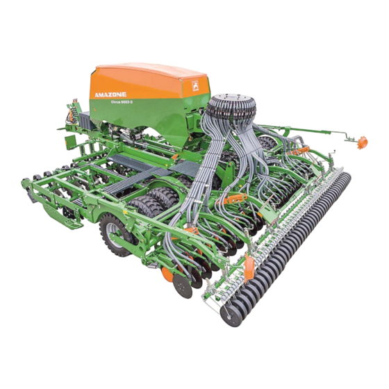
Rigid boom Cirrus 3003 Compact Rigid boom Cirrus 3503 Compact Rigid boom Cirrus 4003 Cirrus 4003-C Folding boom Cirrus 4003-2 Cirrus 4003-2C Folding boom Cirrus 6003-2 Cirrus 6003-2C Cirrus 3003 Compact Fig. 19 Cirrus 4003-C Fig. 20 Cirrus 03 BAH0069-13 12.17... -
Page 48: Main Assemblies Of The Implement
(9) Roller harrow (optional equipment) (4) Distributor head (10) Track marker (5) RoTeC Pro single-disc coulter (11) Tramline marker (6) Crushboard Choice of mounting In front of the disc array In front of the leading roller Cirrus 03 BAH0069-13 12.17... -
Page 49: Overview Of Assembly Groups
(1) with the operating manual the case with a second metering roller in parking position the collection bag the digital scale that is required for calibrating the spread rate. Fig. 24 Cirrus 03 BAH0069-13 12.17... - Page 50 (2) Sealing flap Fig. 26 (1) Metering unit with sluice for implements with two chamber system (2) Flap Fig. 27 (1) Electric motor for the metering roller drive Fig. 28 Cirrus 03 BAH0069-13 12.17...
- Page 51 (2) Handle Fig. 29 Hopper cover for implements with two chamber system Fig. 30 (1) Shutter distributor head (2) Seed tube monitoring Fig. 31 (1) Segment distributor head Fig. 32 Cirrus 03 BAH0069-13 12.17...
- Page 52 Product description RoTeC-Pro single-disc coulter Fig. 33 TwinTeC+ double-disc coulter Fig. 34 Tramline marker Fig. 35 Cirrus 03 BAH0069-13 12.17...
-
Page 53: Safety And Protective Equipment
Product description Safety and protective equipment (1) Blower fan guard Fig. 36 (1) Wheel chocks Fig. 37 (1) The bars serve as a mechanical transport lock for the implement booms Fig. 38 Cirrus 03 BAH0069-13 12.17... -
Page 54: Overview - Supply Lines Between The Tractor And The Implement
The function of the tractor control unit is represented symbolically: Latched, for a permanent oil circulation When the button is pressed, as long as the function is active Float position, free oil flow in the control unit Cirrus 03 BAH0069-13 12.17... - Page 55 Blower fan hydraulic motor (section 6.3, page 137) Important! Always connect this hydraulic line to the tractor. The connection of this hydraulic line to the tractor is required for all of the above-listed hydraulic func- tions. Cirrus 03 BAH0069-13 12.17...
-
Page 56: Transportation Equipment
(2) 2 forwards-facing limiting lights Fig. 41 (1) Transport safety bar (only in combination with the exact following harrow) Fig. 42 (1) 2 x 3 reflectors, yellow, (laterally with a max. spacing of 3 m) Fig. 43 Cirrus 03 BAH0069-13 12.17... -
Page 57: Intended Use
Compliance with all the instructions in this operating manual. Adherence of inspection and maintenance work. Exclusive use of original AMAZONE spare parts. Other uses to those specified above are forbidden and shall be considered as improper. For any damage resulting from improper use ... -
Page 58: Danger Areas And Danger Points
in the area of the swivelling implement sections. when unfolding/folding the implement sections near overhead power lines. in the area of moving parts. underneath raised, unsecured implements or parts of implements. Cirrus 03 BAH0069-13 12.17... -
Page 59: Rating Plate And Ce Mark
(4) Perm. system pressure total weight kg (5) Perm. system pressure Front axle load / drawbar load kg (6) Perm. system pressure rear axle load (7) Perm. system pressure system pressure Fig. 45 (8) Factory (9) Model year (10) Year of manufacture Cirrus 03 BAH0069-13 12.17... -
Page 60: Technical Data
Tyre matrix 400/55 R17.5 T-Pack Number of tyres on [number (integrated) [number T-Pack Number of tyres on U (universal) = Standard equipment = Optional equipment = Special equipment Cirrus 03 BAH0069-13 12.17... - Page 61 T-Pack [number] Number of tyres on S (side) T-Pack Number of tyres on IN (integrated) [number] Number of tyres on T-Pack U (universal) [number] = Standard equipment = Optional equipment = Special equipment Cirrus 03 BAH0069-13 12.17...
-
Page 62: Road Transport Data
2500 2500 2500 3000 3000 (see rating plate and section 6.1.1.1, page 132) Max. permitted speed see section 9, page 213 In transport position, the filling auger does not change the total height of the implement Cirrus 03 BAH0069-13 12.17... -
Page 63: Necessary Tractor Equipment
The workplace-related emission value (acoustic pressure level) is 70 dB(A), measured in operating condition at the ear of the tractor driver with the cab closed. Measuring unit: OPTAC SLM 5. The noise level is primarily dependent on the vehicle used. Cirrus 03 BAH0069-13 12.17... -
Page 64: Layout And Function
The implement is equipped with a main frame with integrated running gear for turning at the end of the field or for transporting on the roads. Implements with pivoting booms can be folded to a width of 3 m for transporting. Cirrus 03 BAH0069-13 12.17... -
Page 65: Control Terminal For Implements With Isobus System
The implement can be connected to any ISOBUS-compatible control terminal. If the tractor has an ISOBUS system, the AMAZONE job computer can also be connected to the existing ISOBUS socket of the tractor and operated with the on-board terminal. As an option, the combination can be delivered e.g. -
Page 66: Service Brake System
For implements without a brake system, it may be necessary to retrofit the brake system. Observe the national regulations. You can obtain information on this from your local implement dealer/importer. Cirrus 03 BAH0069-13 12.17... -
Page 67: Parking Brake
The braking force compensator serves to manually adjust the deceleration of the imple- ment for the respective load using the brake load adjustment lever (Fig. 51/1). Fig. 51 Cirrus 03 BAH0069-13 12.17... -
Page 68: Hydraulic Service Brake System
Before taking into operation, check the officially approved registration of your implement without service brake system. Subsequently installed accessories change the axle load and may make it necessary to equip the implement with a service brake system. Cirrus 03 BAH0069-13 12.17... -
Page 69: Accessories Kit With The Operating Manual
(Fig. 53). Other sources are also possible (refer to the control terminal operating manual). The working speed data is used to determine: the worked area (hectare counter) the required speed for the speed of the metering roller(s) Fig. 53 Cirrus 03 BAH0069-13 12.17... -
Page 70: Controlling The Implement With The Control Terminal
(not in combination with the T-Pack S) Crushboard, optional At the front in front of the disc array (not in combination with the T-Pack S) At the rear in front of the roller tyres Disc array. Cirrus 03 BAH0069-13 12.17... -
Page 71: T-Pack S
The T-Pack IN is permanently integrated in the implement. A second option for performing work in the area between tractor tyres is the T Pack U (see below) mounted on the tractor's three-point hitch. Fig. 56 Cirrus 03 BAH0069-13 12.17... -
Page 72: T-Pack U
(Fig. 58). Mounting at the front requires additional mounting parts. The procedures for mounting on the tractor and for operation can be found in the T Pack U operating manual. Fig. 58 Cirrus 03 BAH0069-13 12.17... -
Page 73: Crushboard
(Fig. 61/1). When the tractor control unit is actuated, the hydraulic cylinder rests against the stops. The maximum working intensity is achieved if no stop (Fig. 61/1) is resting against it. Fig. 61 Cirrus 03 BAH0069-13 12.17... -
Page 74: Tractor Wheel Mark Eradicator
This protects the individual discs against damage. Fig. 63 The pointer (Fig. 64/1) marks the working depth of the disc array on the scale (Fig. 64/2). The scale is used as a reference value. Fig. 64 Cirrus 03 BAH0069-13 12.17... - Page 75 TwinTeC coulter is adjusted. both side plates in a vertical direction. When delivered, the outer discs are screwed in the basic position. The marking (Fig. 66/1) indicates the basic position. Fig. 66 Cirrus 03 BAH0069-13 12.17...
-
Page 76: Roller
The tyres of the roller can be selectively supplied with Matrix tyres or tyres with AS tread. The distance between the tyres and the adjusta- ble scraper (Fig. 67/1) should not be less than 15 Fig. 67 Cirrus 03 BAH0069-13 12.17... - Page 77 16.6 cm, three coulters. Fig. 68 Tyres with AS tread (optional equipment) With their transverse tread, AS tyres have a high self-propulsion and ensure for an equal reconsol- idation over the entire working width. Fig. 69 Cirrus 03 BAH0069-13 12.17...
-
Page 78: Furrow Ridge Leveller
Implements with TwinTeC+ double-disc coulters have swivelling furrow ridge levellers. With a crank (Fig. 72/1) at the middle of the implement and 2 levers on the swivelling booms, the furrow ridge levellers can be adjusted as required. Fig. 72 Cirrus 03 BAH0069-13 12.17... -
Page 79: Hopper
The hopper covers (Fig. 74/1) seal the hopper pressure-tight. Fig. 74 The sieve meshes serve to collect foreign ob- jects and as a rack when filling the chambers with material in sacks. Fig. 75 Cirrus 03 BAH0069-13 12.17... -
Page 80: Filling Auger
In terms of operation, a distinc- tion is made between rigid and folding imple- ments. The filling auger for a folding implement is shown. Fig. 77 Cirrus 03 BAH0069-13 12.17... -
Page 81: Fill Level Monitoring
Fit the sensor to the higher bracket. Fine seed types (e.g. rapeseed): Fit the sensor to the lower bracket (factory setting). Fertiliser: Fit the sensor to one of the two brackets, depending on the spread rate. Cirrus 03 BAH0069-13 12.17... -
Page 82: Metering
The higher the speed of the electric motor, the greater the spread rate. automatically adjusts to changing working speeds. can be increased during operation when changing from from normal to heavy soils by pressing a button on the control terminal. Cirrus 03 BAH0069-13 12.17... - Page 83 (Fig. 81/1) of the metering roller can be enlarged by repositioning the wheels and the plates. Fig. 81 The volume of some metering rollers can be modified by repositioning/removing the existing wheels and inserting metering wheels without chambers. Fig. 82 Cirrus 03 BAH0069-13 12.17...
-
Page 84: Metering Roller Diagram Table
Layout and function 5.9.1 Metering roller diagram table Metering roller Volume: ....7.5 cm Metering roller Volume: ....20 cm Metering roller Volume: ....40 cm Cirrus 03 BAH0069-13 12.17... - Page 85 Layout and function Metering roller Volume: ....120 cm Metering roller Volume: ....210 cm Cirrus 03 BAH0069-13 12.17...
- Page 86 Layout and function Metering roller Volume: ....350 cm Metering roller Volume: ....600 cm Cirrus 03 BAH0069-13 12.17...
- Page 87 Layout and function Metering roller Volume: ....660 cm Metering roller Volume: ....880 cm Cirrus 03 BAH0069-13 12.17...
-
Page 88: Table - Metering Rollers, Seed
120 cm³ 210 cm³ Seed Beans Buckwheat Dinkel Peas Flax (dressed) Barley Grass seed Oats Millet Caraway Lupins Alfalfa Maize Poppy Oilseed (moist dressing) Fodder radish Phacelia Rapeseed Red clover Mustard Sunflowers Turnips Triticale Wheat Vetches Cirrus 03 BAH0069-13 12.17... -
Page 89: Table - Metering Rollers, Fertiliser
Caraway Lupins Alfalfa Maize Poppy Oilseed flax (moist dressing) Fodder radish Phacelia Rapeseed Red clover Mustard Sunflowers Turnips Triticale Wheat Vetches 5.9.2.1 Table – metering rollers, fertiliser Metering rollers 350 cm³ 660 cm³ Fertiliser Fertiliser (granular) Cirrus 03 BAH0069-13 12.17... -
Page 90: Metering - One Chamber System
1 is connected to the front chamber. Fig. 84 When calibrating the spread rate, the metered material falls into the collection bag through an opening (Fig. 85/1). The calibration procedure is performed consecutively on both metering units. Fig. 85 Cirrus 03 BAH0069-13 12.17... - Page 91 The rear metering roller is switched off and the front metering roller is started automatically as soon as the seed level reaches the low level sensor in the rear chamber. Cirrus 03 BAH0069-13 12.17...
-
Page 92: Calibrating The Spread Rate
The calibration start button must be kept pressed during the entire calibration proce- dure. The metering roller stops automatical- ly as soon as the calibration procedure has ended. For a more detailed description, refer to the "ISOBUS software" operating manual. Fig. 88 Cirrus 03 BAH0069-13 12.17... - Page 93 A digital scale is include in the scope of delivery. Fig. 89 The icon (Fig. 90/1) marks the holder for the digital scale. The holder is used to hang the digital scale during the calibration procedure. Fig. 90 Cirrus 03 BAH0069-13 12.17...
- Page 94 The order of the numbered metering units can be selected. During the calibration procedure Fig. 92 the locking plate of the right sluice stays closed. the seed quantity is not halved. Cirrus 03 BAH0069-13 12.17...
-
Page 95: Automatic Seed Rate Increase
(Fig. 94/1) the shutter distributor head with the plugs (Fig. 94/3). The assembly tool (Fig. 94/2) is used to insert the plugs in the segment distributor head. Fig. 94 Cirrus 03 BAH0069-13 12.17... -
Page 96: Seed Pre-Metering
Example Values that can be set on the control terminal Probable working speed: ......10 km/h Starting speed: ......50 % Time to achieve working speed: .. 8 seconds Fig. 95 Cirrus 03 BAH0069-13 12.17... -
Page 97: Blower Fan
(see section 5.10.3). the tractor PTO shaft (see section 5.10.4). Fan suction guard screen The fan suction guard screen prevents the suc- tion of straw residues into the fan under very dry conditions. Fig. 97 Cirrus 03 BAH0069-13 12.17... - Page 98 The pressure gauges (Fig. 99) show the pressure in chambers 1 and 2. The pressure difference must not be greater than 5 mbar. Fig. 99 Cirrus 03 BAH0069-13 12.17...
-
Page 99: One Chamber System Blower Fan Speed
(Fig. 100/2), e.g. rapeseed or grass seed Grains or legumes (Fig. 100/3) and the application rate (Fig. 100/4). Example: Cirrus 3003 Compact Grain application rate: 130 kg/ha (Fig. 100/4) Required blower fan speed: 3,200 rpm. Cirrus 03 BAH0069-13 12.17... -
Page 100: Two Chamber System Blower Fan Speed
(Fig. 101/5) and the application rate (Fig. 101/6). Example: Cirrus 6003-2 Fertiliser application rate: 150 kg/ha (Fig. 101/3) Grain application rate: 130 kg/ha (Fig. 101/6) Required blower fan speed: 3600 rpm. Cirrus 03 BAH0069-13 12.17... -
Page 101: Connecting The Blower Fan To The Tractor Hydraulics
Set the blower fan speed at the flow control valve of the tractor (see section 8.9.1). at the pressure relief valve of the hydraulic motor (see section 8.9.2), if the tractor has no flow control valve. Fig. 103 Cirrus 03 BAH0069-13 12.17... -
Page 102: Blower Fan Connection To The Tractor Pto Shaft (On-Board Hydraulic System)
The hydraulic motor (Fig. 105/1) is fastened on the rear wall of the blower fan. Fig. 105 In a closed circuit, the implement carries the hy- draulic fluid in an oil tank (Fig. 106/1). Fig. 106 Cirrus 03 BAH0069-13 12.17... -
Page 103: Distributor Head
the tramline coulters do not deposit any seeds on the ground. The shutters are actuated by a computer- controlled electric motor (Fig. 108/2). Fig. 108 Cirrus 03 BAH0069-13 12.17... -
Page 104: Segment Distributor Head
(Fig. 111/1) that detects the seed flow. A warning message is issued when the seed flow in a monitored seed line hose is interrupted or large deviations occur in the flow rate between the monitored seed line hoses. Fig. 111 Cirrus 03 BAH0069-13 12.17... -
Page 105: Rotec-Pro Control Coulter (Optional Equipment)
Fig. 113 The seed placement depth depends on the factors Soil type (light to heavy) Forward speed Position of the shallow seeding disc/cleaning disc coulter pressure Cirrus 03 BAH0069-13 12.17... - Page 106 The pressure gauge (Fig. 115/1) shows the tractor driver if working is being carried out with increased coulter pressure. The coulters work with increased coulter pressure if the pressure gauge (Fig. 115/1) indicates pressure. Fig. 115 Cirrus 03 BAH0069-13 12.17...
-
Page 107: Twintec+ Double-Disc Coulter (Optional Equipment)
The seed placement depth depends on the set placement depth of the seed the soil conditions the forward speed. The seed placement depth is adjusted with the seed placement depth range the seed placement depth. Cirrus 03 BAH0069-13 12.17... - Page 108 (Fig. 118/1) is inserted in the rear hole (factory setting). Fig. 118 For placement depths between approx. 4 and 10 cm, the rear fitting bolt (Fig. 119/1) is inserted in the front hole. Fig. 119 Cirrus 03 BAH0069-13 12.17...
-
Page 109: Coulter Pressure, Hydraulically Adjustable
The pressure gauge (Fig. 121/2) indicates the Fig. 121 current coulter pressure. The coulter pressure is infinitely variably adjusted using the pressure control valve (Fig. 121/1) and can only be built up and changed when the blower fan is running. Cirrus 03 BAH0069-13 12.17... -
Page 110: Exact Following Harrow (Optional Equipment)
Exact following harrow tine position Distance "A" 230 to 280 mm When correctly set, the harrow tines of the exact following harrow should: lie horizontally on the ground and have 5-8 cm clearance underneath. Fig. 124 Cirrus 03 BAH0069-13 12.17... -
Page 111: Exact Following Harrow Pressure Adjustment
If pressure is applied to the control unit, the exact following harrow pressure increases and the lever rests against the top pin. If the coulter pressure is reduced, the lever rests against the bottom pin. Fig. 125 Cirrus 03 BAH0069-13 12.17... -
Page 112: Roller Harrow (Optional Equipment)
Adjustments can be made to the pitch of the harrow tines the working depth of the harrow tines. Fig. 127 The crank (Fig. 128/1) is used to adjust the roll- er contact pressure. Fig. 128 Cirrus 03 BAH0069-13 12.17... -
Page 113: Track Marker
After passing the obstacle, the tractor driver unfolds the track marker again by actuating the control unit. Cirrus 03 BAH0069-13 12.17... -
Page 114: Tramlines
the tramline-inactive seed lines, which are connected to the passive shutters on the shutter dis- tributor head. If not ordered otherwise, the track width of the tramline is set to 1.80 m. Cirrus 03 BAH0069-13 12.17... - Page 115 The track width (a) of the tramline corresponds to that of the cultivating tractor and is adjustable. The wheelmark width (c) of the tramline increases with an increasing number of tramline coulters fitted next to each other. Cirrus 03 BAH0069-13 12.17...
-
Page 116: Examples For Creating Tramlines
3. On the same line in column "D" under the inscription "START", take the reading of the tramline counter for the first field run (tramline counter 2) and enter it on the on-board computer . Input this value directly before commencing the first field run. Cirrus 03 BAH0069-13 12.17... - Page 117 Layout and function Fig. 134 Cirrus 03 BAH0069-13 12.17...
-
Page 118: Tramline Rhythm 4, 6 And 8
(see Fig. 135). In this case, the cultivating implement works with half the working width during the first field pass. After the first field run, restore the full implement working width. Cirrus 03 BAH0069-13 12.17... -
Page 119: Tramline Rhythms 2 And 21
The seed feed to the tramline coulters may be interrupted by the implement with tramline rhythm 2 plus, only the right side of the implement. tramline rhythm 21 only on the left side of the implement. Work always starts on the right hand edge of the field. Cirrus 03 BAH0069-13 12.17... -
Page 120: One-Sided Switching
with one distributor head, by closing the required outputs in the distributor head. with two distributor heads (Fig. 138/1), by interrupting the seed supply to one distributor head (see section 5.18.4.3). Fig. 138 Cirrus 03 BAH0069-13 12.17... -
Page 121: One-Sided Switching For Implements With A Shutter Distributor Head
Implements with segment distributor head The installation of an insert (Fig. 140/1) in the distributor head closes the outlets to the coulters of one implement half. Halve the spread rate when working with half the working width. Fig. 140 Cirrus 03 BAH0069-13 12.17... - Page 122 Fig. 141 The partition walls (Fig. 142/1) can be individually controlled using the control terminal of the job computer. The partition walls are actuated by two computer-controlled electric motors (Fig. 142/2). Fig. 142 Cirrus 03 BAH0069-13 12.17...
-
Page 123: One-Sided Switching For Implements With 2 Distributor Heads
one metering unit (Fig. 144/1) supplies both distribution heads with seed or fertiliser at the same time. Fig. 144 the lever (Fig. 145/1) is in the middle position under the metering unit. Fig. 145 Cirrus 03 BAH0069-13 12.17... - Page 124 requires the halving of the application rate. Fig. 147 Optionally, a setting motor (Fig. 148/1) actuates the electronic one-sided switching. If the one-sided switching is actuated electrically, the application rate is set automatically. Fig. 148 Cirrus 03 BAH0069-13 12.17...
- Page 125 Lever position, right side (viewed from the direct of travel): the supply of the right implement half is stopped. Fig. 149 Lever position, left side (viewed from the direct of travel): the supply of the left implement half is stopped. Fig. 150 Cirrus 03 BAH0069-13 12.17...
-
Page 126: Double Tramline Switching
Display, tramline counter left side: ............1 / 2 / 0 / 4 / 5 / 6 / 7 / 8 / 9 / 10 Display, tramline counter right side: ............1 / 2 / 3 / 4 / 5 / 6 / 0 / 8 / 9 / 10 Cirrus 03 BAH0069-13 12.17... -
Page 127: Tramline Marker
The monitor is characterised by the clear, glare- free representation of multiple camera images simultaneously. The camera system can be quickly mounted and dismounted with simple plug connections. Fig. 154 Cirrus 03 BAH0069-13 12.17... -
Page 128: Greendrill
155/2) is conveyed and distributed equally by baffle plates (Fig. 155/3). The GreenDrill control terminal has a selection menu for assisting with the calibration procedure. The seeding is interrupted automatically when turning at the end of the field. Cirrus 03 BAH0069-13 12.17... -
Page 129: Initial Commissioning
This does not apply to equipment movements that: are continuous or are automatically locked or require a float position or pressure position due to their function. Cirrus 03 BAH0069-13 12.17... -
Page 130: Checking The Suitability Of The Tractor
The front axle of the tractor must always be loaded with at least 20 % of the empty weight of the tractor. The tractor must achieve the brake delay specified by the tractor manufacturer, even with a mounted or trailed implement. Cirrus 03 BAH0069-13 12.17... -
Page 131: Calculating The Actual Values For The Total Tractor Weight, Tractor Axle Loads And Tyre Load-Bearing Capacity, As Well As The Required Minimum Ballast Weight
§ 70 of the German Regulations Authorising the Use of Vehicles for Road Traffic and the required approval according to § 29, paragraph 3 of the German Road Traffic Regulations. Cirrus 03 BAH0069-13 12.17... -
Page 132: Data Required For The Calculation (Hitched Implement)
[m] Tractor wheel base See tractor operating manual or vehicle documents or measurement [m] Distance between the centre of the rear See tractor operating manual or vehicle axle and the centre of the lower link documents or measurement connection Cirrus 03 BAH0069-13 12.17... -
Page 133: Of The Tractor For Assurance Of The Steering Capability
(section 6.1.1.7). 6.1.1.6 Tractor tyre load capacity Enter the double value (two tyres) of the approved load capacity (see, for example, tyre manufacturer's documentation) in the table (section 6.1.1.7). Cirrus 03 BAH0069-13 12.17... -
Page 134: Table
(if required) attached to the tractor for the minimum front ballast (G V min You must use a front weight, which is equal to at least the required minimum front ballast (G V min Cirrus 03 BAH0069-13 12.17... -
Page 135: Requirements For Tractor Operation With Trailed Implements
that the permissible total weight of the tractor is complied with. that the approved load capacities of the tractor tyres are not exceeded. Cirrus 03 BAH0069-13 12.17... -
Page 136: Securing The Tractor/Implement Against Unintentional Start-Up And Rolling
This is how to prevent unintentional falling: 3. Switch off the tractor PTO shaft. 4. Shut down the tractor engine. 5. Remove the ignition key. 6. Apply the tractor parking brake. 7. Secure the implement with wheel chocks against unintentionally rolling away. Cirrus 03 BAH0069-13 12.17... -
Page 137: Installation Regulations For The Hydraulic Fan Drive Connection
The capacity of the tractor's oil tank (Fig. 157/4) should be at least twice the oil flow rate. If the hydraulic fluid heats up excessively, the installation of an oil cooler is required at a specialist workshop. Cirrus 03 BAH0069-13 12.17... -
Page 138: Coupling And Uncoupling The Implement
Actuate the operating controls for the tractor's 3-point hydraulic sys- from the workplace provided. if you are outside of the danger area between the tractor and the implement. Cirrus 03 BAH0069-13 12.17... - Page 139 Risk of contusions, catching, and knocks when the implement unexpectedly releases from the tractor! Check the tensioned crosspiece and the drawbar for visible defects whenever the implement is coupled. Have any visible defects fixed without delay in a specialist workshop. Cirrus 03 BAH0069-13 12.17...
-
Page 140: Dual-Circuit Pneumatic Service Brake System
(red) is connected. Only then can the wheel chocks be removed. Compliance with the maintenance intervals is essential for the correct function of the brake system. Cirrus 03 BAH0069-13 12.17... - Page 141 (red) is connected. The brake is not released if the implement's parking brake is applied. To make sure that the implement is braked after uncoupling, apply the implement's parking brake be- forehand. Only release the parking brake once the implement has been coupled up to the tractor. Cirrus 03 BAH0069-13 12.17...
-
Page 142: Coupling The Brake And Supply Lines
The operating brake of the implement moves out of the brake position immediately the red couling head has been coupled. DANGER Check the routing of the brake line. The brake line must not chafe on foreign parts. Cirrus 03 BAH0069-13 12.17... - Page 143 159/2) on the tractor, in accordance with regulations. 8. Fasten the couling head of the supply line (red) in the coupling marked red on the tractor, in accordance with regulations. Fig. 159 9. Remove wheel chocks. 10. Release the implement parking brake. Cirrus 03 BAH0069-13 12.17...
-
Page 144: Uncoupling The Supply And Brake Line
1. Secure the implement with wheel chocks (Fig. 160). Fig. 160 2. Apply the implement's parking brake. Fig. 161 Cirrus 03 BAH0069-13 12.17... -
Page 145: Control Element For The Dual Circuit Pneumatic Brake System
Fig. 163 With a full compressed air tank, the brakes are released immediately when the supply line (red) is connected to the tractor. The button (Fig. 163/1) can then no longer be moved. Cirrus 03 BAH0069-13 12.17... -
Page 146: Position Of The Brake Load Adjustment Lever For The Dual-Circuit Pneumatic Service Braking System
Example: Position of the brake load adjustment lever (Fig. 164/1) for implements with full hopper. Fig. 164 Example: Position of the brake load adjustment lever (Fig. 165/1) for implements with empty hopper. Fig. 165 Cirrus 03 BAH0069-13 12.17... -
Page 147: Hydraulic Service Brake System
10 seconds with the engine running. This fills the hydro accumulator. When the hydro accumulator is full, the implement's service brake system responds when the tractor brake pedal or the tractor parking brake is applied. Cirrus 03 BAH0069-13 12.17... - Page 148 Fig. 168 8. Apply the tractor parking brake, switch off the tractor engine, and remove the ignition key. 9. Remove wheel chocks. 10. Release the implement parking brake. Cirrus 03 BAH0069-13 12.17...
-
Page 149: Uncoupling The Hydraulic Service Brake System
Before uncoupling the implement from the tractor, secure it with 2 wheel chocks and apply the implements parking brake. 1. Secure the implement with wheel chocks (Fig. 169). Fig. 169 2. Apply the implement's parking brake. Fig. 170 Cirrus 03 BAH0069-13 12.17... - Page 150 5. Push the hydraulic socket onto the protective cap (Fig. 172/1). The protective cap is secured to the hose cabinet and protects the socket against soiling in the parking position. Fig. 172 Cirrus 03 BAH0069-13 12.17...
-
Page 151: Hydraulic Hose Lines
Push the hydraulic plug(s) into the hydraulic socket(s) until the hy- draulic plug(s) perceivably lock(s). Check the coupling points of the hydraulic hose lines for proper fit and sealing. Cirrus 03 BAH0069-13 12.17... -
Page 152: Uncoupling The Hydraulic Hose Lines
(markings of the hydraulic lines, see section 4.4). Fig. 173 7.3.2 Uncoupling the hydraulic hose lines 1. Put the tractor control units into the float position. 2. Disconnect the hydraulic plug and store in the hose cabinet. Fig. 174 Cirrus 03 BAH0069-13 12.17... -
Page 153: Coupling The Implement To The Tractor
Use the intended equipment to connect the tractor and the implement in the proper way. When coupling the implement to the tractor's three-point hydraulic system, ensure that the attachment categories of the tractor and the implement are the same. Cirrus 03 BAH0069-13 12.17... - Page 154 When the implement is uncoupled and the running gear is extended (implement raised) the pressure in the supply line can increase so much that later coupling to the tractor becomes impossible. Cirrus 03 BAH0069-13 12.17...
-
Page 155: Coupling The T-Pack U
The implement is equipped with a telescopic drawbar tube (Fig. 175/1). The distance between the lower link and the implement frame can be adjusted (see section 12.3.1). Fig. 175 Cirrus 03 BAH0069-13 12.17... - Page 156 510 mm 1310 mm Cirrus 3503 Compact 510 mm 1310 mm Cirrus 4003 (rigid) 700 mm 1710 mm 510 mm 1110 mm Cirrus 4003-2 with 910 mm 1110 mm Cirrus 6003-2 T-Pack In 365 mm 620 mm Cirrus 03 BAH0069-13 12.17...
- Page 157 Design of the ball sleeve with catch shell (see the tractor operating manual). 4. Secure each ball sleeve with a lynch pin. CAUTION Danger of getting crushed in the ar- ea of the moving tensioned cross- Fig. 180 piece. Cirrus 03 BAH0069-13 12.17...
- Page 158 13. Raise the tractor's lower link until the stand comes free of the ground. 14. Remove the bolt (Fig. 181/1). Fig. 181 15. Fold up the stand, locate it with the pin (Fig. 182/1) and secure with the lynch pin. Fig. 182 Cirrus 03 BAH0069-13 12.17...
- Page 159 16. Push the wheel chocks into the holders and secure. Fig. 184 17. Release the parking brake of the implement. 18. Before moving off: Check the function of the braking and lighting system Perform a brake test. Fig. 185 Cirrus 03 BAH0069-13 12.17...
-
Page 160: Uncoupling The Implement
2. Align the tractor and implement straight and park the empty implement on a level parking surface on solid ground. 3. Fold or unfold the booms on the implement. 4. Lower the implement via the integrated running gear. Cirrus 03 BAH0069-13 12.17... - Page 161 Do not put the jack into support position if the combination is equipped with the T-Pack IN (Fig. 187/1). The implement is supported by the T-Pack IN after it is uncoupled from the tractor. Fig. 187 Cirrus 03 BAH0069-13 12.17...
- Page 162 11. Uncouple the supply lines, starting with the service brake system Dual-circuit pneumatic service braking system: see section Uncoupling the supply and brake line, page Hydraulic service brake system: see section Uncoupling the hydraulic service brake system, 149. page Cirrus 03 BAH0069-13 12.17...
- Page 163 (see tractor operating manual). 14. Uncouple the tractor's lower link. 15. Pull the tractor forwards. DANGER While pulling the tractor forwards no personnel are allowed to be between the tractor and the implement! Fig. 191 Cirrus 03 BAH0069-13 12.17...
-
Page 164: Connect/Disconnect The Pto Shaft Driven Hydraulic Pump
PTO shaft. The hydraulic pump is equipped with a QC fastener. Make sure that the QC fastener has engaged correctly. 6. Set the adjustment segments (Fig. 192/2) so that the buffers rest against them. Fig. 192 Cirrus 03 BAH0069-13 12.17... -
Page 165: Uncoupling The Hydraulic Pump
2. Switch off the tractor PTO shaft, apply the tractor parking brake, switch off the tractor engine, and remove the ignition key. Wait until the PTO shaft stops moving. 3. Remove the hydraulic pump (Fig. 193/1) from the tractor's PTO shaft and insert it in the mount. Fig. 193 Cirrus 03 BAH0069-13 12.17... -
Page 166: Settings
Remove the ignition key. CAUTION Switch off control terminal before road transport. before adjustment, maintenance and repair work. Risk of accident due to unintended movements of the metering unit or other implement components caused by radar pulses. Cirrus 03 BAH0069-13 12.17... -
Page 167: Swivel The Holding Pipe For The Lighting
Make the same adjustments on all segments. Fig. 195 5. Direct people out of the danger area. 6. Actuate the tractor control unit (blue): lower running direction. 6.1 The piston of the hydraulic cylinder retracts to the stop. Cirrus 03 BAH0069-13 12.17... -
Page 168: Disc Array
2. Adjust the disc in such a manner that the soil processed is not transported to the inside or outside, but is equally placed behind the discs. 3. Tighten the screws (Fig. 196/1) firmly. Fig. 196 Cirrus 03 BAH0069-13 12.17... - Page 169 1. Remove the hexagon bolt (Fig. 198/1). 2. Pull the side panel (Fig. 198/2) off of the spigot (Fig. 198/3) and reinsert on the spigot at the desired height. 3. Screw on the side panel with three hexagon bolts. Fig. 198 Cirrus 03 BAH0069-13 12.17...
-
Page 170: Moving The Wheel Mark Eradicator Into Working Position (On The Field)
Moving the wheel mark eradicator into transport position To transport the implement, raise it high enough so that the wheel mark eradicators cannot be damaged. Fig. 200 Cirrus 03 BAH0069-13 12.17... -
Page 171: Repositioning The Low Level Sensor
The metering roller can be replaced more easily if the hopper is empty. 1. Close the opening between the hopper and the metering unit (only necessary when the hopper is full). 1.1 Remove the key (Fig. 202/1) from the holder. Fig. 202 Cirrus 03 BAH0069-13 12.17... - Page 172 (Fig. 204/4) (see section 8.8, page 174). Fig. 204 2. Undo, but do not remove, the two screws (Fig. 205/1). Fig. 205 3. Turn the bearing cover and pull it off. Fig. 206 Cirrus 03 BAH0069-13 12.17...
- Page 173 O-ring (Fig. 207/1). Replace the O-ring if it is damaged. Fig. 207 4. Remove the metering roller. Install the metering roller in the reverse sequence. Fig. 208 Secure the shutter in the parking position. Close the flap. Fig. 209 Cirrus 03 BAH0069-13 12.17...
-
Page 174: Calibrating The Spread Rate
8.8.1, page 175 Cirrus 6003-2 with 2 distributor heads see section 8.8.2, page 176 Cirrus 4003-C see section 8.8.3, page 178 Cirrus 4003-2C see section 8.8.3, page 178 Cirrus 6003-2C see section 8.8.3, page 178 Cirrus 03 BAH0069-13 12.17... -
Page 175: Calibrating The Spread Rate Cirrus 3003 Compact / Cirrus 3503 Compact / Cirrus 4003 / Cirrus 4003-2 Cirrus 6003-2 With 1 Distributor Head
Always engage the lever (Fig. 211/1). Fig. 211 All implement types: 6. Repeat the calibration procedure according to the control terminal operating manual until the desired spread rate is achieved. 7. Empty the collection bag. 8. Close the injector sluice. Cirrus 03 BAH0069-13 12.17... -
Page 176: Calibrating The Spread Rate Cirrus 6003-2 With 2 Distributor Heads
Fig. 212 5. Open the sealing flap (Fig. 213/1) of the left injector. The sealing flap of the right injector stays closed. The handle (Fig. 213/2) is used for operating the sealing flap. Fig. 213 Cirrus 03 BAH0069-13 12.17... - Page 177 8. Repeat the calibration procedure according to the software operating manual until the desired spread rate is achieved. 9. Remove the collection bag. 10. Close the sealing flap under the metering unit. 11. Engage the lever (Fig. 216/1) of the mechanical one-sided switching in the middle position. Fig. 216 Cirrus 03 BAH0069-13 12.17...
-
Page 178: Calibrating The Spread Rate Cirrus 4003-C / Cirrus 4003-2C / Cirrus 6003-2C
The flap for the right sluice stays closed. 2.1 Release the tensioning hook (Fig. 217/1) to open the flap (Fig. 217/2). Fig. 217 3. Push the collecting bag (Fig. 218/1) to the stop under the metering unit. Fig. 218 Cirrus 03 BAH0069-13 12.17... - Page 179 7. Repeat the calibration procedure until the desired spread rate is achieved. 8. Empty the collection bag. 9. Close the flap under the metering unit. 10. Engage the lever (Fig. 221/1) of the mechanical one-sided switching in the middle position. Fig. 221 Cirrus 03 BAH0069-13 12.17...
-
Page 180: Setting The Blower Fan Speed
The pressure relief valve of the blower fan can be installed in two versions with round outer contour (Fig. 222/1), with hexagonal outer contour (Fig. 223/1). The setting of the blower fan speed depends on the version of the pressure relief valve. Cirrus 03 BAH0069-13 12.17... -
Page 181: Setting The Blower Fan Speed Via The Flow Control Valve Of The Tractor
3. Set the blower fan speed during operation by adjusting the tractor PTO shaft speed. Do not exceed the following speeds: max. 1000 rpm PTO shaft speed, max. 4000 rpm blower fan speed. The control terminal displays the blower fan speed. Fig. 224 Cirrus 03 BAH0069-13 12.17... -
Page 182: Pressure Relief Valve With Round Outer Contour
Do Do not exceed the maximum blower fan speed of 4000 rpm. Blower fan speed Turning to the right: increases the nominal blower fan speed Turning to the left: reduces the nominal blower fan speed. 3. Tighten the lock nut. Cirrus 03 BAH0069-13 12.17... -
Page 183: Pressure Relief Valve With Hexagonal Outer Contour
Set the nominal blower fan speed on the on-board computer. If the actual speed deviates by more than 10 % from the target speed, an acoustic signal is issued along with a screen display. It is possible to set the percentage deviation. Cirrus 03 BAH0069-13 12.17... -
Page 184: Pressure Monitoring In The Two Chamber Hopper
1 (front) and 2 (rear). The pressure difference must not be greater than 5 mbar. If the required air pressure is not reached, check the system for leaks. Amongst other things, check if the hopper cover is closed. Fig. 229 Cirrus 03 BAH0069-13 12.17... -
Page 185: Rotec-Pro Control Coulter - Adjusting The Placement Depth
Positioning the depth limiting discs Each depth limiting disc can be engaged in 4 positions on the coulter, or be removed from the coulter (see Fig. 230). Position Placement Shallow Seeding without depth limiting Deep disc Fig. 230 Cirrus 03 BAH0069-13 12.17... - Page 186 A light knock on the centre of the disc helps to latch it into position. Attachment of the depth limiting disc with the marking "K" on the short coulter the marking "L" on the long coulter. Cirrus 03 BAH0069-13 12.17...
-
Page 187: Setting The Coulter Pressure
(Fig. 234/2) of the extended piston rod. 4. Tighten up the wing nut. 5. Depressurize the tractor control unit (blue). Fig. 234 6. Set the desired increased rate on the control terminal (see control terminal operating manual). Cirrus 03 BAH0069-13 12.17... -
Page 188: Twintec+ Double-Disc Coulter - Adjusting The Placement Depth
2. Loosen both fitting bolts (Fig. 235/1). 3. Lift the wheel carriers (Fig. 235/2) by hand and reposition the rear fitting bolt. 4. Screw on the two fitting bolts (Fig. 235/1) (126 Nm). Fig. 235 Cirrus 03 BAH0069-13 12.17... -
Page 189: Adjusting The Seed Placement Depth
Fig. 236 1. Release the rotation lock for the crank and engage the clamp in the notch (Fig. 237/1). Fig. 237 2. Use the crank (Fig. 238/1) to adjust to the seed placement depth. Fig. 238 Cirrus 03 BAH0069-13 12.17... - Page 190 (Fig. 241/1) relative to each other and adjust with the top link (Fig. 241/2) if the position has changed. 5. Tighten the lock nuts to secure the length adjustment of the top link. Fig. 241 Cirrus 03 BAH0069-13 12.17...
-
Page 191: Setting The Coulter Pressure
4. The coulter pressure is infinitely variably adjusted using the pressure control valve (Fig. 242/1). The pressure gauge (Fig. 242/2) indicates the current coulter pressure. Fig. 242 The maximum coulter pressure is reached at approx. 95 bar. Cirrus 03 BAH0069-13 12.17... -
Page 192: Adjusting The Harrow Tines - Twintec+ Double-Disc Coulter
1. Raise the coulters until the harrow tines are directly above the ground, but not touching 2. Insert the pin (Fig. 245/1) and secure with a linch pin. The pin serves as a stop for the harrow tines (Fig. 245/2). Fig. 245 Cirrus 03 BAH0069-13 12.17... -
Page 193: Adjusting The Working Depth Of The Harrow Tines
2. Unscrew the hex. bolt (Fig. 248/2). 3. Swivel the harrow tines (Fig. 248/1) into parking position. 4. Insert the pin (Fig. 248/3) and secure with a linch pin (Fig. 248/4). 5. Tighten the hex. bolt (Fig. 248/2). Fig. 248 Cirrus 03 BAH0069-13 12.17... -
Page 194: Adjusting The Furrow Ridge Levellers
4. Secure the setting. Fig. 251 4.1 Slowly release the spring-loaded lever (Fig. 251/3). 5. Check the work performed by the furrow ridge levellers (Fig. 251/1) after each placement depth adjustment. Cirrus 03 BAH0069-13 12.17... -
Page 195: Exact Following Harrow
Fig. 252 Transport position Before transporting, push the square tube (Fig. 252/1) with outer harrow into the harrow carrier pipe to the stop and secure in place with the screws. Cirrus 03 BAH0069-13 12.17... -
Page 196: Exact Following Harrow Tine Position
1.1 Extend and retract the piston rod of the hydraulic cylinder for the exact following harrow pressure adjustment consecutively. 1.1 Insert one pin respectively (Fig. 254/1) below and above the stop (Fig. 254/2) into the adjusting segment and secure with linch pins. Fig. 254 Cirrus 03 BAH0069-13 12.17... -
Page 197: Roller Harrow
Roller contact Roller diameter pressure D [mm] F [kg] 330 mm max. 35 kg The roller contact pressure "F" must not exceed the table value. Higher pressures than indicated may damage the roller harrow. Fig. 257 Cirrus 03 BAH0069-13 12.17... -
Page 198: Adjusting The Inclination Of The Harrow Tines
(Fig. 259/2) in the adjuster segment. The deeper the pin (Fig. 259/1) is inserted in the adjuster segment, the flatter the pitch. 4. After each repositioning, secure the pin with a linch pin. Fig. 259 Cirrus 03 BAH0069-13 12.17... -
Page 199: Adjusting The Working Depth Of The Harrow Tines
(Fig. 261/2). The deeper the pin (Fig. 261/1) is inserted in the adjuster segment, the greater the work depth. After each repositioning, secure the pin with a linch pin. Fig. 261 Cirrus 03 BAH0069-13 12.17... -
Page 200: Track Marker
Implement Distance "A" working widths 3.0 m 3.0 m 3.5 m 3.5 m 4.0 m 4.0 m 6.0m 6.0 m Fig. 263 Cirrus 03 BAH0069-13 12.17... -
Page 201: Track Marker Transport Lock (Not Required On Implements With Foldable Booms)
Fig. 265 Transport position Before starting to transport, close both stop taps (see Fig. 266/A). Working position Before starting work, open both stop taps (see Fig. 266/B). Fig. 266 Cirrus 03 BAH0069-13 12.17... -
Page 202: One-Sided Switching
3. Mount the insert (Fig. 268/3) in the shutter distributor head such that the outlets to the coulters are closed on one half of the implement. Fig. 268 4. Halve the seed rate (refer to the "ISOBUS software" operating manual). Cirrus 03 BAH0069-13 12.17... -
Page 203: Activate One-Sided Switching For Implements With Two Distributor Heads
1. Turn the lever (Fig. 270/1) to the left or right according to the requirements. The lever must engage. 2. Halve the spread rate. Fig. 270 A setting motor (Fig. 271/1) actuates the one- sided switching as an option. The seeding rate adapts automatically. Fig. 271 Cirrus 03 BAH0069-13 12.17... -
Page 204: Adjusting The Tramline Marker
3.3 Screw on the bearing nut (Fig. 273/1). 4. Repeat the adjustments on the second boom. Fig. 273 Cirrus 03 BAH0069-13 12.17... -
Page 205: Move The Tramline Markers To The Transport Position
Certain tractor track widths require that the track discs be turned around on the track disc carrier (see information in the table). Fig. 275 The screws (Fig. 276/1) are used to secure the track disc carrier to the carrier pipe. Fig. 276 Cirrus 03 BAH0069-13 12.17... - Page 206 When working with tramline rhythms 2 and 21, move only one of the two track discs into transport position. The track width of the cultivating tractor is then scored on the field on a back and forth run. Cirrus 03 BAH0069-13 12.17...
- Page 207 Fig. 283 1800 3503 Compact (see page 208) 2250 4003 Fig. 284 2104 Turn the track discs around 6003 Fig. 285 1800 (see page 208) Fig. 280 Fig. 281 Fig. 282 Fig. 283 Fig. 284 Fig. 285 Cirrus 03 BAH0069-13 12.17...
- Page 208 6. Screw on the bearing nut (Fig. 287/1). 7. Repeat the setting on the second boom. Fig. 287 Cirrus 03 BAH0069-13 12.17...
-
Page 209: Moving The Double-Tramline Marker Into Working / Transport Position
(Fig. 289/4) and the double pin (Fig. 289/5). 3. Secure by turning the positioning pin (Fig. 289/4) inserting the double pin with a linch pin Fig. 289 (Fig. 289/6). 4. Repeat the setting on the second outer track disc. Cirrus 03 BAH0069-13 12.17... -
Page 210: Folding And Unfolding The Ladder Of The Greendrill
3. Unlock the ladder (Fig. 290/1) and unfold. Fig. 290 3.1 Hold the ladder by the handle and pull on the lever (Fig. 291/1). This releases a latch (Fig. 291/2) that represents the mechanical transport locking mechanism. 3.2 Unfold the ladder. Fig. 291 Cirrus 03 BAH0069-13 12.17... -
Page 211: Folding The Ladder
Fig. 292 DANGER A latch (Fig. 293/1) represents the mechanical transport locking mechanism for the ladder. Check the latch (Fig. 293/1) for proper seating after folding up the ladder. Fig. 293 Cirrus 03 BAH0069-13 12.17... -
Page 212: Moving The Transport Safety Bar Into Transport/Parking Position
Fig. 294 8.19.2 Moving the road safety bar into parking position 1. Insert the multi-part transport safety bar (Fig. 295/1) into one-other and secure to the transport holder (Fig. 295/2) with the spring holders. Fig. 295 Cirrus 03 BAH0069-13 12.17... -
Page 213: Transportation
17. Secure the track marker in transport position (fixed implements only)......Page 201 18. Move the exact following harrow to transport position (fixed implements only) ....Page 195 19. Move the transport safety bar to the transport position ............. Page 212 Cirrus 03 BAH0069-13 12.17... -
Page 214: Legal Regulations And Safety
As an option, the implement can be equipped with a revolving beacon. The revolving beacon is subject to approval in Germany. In several countries, the implement and/or the tractor must be equipped with a revolving beacon. Ask your local importer/implement dealer about the legal guidelines. Cirrus 03 BAH0069-13 12.17... - Page 215 The permissible maximum speed for attached work equipment differs in the various countries according to national traffic regulations. Ask your local importer/implement dealer about the maximum permitted speed for road travel. Not allowed in Germany and in many other EU countries. Cirrus 03 BAH0069-13 12.17...
- Page 216 WARNING Risk of contusions, cutting, catching, drawing in and knocks when making interventions in the implement through unintentional implement movements. On folding implements, check that the transport locks are properly fastened. Cirrus 03 BAH0069-13 12.17...
- Page 217 It is forbidden to ride on the implement and/or climb the implement while it is running. Instruct people to leave the loading site before approaching the implement. DANGER Switch off the control terminal during road transport. Cirrus 03 BAH0069-13 12.17...
- Page 218 Moreover, the permissible transport width of 3 m is exceeded. Push the outer harrow elements into the main tube of the exact following harrow before you perform any transport journeys. In bends take into consideration the wide sweep and the centrifugal mass of the implement. Cirrus 03 BAH0069-13 12.17...
-
Page 219: Use Of The Implement
Stay at a safe distance from the driven PTO shaft. Before switching on, check to ensure that the tractor PTO shaft speed corresponds to the permitted drive speed of the imple- ment. Shut down the tractor engine immediately in case of danger. Cirrus 03 BAH0069-13 12.17... - Page 220 Check the seed placement on all coulters when commencing work and then at regular intervals and, at the latest, when refilling the hop- per. Impurities in the seed delivery sections can cause erroneous seeding. Cirrus 03 BAH0069-13 12.17...
-
Page 221: Work Commencement
Pull the implement forward slightly, immediately before lowering the tools into the ground. 2.4 Lower / raise the tractor's lower link until the implement frame is horizontal. A chain (Fig. 299/1) serves as orienta- tion. Fig. 299 Cirrus 03 BAH0069-13 12.17... - Page 222 12. Instruct any people in the area to stand at a minimum distance of 20 m from the implement. 13. Start. 14. Pre-selection on the control terminal and actuation of the control unit (green). 14.1 Set the disc array to the desired working depth ............Page 54 15. Check during operation ................... Page Cirrus 03 BAH0069-13 12.17...
-
Page 223: Unfolding/Folding The Implement Booms
Fig. 301 Lift the implement using the running gear until the acoustic signal is issued. 2.3 Apply the tractor parking brake. 2.4 Actuate the control unit (green) until the implement booms are completely lowered. Fig. 302 Cirrus 03 BAH0069-13 12.17... - Page 224 By cooling the hydraulic oil, the pressure can drop and lead to malfunctions. If the pressure falls significantly, the implement booms must be folded and unfolded again. The pressure gauge must then indicate a pressure significantly higher then 160 bar again. Cirrus 03 BAH0069-13 12.17...
-
Page 225: Folding The Implement Sections
3. Switch on the control terminal. 4. Actuate the tractor control unit (blue) 4.1 The crushboard will be lifted. 5. Pre-selection on the control terminal and actuation of the control unit (green). 5.1 The disc array will be lifted. Cirrus 03 BAH0069-13 12.17... - Page 226 The permissible transport width of 3.0 m on public roads is therefore exceed- If the pressure gauge (Fig. 308/1) does not indicate 0 bar, the GreenDrill can be damaged (see "GreenDrill" Fig. 308 operating manual). Cirrus 03 BAH0069-13 12.17...
-
Page 227: Filling The Hopper
Should the control part trip an alarm if the theoretically calculated residual amount is reached in the hopper, enter the filling quantity [kg] on the control terminal log off the low level sensor of the implement on the control terminal. Cirrus 03 BAH0069-13 12.17... - Page 228 with a filling auger (see starting at page 241) from Big Bags. Fig. 311 9. Close the roller tarpaulin/hopper cover. 10. If known, enter the filling quantity [kg] on the control terminal. Cirrus 03 BAH0069-13 12.17...
-
Page 229: Opening/Closing Tarpaulin
3. Climb the steps to access the hopper (Fig. 313/1). Fig. 313 When closed, the tarpaulin is secured with two clamping elements (Fig. 314/1). The strap (Fig. 314/2) serves to open and close the roller tarpaulin. Fig. 314 Cirrus 03 BAH0069-13 12.17... - Page 230 The strap (Fig. 316/2) release the opening of the hopper, e.g., for filling. Fig. 316 6. After leaving the steps, swivel the storage compartment back on the handle (Fig. 317/2). Make sure that the lever engages (Fig. 317/1). Fig. 317 Cirrus 03 BAH0069-13 12.17...
-
Page 231: Open/Close The Hopper Cover
(Fig. 319/2) and fold away. Fig. 319 5. Remove the spring cotter pin (Fig. 320/1). The ladder is secured with the spring cotter pin. Fig. 320 6. Pull the ladder out of the transport holder. Fig. 321 Cirrus 03 BAH0069-13 12.17... - Page 232 Use of the implement 7. Climb on the loading plate via the ladder. Fig. 322 8. Unlock the lever. Fig. 323 9. Open the hopper cover. Fig. 324 Cirrus 03 BAH0069-13 12.17...
- Page 233 from Big Bags with bagged material from a supply vehicle. Fig. 325 The sieve serves as a rack when filling with sack material. 12. Close and lock the hopper cover. Fig. 326 Cirrus 03 BAH0069-13 12.17...
- Page 234 The loading board rests automatically against the hopper when folding the booms. The ladder will be damaged if not inserted into the transport holder when folding the booms. when turning at end of the field. Fig. 329 Cirrus 03 BAH0069-13 12.17...
-
Page 235: Filling Auger For Rigid Implements
4. Start the tractor engine. 5. Apply the tractor parking brake. Fig. 331 6. Swivel the transport bracket (Fig. 332/1) in- to working position. 6.1 Direct people out of the swivel area of the transport bracket. Fig. 332 Cirrus 03 BAH0069-13 12.17... - Page 236 When the transport bracket is in working position, the tractor may not be uncoupled. Fig. 334 7. Release the locking mechanism (Fig. 335/1) of the filling auger. Fig. 335 8. Swivel the filling auger into the filling posi- tion. Fig. 336 Cirrus 03 BAH0069-13 12.17...
- Page 237 Fig. 339 13. When the hopper is full, allow the filling au- ger to keep running until the filling funnel and the delivery tube are empty. Cirrus 03 BAH0069-13 12.17...
-
Page 238: Residual Emptying Of The Filling Auger
2. Switch off the tractor PTO shaft, apply the tractor parking brake, switch off the tractor engine, and remove the ignition key. 3. Undo the hexagon nut (Fig. 341/1) and open the emptying flap. Fig. 341 Cirrus 03 BAH0069-13 12.17... -
Page 239: Moving The Filling Auger Into The Transport Position
3. Secure the filling auger with the eccentric catch (Fig. 343/1). Fig. 343 4. Swivel the transport bracket (Fig. 344/1) in- to transport position. 4.1 Direct people out of the swivel area of the transport bracket. Fig. 344 Cirrus 03 BAH0069-13 12.17... - Page 240 (Fig. 346/1) is resting closely on the hopper. Fig. 346 5. Close the roller tarpaulin (see section "Opening/closing tarpaulin", page 229). 6. Close the hopper cover (see section "Open/close the hopper cover", page 231). 7. Switch off the tractor control unit. Cirrus 03 BAH0069-13 12.17...
-
Page 241: Filling Auger For Folding Implements
5. Direct people out of the swivel area of the filling auger. 6. Apply pressure to tractor control unit (beige). 7. Fold out the filling auger completely. 7.1 Press the lever (Fig. 349/1) down. Fig. 349 Cirrus 03 BAH0069-13 12.17... - Page 242 11. Turn the butterfly bolt (Fig. 352/1) until the filling funnel is locked. Fig. 352 12. Open the roller tarpaulin (see section "Opening/closing tarpaulin", page 229). 13. Open the hopper cover (see section "Open/close the hopper cover", page 231). Cirrus 03 BAH0069-13 12.17...
- Page 243 14. Release the locking mechanism (Fig. 353/1) of the filling auger. Fig. 353 15. Swivel the filling auger into the filling posi- tion. The tractor must not be uncoupled when in the filling position. Fig. 354 Cirrus 03 BAH0069-13 12.17...
-
Page 244: Using The Filling Auger To Fill The Hopper
Do not fill the filling funnel faster than the filling auger conveys. When the hopper is full, allow the filling auger to Fig. 357 keep running until the filling funnel and the deliv- ery tube are empty. Cirrus 03 BAH0069-13 12.17... - Page 245 9. Close the cover tarpaulin of the filling fun- nel. 10. Move the filling auger into the transport po- sition (see section "Moving the filling auger into the transport position", Page 246). Fig. 359 Do not uncouple the tractor when in filling position. Cirrus 03 BAH0069-13 12.17...
-
Page 246: Residual Emptying Of The Filling Auger
3. Secure the filling funnel with the butterfly bolt (Fig. 362/2). 4. Close the roller tarpaulin (see section "Opening/closing tarpaulin", page 229). 5. Close the hopper cover (see section "Open/close the hopper cover", page 231). Fig. 362 Cirrus 03 BAH0069-13 12.17... - Page 247 Use of the implement 6. Apply pressure to tractor control unit (beige). 7. Swivel up the lever (Fig. 363/1) Fig. 363 until the filling auger is in transport position. Fig. 364 Cirrus 03 BAH0069-13 12.17...
-
Page 248: During Operation
Check the distributor head for When filling up the hopper each time impurities After finishing work Impurities may block the distributor heads and must be removed immediately (see section "Clean the distributor head", 263). page Cirrus 03 BAH0069-13 12.17... -
Page 249: Checking The Placement Depth Of The Seed
5. After turning, actuate the control unit (yellow) for at least 10 seconds so that all hydraulic functions can be carried out completely. 6. Start the field run as soon as the disc array touches the ground. Cirrus 03 BAH0069-13 12.17... -
Page 250: End Of Work In The Field
The sticker (Fig. 366) should remind the tractor driver to empty and clean the metering unit after finishing the seeding work. The metering unit must always be emptied and cleaned after completing the seeding work (see section 10.6, 251). page Fig. 366 Cirrus 03 BAH0069-13 12.17... -
Page 251: Emptying The Hopper And/Or The Metering Unit
A commercially available hose (DN 140) can be fitted. Fig. 367 A residual quantity remains in the hopper underneath the quick emptying. The metering unit serves to empty the residual quantity. (see section 10.6.3, 253). page Cirrus 03 BAH0069-13 12.17... -
Page 252: Two Chamber Hopper Quick Emptying
6. Secure the lever (Fig. 368/1) using the knurled screw (Fig. 368/2). Fig. 368 A residual quantity remains in the hopper underneath the quick emptying. The metering unit serves to empty the residual quantity. (see section 10.6.3, 253). page Cirrus 03 BAH0069-13 12.17... -
Page 253: Hopper Residual Emptying
1.1 Remove the metering roller (Fig. 370/1) (see section 8.7, 171). page The contents of the metering unit drop into the collection bag. 2. Reassemble in the reverse order (see section 8.7, 171). page Fig. 370 Cirrus 03 BAH0069-13 12.17... -
Page 254: Faults
A visual and acoustic warning is given when the residual quantity in the hopper is undercut (when the fill level sensor is correctly set). The residual quantity should be large enough to prevent fluctuations in the spread rate. Cirrus 03 BAH0069-13 12.17... -
Page 255: Deviations Between The Preset And Actual Seeding Rates
1 week (2 weeks recommended) between the dressing and seeding. A defective or wrongly set metering lip (Fig. 371/1) will cause metering errors. Set the metering lip so that it is slightly rest- ing on the metering roller. Fig. 371 Cirrus 03 BAH0069-13 12.17... -
Page 256: Failure Of The Control Terminal During Operation
2. Pull the valve pin (Fig. 372/1) out of the valve and turn by approx. 90 degrees. This locks the valve pin. 3. Slowly unscrew the threaded valve pin (Fig. 372/2) out of the valve to the stop. Fig. 372 Cirrus 03 BAH0069-13 12.17... - Page 257 3. Slowly screw the threaded valve pin (Fig. 374/2) into the valve to the stop. 4. Push the valve pin (Fig. 374/1) into of the valve and turn by approx. 45 degrees. Fig. 374 Cirrus 03 BAH0069-13 12.17...
-
Page 258: Fault Table
Oil volume too low or too high Set the oil volume Fan sensor defective Replace the fan sensor Shutter in the distributor head Clean the distributor head (tramlining control system) not functioning Clean the control disc Cirrus 03 BAH0069-13 12.17... -
Page 259: Cleaning, Maintenance And Repairs
Mount protective equipment, which you removed when cleaning, maintaining and repairing the implement. Replace defective protective equipment with new equipment. Never crawl under a raised, unsecured implement. Cirrus 03 BAH0069-13 12.17... -
Page 260: Securing The Connected Implement
After cleaning, grease the implement, in particular after cleaning with a high pressure cleaner/steam jet or liposoluble agents. Observe the statutory requirements for the handling and removal of cleaning agents. Cirrus 03 BAH0069-13 12.17... - Page 261 electrical components lubrication points and bearings the rating plate, warning sym- bols, stickers and design foils. The components can be damaged. Fig. 376 Cirrus 03 BAH0069-13 12.17...
- Page 262 It is forbidden to climb into the two-chamber hopper when cleaning. Fig. 378 Secure the open sieve grating with an R' clip (Fig. 379/1) against falling shut unintentionally. Fig. 379 Secure the closed sieve grating with an R' clip (Fig. 380/1). Fig. 380 Cirrus 03 BAH0069-13 12.17...
-
Page 263: Clean The Distributor Head
3. Clean impurities between the base plate (Fig. 381/A) with compressed air. 4. Install the plastic cap (Fig. 381/2). 5. Fix the plastic cap with winged nuts (Fig. 381/1). Fig. 381 Intensive cleaning requires the sliders to be removed. Cirrus 03 BAH0069-13 12.17... -
Page 264: Cleaning The Segment Distributor Head
Shutdown of the implement over a long period of time 1. Set down the coulters on firm ground. 2. Thoroughly clean and dry the coulters. 3. To prevent rust, conserve the seeding discs with an environment-friendly anti-corrosion agent. Cirrus 03 BAH0069-13 12.17... -
Page 265: Setting And Repair Work (Specialist Workshop)
Park the implement on the parking supports and secure against rolling with wheel chocks. 1. Loosen the 5 bolts (Fig. 383/1) on the drawbar tube. 2. Adjust the required length of the drawbar pipe. Fig. 383 Cirrus 03 BAH0069-13 12.17... - Page 266 Fig. 385 Check whether the tractor collides with the implement sections when driving in curves. Enter the changed geometry of the implement on the control terminal after each drawbar tube length adjustment (see control terminal operating manual). Cirrus 03 BAH0069-13 12.17...
-
Page 267: Replacing The Double-Disc Coulter Bearing (Specialised Workshop)
Visit a specialised workshop to have porous rubber bearings re- placed. Fig. 386 The bolts for the rubber bearings are under high tension and may on- ly be loosened in a specialised workshop using special tools. Cirrus 03 BAH0069-13 12.17... -
Page 268: Exchanging The Exact Following Harrow And The Roller Harrow With Each Other (Specialised Workshop)
the press rollers (Fig. 388/1) are aligned with the coulters (Fig. 388/2). the bottom part of the spindle is aligned with the top part of the spindle on the implement. Fig. 388 Cirrus 03 BAH0069-13 12.17... -
Page 269: Preparing The Exact Following Harrow
(see Fig. 390) the bottom part of the spindle is aligned with the top part of the spindle on the implement. Fig. 390 Cirrus 03 BAH0069-13 12.17... -
Page 270: Exchanging The Exact Following Harrow With The Roller Harrow
As soon as the bottom part of the spindle (Fig. 392/4) is detached from the top part of the spindle (Fig. 392/5), the exact following harrow is hanging Fig. 392 on the crane. 6. Lower the exact following harrow. Cirrus 03 BAH0069-13 12.17... - Page 271 The spindles must overlap by at least 100 mm (see Fig. 393). 10. Lock the position of the spindle with the Fig. 393 linch pin (Fig. 393/3). If necessary, convert the booms of the implement accordingly. Cirrus 03 BAH0069-13 12.17...
-
Page 272: Adjusting The Tramlines On The Shutter Distributor Head
Fig. 394 When creating tramlines, the shutters (Fig. 395/1) close the seed lines (Fig. 395/2) to the tramline coulters. Replace the seed lines if required. Fig. 395 Cirrus 03 BAH0069-13 12.17... -
Page 273: Adjusting The Tramline Wheelmark Width On The Shutter Distributor Head (Specialised Workshop)
If necessary, reposition the seed lines on the distributor head. Deactivate any shutters that are not needed (see page 274). Deactivated shutters do not close the feed lines to the tramline coulters. Fig. 397 Cirrus 03 BAH0069-13 12.17... - Page 274 13. Install the foam insert (Fig. 400/1). 14. Mount the inner distributor cover (Fig. 400/2). 15. Install the ring (Fig. 400/3). 16. Install the outer distributor cover (Fig. 400/4). 17. Check the functioning of tramline control. Fig. 400 Cirrus 03 BAH0069-13 12.17...
-
Page 275: Adjusting The Tramlines On The Segment Distributor Head
replace the tramline segments according to section "Replacing the segment in the Fig. 403 segment distributor head", Page 276. connect the plug according to section "Connecting the tramline segments", Page 278. Cirrus 03 BAH0069-13 12.17... -
Page 276: Adjusting The Tramline Wheelmark Width On The Segment Distributor Head
(Fig. 405/2) from the segment distributor head. Fig. 405 2. Remove one hexagon socket head screw (Fig. 406/2) from the replacement segment (Fig. 406/1). 3. Loosen the adjacent knurled screws (Fig. 406/3), do not remove. Fig. 406 Cirrus 03 BAH0069-13 12.17... - Page 277 Fig. 407 5. Remove and replace the segment (Fig. 408/1). 6. Reassembly occurs in the reverse se- quence. 7. Connect the plug for the tramline segments according to section "Connecting the tramline segments, Page 278". Fig. 408 Cirrus 03 BAH0069-13 12.17...
-
Page 278: Connecting The Tramline Segments
Otherwise, the coulters will not be supplied with seed. 2. The plugs (Fig. 410/2) and sockets (Fig. 410/3) that are not required should be stuck Fig. 410 together to protect against humidity and soiling. Cirrus 03 BAH0069-13 12.17... -
Page 279: Mount The Plugs In The Shutter Distributor Head For Spreading Seed With Wide Row Spacing
2.3 Deactivate tramline segments whose flaps should be closed during operation (see section "Deactivating the active tramline flaps", Page 278). 2.4 Advance the tramline counter. Open the active tramline flaps. 3. Calibrate the metered material (see section "Calibrating the spread rate", page 174). Cirrus 03 BAH0069-13 12.17... -
Page 280: Check And Replace The Disc Array Discs (Workshop Work)
The spring elements are pre-tensioned and may only be released in a specialist workshop using a suitable tool. Fig. 413 5. Loosen the bolts (Fig. 414/1) and replace the discs. Fig. 414 Cirrus 03 BAH0069-13 12.17... -
Page 281: Repairs To The Pressure Tank (Workshop)
For all work on the pressure tank and the hydraulic system connected to it, observe the standard EN 982 (safety requirements for fluid systems). DANGER The hydraulic system and the pressure tank connected to it are constantly under high pressure (approx. 100 bar). Cirrus 03 BAH0069-13 12.17... -
Page 282: Lubrication
(Fig. 416). Fig. 416 For lubrication work use a lithium saponified multipurpose grease with EP additives: Company Lubricant designation ARAL Aralub HL2 FINA Marson L2 ESSO Beacon 2 SHELL Ratinax A Cirrus 03 BAH0069-13 12.17... -
Page 283: Greasing Points - Overview
2 pieces Fig. 423/1 Cirrus 3503: 3 pieces Running axle Cirrus 4003: 4 pieces Fig. 424/1 Brake axle Fig. 425/1 Brake axle Lubrication of the central Fig. 426/1 lubrication point (Fig. 427/1) Fig. 428/1 Fig. 417 Cirrus 03 BAH0069-13 12.17... - Page 284 Cleaning, maintenance and repairs Fig. 418 Fig. 419 Fig. 420 Fig. 421 Fig. 422 Fig. 423 Cirrus 03 BAH0069-13 12.17...
- Page 285 Cleaning, maintenance and repairs Fig. 425 Fig. 424 Fig. 426 Fig. 427 Fig. 428 Cirrus 03 BAH0069-13 12.17...
-
Page 286: Maintenance Schedule - Overview
Hourly (e.g. when refilling the seed hopper) Checking the seed placement depth Section 10.4.1.1 Check for and remove any impurities: Metering unit Delivery sections and hoses Distributor head/distributor heads Blower fan suction protective screen Cirrus 03 BAH0069-13 12.17... - Page 287 Specialist work- Section 12.5.17.4 Cleaning the line filter shop Specialist work- Thorough inspection of the tensioned crosspiece and the Section 12.5.2 shop drawbar Specialist work- Check the tightening torques of the drawbar Section 12.5.3 shop Cirrus 03 BAH0069-13 12.17...
- Page 288 Section 12.5.16.3 shop This inspection has to be recorded by the operator. After changing the tyres Specialist work- 10 hours after changing a wheel, shop check the wheel nuts tightening torque. Checking tyre pressure Section 12.5.12 Cirrus 03 BAH0069-13 12.17...
-
Page 289: Checking The Tensioned Crosspiece When Coupling The Implement
(see section "Maintenance schedule – overview", page 286). The drawbar tube (Fig. 429/1) is secured using 5 screws. The bolts must have the following tightening torques: Bolt (Fig. 385/2): 450 Nm Bolt (Fig. 385/3) 700 Nm Fig. 429 Cirrus 03 BAH0069-13 12.17... -
Page 290: Check The Transport Locking Mechanism Of The Implement Booms
The two bars (Fig. 430/1) form the mechanical transport lock for the implement booms. After folding the booms, the bar (Fig. 430/2) engages automatically. Check if all components can move freely and operate correctly. Fig. 430 Cirrus 03 BAH0069-13 12.17... -
Page 291: Checking And Readjusting The Twintec+ Disc Bearings
3. Replace the O-ring (Fig. 432/6) if it is dam- aged. Fig. 432 4. Remove/add spacer discs as required. 5. Bolt on the bearing with the central bolt (100 Nm). 6. Bolt on the seeding disc with the countersunk head screw (25 Nm). Cirrus 03 BAH0069-13 12.17... -
Page 292: Dismounting The Twintec+ Seed Line
Check the inner scraper (Fig. 435/1) for wear. Replace worn inner scrapers. Replacing the inner scraper It is not necessary to remove the seed line and the seeding discs. 1. Pull off the inner scraper (Fig. 435/1) and replace it. Fig. 435 Cirrus 03 BAH0069-13 12.17... -
Page 293: Checking / Replacing The Twintec+ Closers
Replacing the baffle lip 1. Dismount the seed line (see section "Dismounting the TwinTeC+ seed line", page 292). 2. Pull off the baffle lip (Fig. 437/1) and re- place it. Fig. 437 Cirrus 03 BAH0069-13 12.17... -
Page 294: Checking / Replacing The Twintec+ Press Roller
The distance between the press roller and the scraper is approx. 2 mm over the entire perimeter of the press roller. Readjusting/replacing the scraper After loosening the hex. nut (Fig. 437/2), move the scraper (Fig. 439/1) to a uniform distance from the clean press roller (Fig. 437/3). Fig. 439 Cirrus 03 BAH0069-13 12.17... -
Page 295: Tyre Inflation Pressure And Wheel Nut Tightening Torque
Tyres with AS tread Nominal tyre inflation Implement Tyre tread pressure Cirrus 3003 Compact AS tread 1,6 bar Cirrus 3503 Compact AS tread 2,8 bar Cirrus 4003 AS tread 3,0 bar Cirrus 6003 AS tread 3,2 bar Cirrus 03 BAH0069-13 12.17... - Page 296 Tyre tread inflation (all working widths) pressure Running gear tyres ALLIANCE MATRIX 3,2 bar Roller tyres ARMUR MATRIX 1,6 bar Wheel nut tightening torque Wheel nut ``Tightening torque (Fig. 441) Wheel nut M18x1.5 300 Nm Fig. 441 Cirrus 03 BAH0069-13 12.17...
-
Page 297: T-Pack In
Wheel nut ``Tightening torque Wheel nut M18x1.5 300 Nm Fig. 443 12.5.12.4 T-Pack U Tyres Nominal tyre (Fig. 444/1) inflation pressure 10.0/75-15.3 10PR 2.5 bars Wheel nut Tightening torque Wheel nut M18x1.5 300 Nm Fig. 444 Cirrus 03 BAH0069-13 12.17... -
Page 298: On-Board Hydraulics - Oil Check And Oil Filter Change
(Fig. 446/1). Fig. 446 There is no need to change the oil. Fig. 447/ to empty the oil filling plug ( 1) serves tank. Collect the escaping oil in a tray. Fig. 447 Cirrus 03 BAH0069-13 12.17... - Page 299 Replace the oil filter (Fig. 449/1) with a new oil fil- ter. Loosen the two (Fig. hexagon head bolts 6 x 25 449/2) Pull the oil filter out of the oil tank and replace. Collect the escaping oil in a tray. Fig. 449 Cirrus 03 BAH0069-13 12.17...
-
Page 300: Inspection Criteria For Hydraulic Hose Lines Before Every Start-Up
Escaping high pressure fluid (hydraulic fluid) may pass through the skin and ingress into the body, causing serious injuries! If you are injured by hydraulic fluid, contact a doctor immediate- ly. Risk of infection! Cirrus 03 BAH0069-13 12.17... -
Page 301: Identification Of Hydraulic Hose Lines
Replace the hydraulic hose lines if they are damaged or worn. Use only genuine AMAZONE hydraulic hose lines! The hydraulic hose lines should not be used for longer than six years, including any storage time of maximum two years. Even... -
Page 302: Installing And Removing Hydraulic Hose Lines
Only a specialist workshop may perform work on the hydraulic system. Use only genuine AMAZONE hydraulic hose lines! Ensure cleanliness. As a matter of principle, you must install the hydraulic hose lines such that, in all implement situations, ... -
Page 303: Service Brake System (All Variants)
DANGER Perform the brake test on non-public roads or tracks and make sure to avoid rear-impact crashes with other road users. Never perform a brake test when other road users are following you. Cirrus 03 BAH0069-13 12.17... -
Page 304: Checking The Service Brake System For Safe Operating Condition (Specialist Workshop)
2. Run the tractor engine (approx. 3 mins.) until the compressed air tank has filled. 3. Check whether the pressure gauge is displaying the setpoint range 6.0 to 8.1 bar. 4. If the setpoint range is exceeded, go to a specialist workshop. Cirrus 03 BAH0069-13 12.17... -
Page 305: Leak Test (Specialist Workshop)
(see section 7.1.2, 144). page Fig. 452 2. Clean both filters. 21. Unscrew the coupling head from the line. 2.2 Open the plastic cover 2.3 Blow out the filter in the coupling head with compressed air. Fig. 453 Cirrus 03 BAH0069-13 12.17... -
Page 306: Bolt Tightening Torques
M 20 M 20x1.5 M 22 M 22x1.5 1050 M 24 1000 1200 M 24x2 1100 1300 M 27 1050 1500 1800 M 27x2 1150 1600 1950 M 30 1450 2000 2400 M 30x2 1600 2250 2700 Cirrus 03 BAH0069-13 12.17... - Page 307 70.5 Tightening torques of the furrow former The bolts (Fig. 454/1) of the furrow former are coated (protection) and should only be used once. The tightening torque for the bolts (1) is 75 Nm. Fig. 454 Cirrus 03 BAH0069-13 12.17...
-
Page 308: Hydraulic Diagram
Blower fan drive via on-board hydrau- lic system (optional equipment) 0510 Pump 45 cm³ 0520 Blower fan drive 8.5 cm 0530 Oil cooler 0540 Return filter 0550 Ventilation filter 0560 Oil tank All position specifications in direction of travel Cirrus 03 BAH0069-13 12.17... - Page 309 Hydraulic diagram Fig. 455 Cirrus 03 BAH0069-13 12.17...
-
Page 310: Hydraulic Diagram Cirrus 4003 (C)
Pump 45 cm³ 1120 Ball valve, auger control 0520 Blower fan drive 8.5 cm 1130 Auger drive hydraulic motor 0530 Oil cooler 0540 Return filter 0550 Ventilation filter 0560 Oil tank All position specifications in direction of travel Cirrus 03 BAH0069-13 12.17... - Page 311 Hydraulic diagram Fig. 456 Cirrus 03 BAH0069-13 12.17...
-
Page 312: Hydraulic Diagram Cirrus 4003-2(C)
Disc array adjustment, right 1170 Cyl. swivel auger in/out 0320 Disc array adjustment, left 0370 Coulter pressure, right 0375 Ventilation 0380 Coulter pressure, centre 0385 Ventilation 0390 Coulter pressure, left 0395 Ventilation All position specifications in direction of travel Cirrus 03 BAH0069-13 12.17... - Page 313 Hydraulic diagram Fig. 457 Cirrus 03 BAH0069-13 12.17...
-
Page 314: Hydraulic Diagram Cirrus 6003-2(C)
Disc array adjustment, left 0370 Coulter pressure, right 0380 Coulter pressure, centre 0390 Coulter pressure, left Tractor PTO shaft blower fan drive 0400 (optional equipment) 0410 Blower fan drive 6.0 cm All position specifications in direction of travel Cirrus 03 BAH0069-13 12.17... - Page 315 Hydraulic diagram Fig. 458 Cirrus 03 BAH0069-13 12.17...
-
Page 316: Hydraulic Diagram Cirrus 6003-2(C) With Twintec+ Coulters
Coulter pressure, middle left 2045 Stop valve middle running gear 0385 Coulter pressure, middle right 0390 Coulter pressure, outside left 0400 Tractor PTO shaft blower fan drive 0410 Motor pump combination All position specifications in direction of travel Cirrus 03 BAH0069-13 12.17... - Page 317 Hydraulic diagram Fig. 459 Cirrus 03 BAH0069-13 12.17...
- Page 320 H. DREYER GmbH & Co. KG Postfach 51 Tel.: + 49 (0) 5405 501-0 D-49202 Hasbergen-Gaste email: amazone@amazone.de Germany http:// www.amazone.de...
Need help?
Do you have a question about the Cirrus 03 and is the answer not in the manual?
Questions and answers