Amazone Cayros M Original Operating Manual
Mounted reversible plough with depth and transport wheel
Hide thumbs
Also See for Cayros M:
- Operating manual (68 pages) ,
- Original operating manual (104 pages)
Table of Contents

Related Manuals for Amazone Cayros M


Summary of Contents for Amazone Cayros M
- Page 1 Original operating manual Mounted reversible plough with depth and transport wheel Cayros M Cayros M V Cayros XM Cayros XM V Cayros XMS Cayros XMS V Cayros XS Cayros XS V Cayros XS-Pro Cayros XS-Pro V SmartLearning www.amazone.de...
- Page 2 Please enter the identification data of the implement. The identification data can be found on the rating plate.
-
Page 3: Table Of Contents
Warning symbols Performance characteristics of the tractor 4.6.1 Positions of the warning symbols Noise development data 4.6.2 Layout of the warning symbols 4.6.3 Description of the warning symbols Rating plate on the implement MG7349-EN-GB | D.1 | 09.02.2023 | © AMAZONE... - Page 4 Swivelling the packer arm into 6.3.11 Setting the tripping force for the working position semi-automatic overload safety Releasing the lateral locking of Moving the implement into the tractor lower links working position MG7349-EN-GB | D.1 | 09.02.2023 | © AMAZONE...
- Page 5 Checking the bolted connections 10.1.5 Checking the wheel 10.1.6 Checking the hub bearing 10.1.7 Checking the top link pin and lower link pin 10.1.8 Checking the semi-automatic overload safety 10.1.9 Checking the hydraulic overload safety MG7349-EN-GB | D.1 | 09.02.2023 | © AMAZONE...
-
Page 7: About This Operating Manual
WARNING Indicates a possible threat with moderate risk for severe physical injury or death. CAUTION Indicates a threat with low risk for light or moderately severe physical injuries. MG7349-EN-GB | D.1 | 09.02.2023 | © AMAZONE... -
Page 8: Further Instructions
Example: 1. Instruction 1 2. Instruction 2 1.2.3.1 Instructions and responses CMS-T-005678-B.1 Reactions to instructions are marked with an arrow. Example: 1. Instruction 1 Reaction to instruction 1 2. Instruction 2 MG7349-EN-GB | D.1 | 09.02.2023 | © AMAZONE... -
Page 9: Lists
Instructions that do not require a specific sequence are shown as a list with arrows. Example: Instruction Instruction Instruction 1.2.4 Lists CMS-T-000024-A.1 Lists without an essential order are shown as a list with bullets. Example: Point 1 Point 2 MG7349-EN-GB | D.1 | 09.02.2023 | © AMAZONE... -
Page 10: Item Numbers In Figures
Your suggestions for improvement help us Technische Redaktion to create ever more user-friendly operating manuals. Postfach 51 Please send us your suggestions by post, fax or D-49202 Hasbergen email. Fax: +49 (0) 5405 501-234 E-Mail: td@amazone.de MG7349-EN-GB | D.1 | 09.02.2023 | © AMAZONE... -
Page 11: Safety And Responsibility
2.1.2.1.1 Requirements for all persons working with the machine CMS-T-00002310-A.1 If the machine is used improperly, people can be injured or killed. To prevent accidents due to improper use, every person who works with MG7349-EN-GB | D.1 | 09.02.2023 | © AMAZONE... - Page 12 Farmers are basically familiar with working with agricultural implements and can instruct agricultural helpers in how to use the implements if necessary. They can perform odd tasks and simple maintenance and repair work on agricultural implements themselves. MG7349-EN-GB | D.1 | 09.02.2023 | © AMAZONE...
- Page 13 Passengers can fall, be run over and severely injured or killed due to machine movements. Ejected objects can hit and injure passengers. Do not let anybody ride on the machine. Do not let anybody climb onto the driving machine. MG7349-EN-GB | D.1 | 09.02.2023 | © AMAZONE...
- Page 14 Non-observance of the technical limits values of the machine can result in accidents and serious personal injury or even death. Moreover, the machine can be damaged. The technical limit values can be found in the Technical Data. Comply with the technical limit values. MG7349-EN-GB | D.1 | 09.02.2023 | © AMAZONE...
- Page 15 Missing warning symbols increase the risk of serious and lethal personal injury. Clean dirty warning symbols. Immediately replace any damaged and illegible warning symbols. Put the intended warning symbols on spare parts. MG7349-EN-GB | D.1 | 09.02.2023 | © AMAZONE...
-
Page 16: Recognising And Preventing Dangers
Never look for leaks with your bare hands. Keep your body and face away from leaks. If liquids penetrate the body, consult a doctor immediately. MG7349-EN-GB | D.1 | 09.02.2023 | © AMAZONE... -
Page 17: Safe Operation And Handling Of The Machine
Use only suitable tractors for coupling and transporting the implement. When the implement is coupled onto the tractor, make sure that the tractor's connecting device meets the implement requirements. Couple the implement properly to the tractor. MG7349-EN-GB | D.1 | 09.02.2023 | © AMAZONE... - Page 18 If the machine is not properly prepared for road travel, it can result in serious traffic accidents. Check the lighting and identification for road travel for proper function. Remove coarse dirt from the implement. Follow the instructions in the section "Preparing the implement for road travel". MG7349-EN-GB | D.1 | 09.02.2023 | © AMAZONE...
-
Page 19: Safe Maintenance And Modification
To ensure that the operating permit remains valid in accordance with national and international regulations, ensure that the specialist workshop only uses conversion parts, spare parts and special equipment approved by AMAZONE. MG7349-EN-GB | D.1 | 09.02.2023 | © AMAZONE... - Page 20 Remove the ignition key and carry it with you. Remove the key from the battery circuit breaker. Wait until all parts that are still running come to a stop and that hot parts cool down. MG7349-EN-GB | D.1 | 09.02.2023 | © AMAZONE...
- Page 21 Never linger under raised implement parts. If you have to work on or under raised machine parts, lower the implement parts or secure the raised implement parts with a mechanical support or hydraulic locking device. MG7349-EN-GB | D.1 | 09.02.2023 | © AMAZONE...
- Page 22 CMS-T-00002325-B.1 Special equipment, accessories, and spare parts Special equipment, accessories, and spare parts that do not meet AMAZONE requirements can impede the operational safety of the implement and cause accidents. Only use original parts or parts that meet AMAZONE requirements.
-
Page 23: Intended Use
AMAZONE. Uses other than those specified under the intended use are considered as improper. The manufacturer is not liable for any damage resulting from improper use, solely the operator is responsible. MG7349-EN-GB | D.1 | 09.02.2023 | © AMAZONE... -
Page 24: Product Description
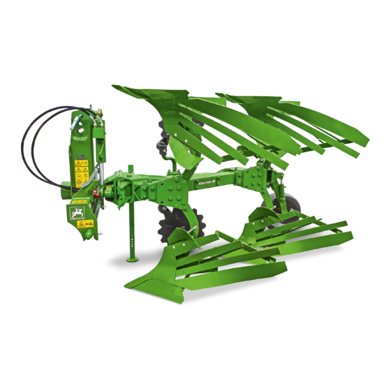
4 | Product description Product description CMS-T-00007827-C.1 4.1 Implement overview CMS-T-00007835-A.1 CMS-I-00005454 Beam Threaded cartridge Headstock Turning cylinder Adjustment unit of the hydraulic overload safety Implement rating plate Hydraulic overload safety Skimmer Plough body MG7349-EN-GB | D.1 | 09.02.2023 | © AMAZONE... - Page 25 4 | Product description Implement overview CMS-I-00005455 Transport lock Wrench Hose cabinet Adjustment Centre Parking support CMS-I-00005456 Disc coulter Working depth adjustment Depth and transport wheel MG7349-EN-GB | D.1 | 09.02.2023 | © AMAZONE...
-
Page 26: Function Of The Implement
Subsoiler point Scraper Packer arm for catch hooks Depth and transport wheel Quick-coupling adapter Swivelling beam LED rear lighting for road travel Hydraulic overload safety Semi-automatic overload safety Hydraulic working width adjustment MG7349-EN-GB | D.1 | 09.02.2023 | © AMAZONE... -
Page 27: Protective Device
4.4 Protective device CMS-T-00007830-A.1 The transport lock secures the implement in transport position. CMS-I-00005469 4.5 Rear lighting and identification for road travel CMS-T-00007829-A.1 Warning sign Rear lights, brake lights, and turn indicators CMS-I-00005470 MG7349-EN-GB | D.1 | 09.02.2023 | © AMAZONE... -
Page 28: Warning Symbols
M 241 M 24 M 240 M 082 M 096 MD097 M 102 MD199 M 155 M 078 M 078 CMS-I-00005468 M 079 M 108 CMS-I-00005467 MD155 M 27 M 078 CMS-I-00005466 MG7349-EN-GB | D.1 | 09.02.2023 | © AMAZONE... -
Page 29: Layout Of The Warning Symbols
If you have to move marked parts with your hands, pay attention to the crushing areas. CMS-I-000074 Make sure that there is nobody standing in the danger area. MG7349-EN-GB | D.1 | 09.02.2023 | © AMAZONE... - Page 30 Do not let anybody climb onto the driving implement. CMS-I-000081 MD095 Risk of accident due to non-compliance with the instructions in this operating manual Before your work on or with the implement, read and understand the operating manual. CMS-I-000138 MG7349-EN-GB | D.1 | 09.02.2023 | © AMAZONE...
- Page 31 Actuate the tractor hydraulic system only from the designated work station. CMS-I-000139 MD 102 Risk due to unintentional starting and rolling away of the machine Before performing any work, secure the implement against unintentional starting and rolling away. CMS-I-00002253 MG7349-EN-GB | D.1 | 09.02.2023 | © AMAZONE...
- Page 32 CMS-I-00000450 MD 199 Risk of accident if the hydraulic system pressure is too high Only couple the implement to tractors with a maximum tractor hydraulic pressure of 210 bar. CMS-I-00000486 MG7349-EN-GB | D.1 | 09.02.2023 | © AMAZONE...
-
Page 33: Rating Plate On The Implement
Make sure that there is nobody standing in the danger area. MD270 CMS-I-00005828 4.7 Rating plate on the implement CMS-T-00004505-G.1 Implement number Vehicle ID number Product Permissible technical implement weight Model year Year of manufacture CMS-I-00004294 MG7349-EN-GB | D.1 | 09.02.2023 | © AMAZONE... -
Page 34: Implement Positions
4.8 Implement positions CMS-T-00007831-A.1 CMS-I-00005471 Implement in working position Implement parked Implement in transport position 4.9 Plough body CMS-T-00006555-B.1 The plough bodies are selected depending on the soil properties and working conditions. MG7349-EN-GB | D.1 | 09.02.2023 | © AMAZONE... - Page 35 The front furrow width is affected by the following factors: Inner track width of the tractor Working width of the plough CMS-I-00002674 Tilt Working depth MG7349-EN-GB | D.1 | 09.02.2023 | © AMAZONE...
-
Page 36: Overload Safety
The hydraulic overload safety is available in two versions: The overload safety with central adjustment of the tripping force The overload safety with decentralised adjustment of the tripping force MG7349-EN-GB | D.1 | 09.02.2023 | © AMAZONE... -
Page 37: Semi-Automatic Overload Safety
CMS-T-00008091-A.1 With the semi-automatic overload safety, the plough bodies deflect against the pressure of two springs. The tripping force is adjusted with the spring preload and depends on the soil conditions. CMS-I-00005603 MG7349-EN-GB | D.1 | 09.02.2023 | © AMAZONE... -
Page 38: Turn-Over Bracket
To reduce the lifting height, the plough beam automatically swivels towards the centre of the tractor before turning the plough bodies. After turning, the plough beams swivels back to the set working width of the plough bodies. MG7349-EN-GB | D.1 | 09.02.2023 | © AMAZONE... -
Page 39: Depth And Transport Wheel
4.14 Adjustment Centre CMS-T-00007833-A.1 Cayros V Tilt adjustment Hydraulic front furrow width adjustment Pull point adjustment Hydraulic working width adjustment with or without swivelling beam and automatic pull point adjustment Working width display CMS-I-00005494 MG7349-EN-GB | D.1 | 09.02.2023 | © AMAZONE... -
Page 40: Disc Coulter
The landside coulter cuts a clean furrow on heavy or stony soils, and can replace the disc coulter. The landside coulter reduces wear on the plough body. CMS-I-00005784 MG7349-EN-GB | D.1 | 09.02.2023 | © AMAZONE... -
Page 41: Landside Protector
CMS-I-00004875 4.19 Trashboards CMS-T-00008520-A.1 Trashboards are suitable for incorporating crop residues. Trashboards prevent or reduce clogging. Trashboards are equipped with a support towards the plough leg. CMS-I-00005782 MG7349-EN-GB | D.1 | 09.02.2023 | © AMAZONE... -
Page 42: Subsoiler Point
The packer arm picks up the hook linkage of the packer roller. Packer catch hook with hydraulic release device Swivel adjustment CMS-I-00005733 Packer arm in transport position Packer arm in working position CMS-I-00005732 MG7349-EN-GB | D.1 | 09.02.2023 | © AMAZONE... -
Page 43: Threaded Cartridge
4 | Product description Threaded cartridge 4.22 Threaded cartridge CMS-T-00001776-E.1 The threaded cartridge contains the following items: Documents Aids CMS-I-00002306 MG7349-EN-GB | D.1 | 09.02.2023 | © AMAZONE... -
Page 44: Technical Data
30 cm 33 cm 33 cm 40 cm 30/40 cm working depth Maximu 50 cm 55 cm 50 cm 55 cm 50 cm 55 cm 55 cm 55 cm 50 cm working width MG7349-EN-GB | D.1 | 09.02.2023 | © AMAZONE... -
Page 45: Depth And Transport Wheel
5.3 Threaded spindle length for pull point adjustment CMS-T-00008201-B.1 5.3.1 Default dimension for manual working width adjustment CMS-T-00008202-B.1 NOTE The default dimensions are theoretical dimensions and can deviate from the real dimensions. MG7349-EN-GB | D.1 | 09.02.2023 | © AMAZONE... -
Page 46: Default Dimension With Hydraulic Working Width Adjustment
Cayros XS Pro 63.1 cm 61.1 cm 59.1 cm 57.1 cm 5.3.2 Default dimension with hydraulic working width adjustment CMS-T-00008203-B.1 NOTE The default dimensions are theoretical dimensions and can deviate from the real dimensions. MG7349-EN-GB | D.1 | 09.02.2023 | © AMAZONE... -
Page 47: Permitted Mounting Categories
5 plough body 88-132 kW / 103-180 kW / 132-240 kW / pairs 120-180 PS 140-245 PS 180-330 PS 6 plough body 118-206 kW / 162-279 kW / pairs 160-280 PS 220-380 PS MG7349-EN-GB | D.1 | 09.02.2023 | © AMAZONE... -
Page 48: Noise Development Data
On left in direction of travel 15 % On right in direction of travel 15 % Up the slope and down the slope Up the slope 15 % Down the slope 15 % MG7349-EN-GB | D.1 | 09.02.2023 | © AMAZONE... -
Page 49: Preparing The Machine
Total weight of front-mounted implement or front ballast Permissible total weight of rear-mounted implement or rear ballast Distance between the centre of gravity of the front-mounted implement or the front ballast and the centre of the front axle MG7349-EN-GB | D.1 | 09.02.2023 | © AMAZONE... - Page 50 T b 0,2 T b Vmin Vmin Vmin CMS-I-00000513 2. Calculate the actual front axle load. × × - × G a b T b G c + d Vtat Vtat Vtat CMS-I-00000516 MG7349-EN-GB | D.1 | 09.02.2023 | © AMAZONE...
- Page 51 Tyre load according to according to capacity for two tractor operating calculation tractor tyres manual ≤ Minimum front ballasting ≤ Total weight ≤ ≤ Front axle load ≤ ≤ Rear axle load MG7349-EN-GB | D.1 | 09.02.2023 | © AMAZONE...
-
Page 52: Coupling The Implement
Keep the stop tap of the hydraulic overload safety closed. Maintain the pre-tension on the plough body unit of the overload safety. 6.2.3 Preparing the headstock CMS-T-00007809-A.1 NOTE Use a ball sleeve without integrated catch profile. MG7349-EN-GB | D.1 | 09.02.2023 | © AMAZONE... -
Page 53: Driving The Tractor Towards The Implement
Stickers are applied on the implement for the markings, which illustrate the respective hydraulic functions. The tractor control unit is used with different types of actuation, depending on the hydraulic function: CMS-I-00000121 MG7349-EN-GB | D.1 | 09.02.2023 | © AMAZONE... - Page 54 Risk of injury or even death If the hydraulic hose lines are incorrectly connected, the hydraulic functions may be faulty. When coupling the hydraulic hose lines, observe the coloured markings on the hydraulic plugs. MG7349-EN-GB | D.1 | 09.02.2023 | © AMAZONE...
-
Page 55: Coupling The Power Supply
2. Drive the tractor towards the implement. 3. Couple the tractor lower links from the tractor seat. 4. Check whether the lower link catch hooks 2 are correctly locked. 5. Lock the tractor lower links laterally. CMS-I-00003346 MG7349-EN-GB | D.1 | 09.02.2023 | © AMAZONE... -
Page 56: Lifting The Parking Support
3. Check whether the top link catch hooks 2 is CMS-I-00003706 correctly locked. 4. Adjust the top link length so that the pin rests at the front of the slot. 5. Lift the implement using the 3-point hitch. CMS-I-00005142 MG7349-EN-GB | D.1 | 09.02.2023 | © AMAZONE... -
Page 57: Moving The Depth And Transport Wheel Into Transport Position
2 . 6. Secure the damping cylinder with the linch pin CMS-I-00005607 7. Pull out the pin. 8. Lift the depth and transport wheel and swivel into transport position. CMS-I-00005502 MG7349-EN-GB | D.1 | 09.02.2023 | © AMAZONE... -
Page 58: Moving The Plough Body Into Transport Position
8. Uncouple the unloaded top link. 9. For road transport, lift the implement as far as it goes using the tractor lower links. MG7349-EN-GB | D.1 | 09.02.2023 | © AMAZONE... -
Page 59: Installing The Rear Lighting
3. Insert the plug for the power supply into the socket. CMS-I-00005499 6.3 Preparing the implement for operation CMS-T-00007811-C.1 6.3.1 Preparing for initial operation CMS-T-00008453-D.1 6.3.1.1 Calculating the required tractor characteristics CMS-T-00000063-E.1 CMS-I-00000581 MG7349-EN-GB | D.1 | 09.02.2023 | © AMAZONE... - Page 60 Distance between the centre of the rear axle and the centre of the lower link connection Centre of gravity distance: Distance between the centre of the lower link coupling point and centre of gravity of the rear-mounted implement or rear ballast. MG7349-EN-GB | D.1 | 09.02.2023 | © AMAZONE...
- Page 61 T b G c + d Vtat Vtat Vtat CMS-I-00000516 3. Calculate the actual total weight of the tractor- implement combination. CMS-I-00000515 4. Calculate the actual rear axle load. Htat Vtat Htat Htat CMS-I-00000514 MG7349-EN-GB | D.1 | 09.02.2023 | © AMAZONE...
- Page 62 4. Adjust the tyre inflation pressure of the front wheels equally on both sides. 5. Adjust the tyre inflation pressure of the rear wheels equally on both sides. CMS-I-00006537 NOTE The required tyre load capacity must be ensured. MG7349-EN-GB | D.1 | 09.02.2023 | © AMAZONE...
- Page 63 1. Put the hand lever on the hydraulic accumulator. 2. Open the hydraulic accumulator with the hand lever. 3. Then fasten the hand lever in parking position with the spring cotter pin. CMS-I-00005510 MG7349-EN-GB | D.1 | 09.02.2023 | © AMAZONE...
-
Page 64: Hydraulic Adjustment Of The Plough Body Working Width
With the hydraulic working width adjustment of the plough bodies, the leading tools and the support wheel are automatically also adjusted. Moreover, the pull point and the front furrow width are also automatically adjusted. MG7349-EN-GB | D.1 | 09.02.2023 | © AMAZONE... -
Page 65: Manual Adjustment Of The Working Width Of The Plough Bodies
CMS-I-00002675 1. Lift the implement slightly using the 3-point hitch. 2. Loosen the bolt 1 . 3. Release and remove the bolt 2 . CMS-I-00005503 MG7349-EN-GB | D.1 | 09.02.2023 | © AMAZONE... -
Page 66: Adjusting The Pull Point
To prevent lateral pull, the landside 2 of the plough body must be aligned with the direction of travel. 90° CMS-I-00005516 NOTE Cayros V: After adjusting the working width, the pull point does not need to be adjusted. CMS-I-00005522 MG7349-EN-GB | D.1 | 09.02.2023 | © AMAZONE... -
Page 67: Adjusting The Front Furrow Width
To adjust the front furrow width, actuate the "yellow" tractor control unit. 3. During operation, stop and relieve the guide if necessary. Correct the setting. MG7349-EN-GB | D.1 | 09.02.2023 | © AMAZONE... -
Page 68: Relative To The Tractor
To do so, the tilt of the plough to the tractor must be adjusted. The stop can be adjusted with the spindles and determines the tilt angle. The tilt angle depends on the adjusted working depth. 90° CMS-I-00003708 MG7349-EN-GB | D.1 | 09.02.2023 | © AMAZONE... -
Page 69: Adjusting The Plough Body Working
Cayros XMS, XS, XS pro CMS-I-00005514 6.3.7 Adjusting the plough body working depth CMS-T-00007812-A.1 Adjust the plough body working depth equally on both sides using the threaded spindles on the wheel. MG7349-EN-GB | D.1 | 09.02.2023 | © AMAZONE... -
Page 70: Depth
2. Swivel the disc coulter up or down. CMS-I-00004928 3. Retighten the bolted connection. 4. Check that the teeth are properly seated. 5. Adjust both disc coulters at the same working depth. MG7349-EN-GB | D.1 | 09.02.2023 | © AMAZONE... - Page 71 4. Adjust the disc coulter equally on both sides. CMS-I-00004926 6.3.8.3 Adjusting the swivelling range of the disc coulter CMS-T-00007007-B.1 The disc coulter can turn freely around its vertical axis within the adjusted range. MG7349-EN-GB | D.1 | 09.02.2023 | © AMAZONE...
-
Page 72: Preparing The Skimmers For Operation
5. Adjust the working depth and then tighten the locking bolt 3 . CMS-I-00003720 6. Tighten the locking bolt 1 . 7. Lock all of the bolts with nuts. 8. Adjust all skimmers to the same working depth. MG7349-EN-GB | D.1 | 09.02.2023 | © AMAZONE... - Page 73 8. Loosen the bolts 5 . 9. Adjust the horizontal position of the pull-in force of the skimmer. The skimmer protrudes from the plough body by 1.5 to 2 cm. 10. Tighten the bolts 5 . MG7349-EN-GB | D.1 | 09.02.2023 | © AMAZONE...
-
Page 74: Adjusting The Tripping Force Of The Hydraulic Overload Safety
To set the tripping force of the hydraulic CMS-I-00005511 overload safety simultaneously for all plough bodies, Actuate the "beige" tractor control unit. Select a pre-tension between 80 and 180 bar. Default value: 100 bar MG7349-EN-GB | D.1 | 09.02.2023 | © AMAZONE... - Page 75 Always maintain pressure on the hydraulic overload safety. 1. Couple the hydraulic unit 1 to the tractor control unit. 2. Connect the hydraulic unit to the hydraulic accumulator 2 of the hydraulic overload safety. CMS-I-00005547 MG7349-EN-GB | D.1 | 09.02.2023 | © AMAZONE...
-
Page 76: Setting The Tripping Force For The Semi-Automatic Overload Safety
6.3.11 Setting the tripping force for the semi-automatic overload safety CMS-T-00007954-B.1 The tripping force of the semi-automatic overload safety can be infinitely variably adjusted to suit the soil conditions. Default spring length L = 20 cm MG7349-EN-GB | D.1 | 09.02.2023 | © AMAZONE... -
Page 77: Moving The Implement Into Working Position
1. Insert the plug for the power supply into the socket. 2. Loosen and remove both bolts. 3. Pull the rear lighting out of the mount. 4. Store the rear lighting in a suitable place. CMS-I-00005499 MG7349-EN-GB | D.1 | 09.02.2023 | © AMAZONE... -
Page 78: Coupling The Top Link
To swivel the plough bodies into working position, Actuate the "green" tractor control unit. 5. Swivel the plough body to the right so that the control elements of the wheel are accessible. MG7349-EN-GB | D.1 | 09.02.2023 | © AMAZONE... -
Page 79: Swivelling The Depth And Transport Wheel Into Working Position
1. Pull out the pin. 2. Swivel the depth and transport wheel into working position. CMS-I-00005509 3. Secure the depth and transport wheel with the pin. 4. Secure the pin with a linch pin. CMS-I-00005508 MG7349-EN-GB | D.1 | 09.02.2023 | © AMAZONE... -
Page 80: Swivelling The Packer Arm Into Working Position
1. Take the pin 1 out of the swivel adjustment. 2. Swivel the packer arm 2 outwards according to the utilised packer roller. To secure the packer arm in position, insert the pin 3 in the swivel adjustment. CMS-I-00005731 MG7349-EN-GB | D.1 | 09.02.2023 | © AMAZONE... -
Page 81: Installing The Scraper For The Depth And Transport Wheel In Working Position
Always maintain pressure on the overload safety. Keep the stop tap of the hydraulic overload safety closed. Maintain the pre-tension on the plough body unit of the overload safety. MG7349-EN-GB | D.1 | 09.02.2023 | © AMAZONE... -
Page 82: Swivelling The Packer Arm Into Transport Position
1. Remove the bolt 1 . 2. Take the scraper out from the working position 3. Insert the scraper in the mount 2 in transport position 3 . 4. Tighten the bolt. CMS-I-00007402 MG7349-EN-GB | D.1 | 09.02.2023 | © AMAZONE... -
Page 83: Moving The Depth And Transport Wheel Into Transport Position
2 . 6. Secure the damping cylinder with the linch pin CMS-I-00005607 7. Pull out the pin. 8. Lift the depth and transport wheel and swivel into transport position. CMS-I-00005502 MG7349-EN-GB | D.1 | 09.02.2023 | © AMAZONE... -
Page 84: Moving The Plough Body Into Transport Position
8. Uncouple the unloaded top link. 9. For road transport, lift the implement as far as it goes using the tractor lower links. MG7349-EN-GB | D.1 | 09.02.2023 | © AMAZONE... -
Page 85: Installing The Rear Lighting
6.5.7 Installing the rear lighting CMS-T-00007804-A.1 1. Insert the rear lighting in the mount. 2. Secure the rear lighting with 2 bolts. 3. Insert the plug for the power supply into the socket. CMS-I-00005499 MG7349-EN-GB | D.1 | 09.02.2023 | © AMAZONE... -
Page 86: Using The Implement
1. Lower the implement using the lower link. 2. Select the top link coupling point. 3. Couple the top link 1 . 4. Check whether the top link catch hooks 2 is correctly locked. CMS-I-00003706 MG7349-EN-GB | D.1 | 09.02.2023 | © AMAZONE... -
Page 87: Unlocking The Depth And Transport Wheel
To swivel the plough bodies into working position, Actuate the "green" tractor control unit. CMS-I-00005221 To reach the control elements of the depth and transport wheel, the plough body must be swivelled to the right. MG7349-EN-GB | D.1 | 09.02.2023 | © AMAZONE... -
Page 88: Swivelling The Depth And Transport Wheel Into Working Position
7. Secure the 30 mm pin with a linch pin. CMS-I-00005228 8. Lower the implement into working position using the 3-point hitch. To align the depth and transport wheel correctly, drive the implement slightly forwards. CMS-I-00005229 MG7349-EN-GB | D.1 | 09.02.2023 | © AMAZONE... -
Page 89: Mounting The Scraper For The Depth And Transport Wheel
2. Take the scraper for the depth and transport wheel from the parking position. 3. Refasten the linch pin. 4. Loosen the bolt 1 . 5. Install the scraper for the depth and transport wheel. 6. Tighten the bolt. CMS-I-00005231 MG7349-EN-GB | D.1 | 09.02.2023 | © AMAZONE... -
Page 90: Swivelling The Packer Arm Into Working Position
3 in the swivel adjustment. CMS-I-00005731 7.8 Releasing the lateral locking of the tractor lower links CMS-T-00008119-A.1 To allow the plough to freely align itself during operation, release the lateral locking of the tractor lower links. MG7349-EN-GB | D.1 | 09.02.2023 | © AMAZONE... -
Page 91: Hydraulic Adjustment Of The Plough Body Working Width
When turning with the maximum front furrow width, the plough bodies can collide with the beam. Before you turn the plough bodies, make sure that the front furrow width is not set at the maximum. MG7349-EN-GB | D.1 | 09.02.2023 | © AMAZONE... -
Page 92: Using The Implement
4. Correct the adjustment during operation if necessary. 7.11 Using the implement CMS-T-00007341-F.1 1. Lower the implement on the field. 2. Start ploughing. 3. Align the implement horizontally via the 3-point hitch. 4. Correct the settings. MG7349-EN-GB | D.1 | 09.02.2023 | © AMAZONE... -
Page 93: Turning On The Headlands
To turn the plough bodies, Actuate the "green" tractor control unit. 3. After the headlands, align the implement horizontally to the ground using the 3-point hitch. 4. Check the adjustment after the second furrow. MG7349-EN-GB | D.1 | 09.02.2023 | © AMAZONE... -
Page 94: Eliminating Faults
The plough body swivels back into working position. To release the transport lock, Transport lock cannot be unlocked The hand lever does not unlock the transport lock. actuate the "green" tractor control unit on both sides. MG7349-EN-GB | D.1 | 09.02.2023 | © AMAZONE... - Page 95 Maintain a safe distance from the plough body. 1. Swivel the plough body back into working position. CMS-I-00005761 2. If the plough body is blocked, loosen the bolt at the pivot point 2 . MG7349-EN-GB | D.1 | 09.02.2023 | © AMAZONE...
- Page 96 Cayros XS DB667 M16x72 10.9 Cayros XS Pro DB673 M16x80 10.9 1. Stop working. 2. Drive a short distance in reverse. 3. The plough body swivels back into working position. MG7349-EN-GB | D.1 | 09.02.2023 | © AMAZONE...
-
Page 97: Parking The Implement
Select the coupling point on the implement side such that it is slightly higher than the coupling point on the tractor side, even during operation. 3. Check whether the top link catch hooks 2 is CMS-I-00003706 correctly locked. MG7349-EN-GB | D.1 | 09.02.2023 | © AMAZONE... -
Page 98: Aligning The Implement Horizontally
NOTE Before swivelling the plough bodies into working position, set the tilt angle on the right from 90° back to the working value if necessary, see page 62. MG7349-EN-GB | D.1 | 09.02.2023 | © AMAZONE... -
Page 99: Removing The Subsoiler Point
9.5 Removing the subsoiler point CMS-T-00008047-A.1 To park the plough in working position, the subsoiler points on the lower plough body pairs must be removed. 1. Loosen the bolts. 2. Remove the subsoiler point. CMS-I-00005567 MG7349-EN-GB | D.1 | 09.02.2023 | © AMAZONE... -
Page 100: Swivelling The Depth And Transport Wheel Into Working Position
1. Pull out the pin. 2. Swivel the depth and transport wheel into working position. CMS-I-00005509 3. Secure the depth and transport wheel with the pin. 4. Secure the pin with a linch pin. CMS-I-00005508 MG7349-EN-GB | D.1 | 09.02.2023 | © AMAZONE... -
Page 101: Uncoupling The Top Link
CMS-T-00007841-A.1 1. Slightly lift the implement slightly via the tractor lower link. 2. Remove the linch pin. 3. Lower the parking support. 4. Secure the parking support with the linch pin. CMS-I-00005496 MG7349-EN-GB | D.1 | 09.02.2023 | © AMAZONE... -
Page 102: Uncoupling The Lower Link
Drive the tractor away from the implement, leaving a sufficient distance. CMS-I-00004045 9.11 Uncoupling the power supply CMS-T-00001402-H.1 1. Pull out the plug 1 for the power supply. CMS-I-00001048 MG7349-EN-GB | D.1 | 09.02.2023 | © AMAZONE... -
Page 103: Disconnecting The Hydraulic Hose Lines
3. Disconnect the hydraulic hose lines 1 . 4. Put the dust caps on the hydraulic sockets. CMS-I-00001065 5. Hang the hydraulic hose lines 1 in the hose cabinet. CMS-I-00001250 MG7349-EN-GB | D.1 | 09.02.2023 | © AMAZONE... -
Page 104: Repairing The Implement
Every 1000 operating hours / Every 12 months Checking the hub bearing see page 102 Checking the semi-automatic overload safety see page 103 Checking the pressure on the hydraulic accumulator see page 103 of the hydraulic overload safety MG7349-EN-GB | D.1 | 09.02.2023 | © AMAZONE... -
Page 105: Checking The Hydraulic Hose Lines
Hydraulic hose lines must not be more than 6 years old. 3. Check the manufacturing date 1 . CMS-I-00000532 4. Have any worn, damaged or aged hydraulic hose lines immediately replaced at a specialist workshop. 5. Retighten loose bolted connections. MG7349-EN-GB | D.1 | 09.02.2023 | © AMAZONE... -
Page 106: Checking The Condition Of Wear Parts
CMS-I-00004513 Skimmer share Exchange coulter tip Wing Landside point Landside CMS-I-00004531 Not illustrated: Trashboard Deflector plate Subsoiler point 1. Check the condition of wear parts. 2. Replace wear parts that are worn. MG7349-EN-GB | D.1 | 09.02.2023 | © AMAZONE... -
Page 107: Checking The Bolted Connections
M12x40 12.9 M14x39 12.9 230 Nm CMS-I-00003760 10.1.5 Checking the wheel CMS-T-00008042-B.1 INTERVAL as required There are stickers attached in the rim of the wheels, which specify the required tyre inflation pressure. MG7349-EN-GB | D.1 | 09.02.2023 | © AMAZONE... -
Page 108: Checking The Hub Bearing
10.1.7 Checking the top link pin and lower link pin CMS-T-00002330-H.1 INTERVAL daily 1. Check the top link pins and lower link pins for cracks or broken areas. Permissible wear 2 mm 2. Replace the pins if there is significant wear. MG7349-EN-GB | D.1 | 09.02.2023 | © AMAZONE... -
Page 109: Checking The Semi-Automatic Overload Safety
CMS-T-00008052-B.1 INTERVAL Every 1000 operating hours Every 12 months Have the pressure on the hydraulic accumulator of the hydraulic overload safety checked by a qualified specialist workshop. Preload pressure: 100 bar MG7349-EN-GB | D.1 | 09.02.2023 | © AMAZONE... -
Page 110: Lubricating The Implement
Only grease the implement with the lubricants listed in the technical data. CMS-I-00002270 Press the dirty grease completely out of the bearings. MG7349-EN-GB | D.1 | 09.02.2023 | © AMAZONE... -
Page 111: Overview Of Lubrication Points
10 | Repairing the implement Lubricating the implement 10.2.1 Overview of lubrication points CMS-T-00008076-A.1 CMS-I-00005570 Every 50 operating hours CMS-I-00005580 CMS-I-00005578 CMS-I-00005579 CMS-I-00005596 MG7349-EN-GB | D.1 | 09.02.2023 | © AMAZONE... - Page 112 10 | Repairing the implement Lubricating the implement CMS-I-00005576 CMS-I-00005597 CMS-I-00005577 CMS-I-00005575 CMS-I-00005574 CMS-I-00005598 CMS-I-00005573 CMS-I-00005581 MG7349-EN-GB | D.1 | 09.02.2023 | © AMAZONE...
-
Page 113: Cleaning The Implement
10.4 Storing the implement CMS-T-00005282-A.1 IMPORTANT Implement damage due to corrosion Dirt attracts moisture and leads to corrosion. Store the implement only in a clean state and protected from the weather. MG7349-EN-GB | D.1 | 09.02.2023 | © AMAZONE... - Page 114 Storing the implement 1. Clean the machine. 2. Protect unpainted components from corrosion using a suitable corrosion inhibitor. 3. Grease all lubrication points. Remove excess grease. 4. Park the implement in a sheltered place. MG7349-EN-GB | D.1 | 09.02.2023 | © AMAZONE...
-
Page 115: Loading The Implement
If the slings are not attached at the marked lashing points, the implement can be damaged during lifting and endanger safety. Only attach the slings for lifting at the marked lashing points. MG7349-EN-GB | D.1 | 09.02.2023 | © AMAZONE... -
Page 116: Lashing The Implement
1. Put the implement on the transport vehicle. 2. Attach the lashing straps at the marked points. 3. Lash down the implement in compliance with the national regulations for load securing. MG7349-EN-GB | D.1 | 09.02.2023 | © AMAZONE... -
Page 117: Appendix
380 Nm 290 Nm 405 Nm 485 Nm 27 mm M18x1.5 325 Nm 460 Nm 550 Nm 410 Nm 580 Nm 690 Nm 30 mm M20x1.5 460 Nm 640 Nm 770 Nm MG7349-EN-GB | D.1 | 09.02.2023 | © AMAZONE... -
Page 118: Other Applicable Documents
2.4 Nm 112 Nm 4.9 Nm 174 Nm 8.4 Nm 242 Nm 20.4 Nm 342 Nm 40.7 Nm 470 Nm 70.5 Nm 589 Nm 12.2 Other applicable documents CMS-T-00006213-A.1 Tractor operating manual MG7349-EN-GB | D.1 | 09.02.2023 | © AMAZONE... -
Page 119: Disposing Of The Implement
2. Return batteries to the distributor Dispose of batteries at a collection point. 3. Put recyclable materials in the recycling. 4. Treat operating materials like hazardous waste. 5. Have coolants disposed of by a specialist workshop. MG7349-EN-GB | D.1 | 09.02.2023 | © AMAZONE... -
Page 120: Directories
Tractor In this operating manual, the designation tractor is always used, even for other agricultural tractor units. Implements are mounted on the tractor or towed by the tractor. MG7349-EN-GB | D.1 | 09.02.2023 | © AMAZONE... -
Page 121: Index
Adjusting the lateral distance Initial operation Adjusting the swivelling range Configuring the operating hours counter Adjust the working depth Preparing the tractor Description Intended use Documents Landside coulter Error eliminating Landside protector MG7349-EN-GB | D.1 | 09.02.2023 | © AMAZONE... - Page 122 74, 84 Shear bolt Parking support replacing lowering Position Skimmer raising Adjusting the working angle Description Position Working depth Special equipment MG7349-EN-GB | D.1 | 09.02.2023 | © AMAZONE...
- Page 123 Position checking Total weight calculation 43, 53 Tractor Calculating the required tractor characteristics 43, 53 Tractor lower link coupling Transport lock Position Transport mit Kran verladen Transport speed Trashboard Turning cylinder Position MG7349-EN-GB | D.1 | 09.02.2023 | © AMAZONE...
- Page 126 AMAZONEN-WERKE H. DREYER SE & Co. KG Postfach 51 49202 Hasbergen-Gaste Germany +49 (0) 5405 501-0 amazone@amazone.de www.amazone.de MG7349-EN-GB | D.1 | 09.02.2023 | © AMAZONE...
Need help?
Do you have a question about the Cayros M and is the answer not in the manual?
Questions and answers