Amazone Cayros M Original Operating Manual
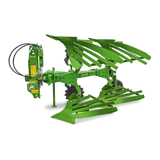
Mounted reversible plough with pendulum support wheel / double support wheel / without support wheel
Hide thumbs
Also See for Cayros M:
- Operating manual (68 pages) ,
- Original operating manual (126 pages)
Table of Contents
Advertisement
Quick Links
Advertisement
Table of Contents

Related Manuals for Amazone Cayros M


Summary of Contents for Amazone Cayros M
- Page 1 Original operating manual Mounted reversible plough with pendulum support wheel / double support wheel / without support wheel Cayros M Cayros M V Cayros XM Cayros XM V Cayros XMS Cayros XMS V Cayros XS Cayros XS V Cayros XS-Pro...
- Page 2 Please enter the identification data of the implement. The identification data can be found on the rating plate.
-
Page 3: Table Of Contents
TABLE OF CONTENTS TABLE OF CONTENTS 4.8.2 Hydraulic overload safety 1 About this operating manual 4.8.3 Semi-automatic overload safety Diagrams Turn-over bracket 1.1.1 Warnings and signal words 4.10 Swivelling beam 1.1.2 Further instructions 4.11 Support wheel 1.1.3 Instructions 4.12 Adjustment Centre 1.1.4 Lists 4.13... - Page 4 TABLE OF CONTENTS 6.1.2 Preparing the tractor 6.4.4 Swivelling the packer arm into transport position 6.1.3 Removing the protective varnish 6.1.4 Preparing the central overload safety 6.1.5 Configuring the operating hours 7 Using the implement counter Releasing the lateral locking of Coupling the implement the tractor lower links 6.2.1...
- Page 5 TABLE OF CONTENTS 10.1.9 Checking the hydraulic overload safety 10.1.10 Checking the pressure on the hydraulic accumulator of the hydraulic overload safety 10.2 Lubricating the implement 10.2.1 Overview of lubrication points 10.3 Cleaning the implement 10.4 Storing the implement 11 Loading the implement 11.1 Lifting the implement 11.2...
-
Page 7: About This Operating Manual
1 | About this operating manual About this operating manual CMS-T-00000081-D.1 1.1 Diagrams CMS-T-005676-C.1 1.1.1 Warnings and signal words CMS-T-00002415-A.1 Warnings are marked with a vertical bar with a triangular safety symbol and the signal word. The signal words "DANGER", "WARNING" or "CAUTION" describe the severity of the potential danger and have the following meanings: DANGER... -
Page 8: Instructions
1 | About this operating manual Diagrams ENVIRONMENTAL INFORMATION Indicates a risk for environmental damage. NOTE Indicates application tips and instructions for optimal use. 1.1.3 Instructions CMS-T-00000473-B.1 Numbered instructions CMS-T-005217-B.1 Actions that have to be performed in a specific sequence are represented as numbered instructions. The specified sequence of the actions must be observed. -
Page 9: Lists
1 | About this operating manual Diagrams Example: 1. Instruction 1 Alternative instruction 2. Instruction 2 Instructions with only one action CMS-T-005211-C.1 Instructions with only one action are not numbered, but rather shown with a arrow. Example: Instruction Instructions without sequence CMS-T-005214-C.1 Instructions that do not require a specific sequence are shown as a list with arrows. -
Page 10: Other Applicable Documents
Your suggestions for improvement help us Technische Redaktion to create ever more user-friendly operating manuals. Postfach 51 Please send us your suggestions by post, fax or D-49202 Hasbergen email. Fax: +49 (0) 5405 501-234 E-Mail: td@amazone.de MG7364-EN-II | B.1 | 07.04.2022... -
Page 11: Safety And Responsibility
2 | Safety and responsibility Safety and responsibility CMS-T-00005276-C.1 2.1 Basic safety instructions CMS-T-00005277-C.1 2.1.1 Meaning of the operating manual CMS-T-00006180-A.1 Observe the operating manual The operating manual is an important document and a part of the implement. It is intended for the user and contains safety-related information. - Page 12 2 | Safety and responsibility Basic safety instructions the machine must meet the following minimum requirements: The person is physically and mentally capable of controlling the machine. The person can safely perform work with the machine within the scope of this operating manual.
- Page 13 2 | Safety and responsibility Basic safety instructions Farmers can be e.g.: Farmers with higher education or training from a technical college Farmers by experience (e.g. inherited farm, comprehensive practical knowledge) Contractors who work by order of farmers Activity example: Safety training for agricultural helpers 2.1.2.1.4 Agricultural helpers CMS-T-00002313-A.1...
- Page 14 2 | Safety and responsibility Basic safety instructions 2.1.2.3 Danger for children CMS-T-00002308-A.1 Danger for children Children cannot assess dangerous situations and can behave unpredictably. As a result, children are at a higher risk. Keep children away. When you drive out or actuate machine movements, make sure that there are no children in the danger area.
- Page 15 2 | Safety and responsibility Basic safety instructions 2.1.2.4.2 Personal protective equipment CMS-T-00002316-B.1 Personal protective equipment Wearing personal protective equipment is an important safety element. Missing or unsuitable personal protective equipment increases the risk of damage to health and personal injury. Personal protective equipment includes: work gloves, safety shoes, protective clothing, breathing protection, hearing protection, face protection, and eye protection Determine the personal protective equipment required for each job and have it ready.
-
Page 16: Recognising And Preventing Dangers
2 | Safety and responsibility Basic safety instructions 2.1.3 Recognising and preventing dangers CMS-T-00005278-A.1 2.1.3.1 Safety hazards on the machine CMS-T-00002318-D.1 Liquids under pressure Escaping high pressure hydraulic fluid can penetrate into the body through the skin and cause serious personal injuries. -
Page 17: Safe Operation And Handling Of The Machine
2 | Safety and responsibility Basic safety instructions 2.1.3.2 Danger areas CMS-T-00005280-A.1 Dangers areas on the implement The following basic dangers are encountered in the danger areas: The implement and its work tools move during operation. Hydraulically raised implement parts can descend unnoticed and slowly. - Page 18 2 | Safety and responsibility Basic safety instructions 2.1.4.2 Driving safety CMS-T-00002321-D.1 Risk when driving on roads and fields Any mounted or towed implement as well as front or rear ballast weights on the tractor influence the driving behaviour and the steering and braking power of the tractor. The driving characteristics also depend on the operating condition, the fill level of the load, and on the ground.
-
Page 19: Safe Maintenance And Modification
Have any design changes and extensions performed only by a qualified specialist workshop. To ensure that the operating permit remains valid in accordance with national and international regulations, ensure that the specialist workshop only uses conversion parts, spare parts and special equipment approved by AMAZONE. MG7364-EN-II | B.1 | 07.04.2022... - Page 20 2 | Safety and responsibility Basic safety instructions 2.1.5.2 Work on the machine CMS-T-00002323-C.1 Only work on the machine when it is at a standstill If the machine is not standing still, part can move unintentionally or the machine can be set in motion. This can result in serious injury or death.
- Page 21 2 | Safety and responsibility Basic safety instructions Maintenance work Improper maintenance work, particularly on safety-related components, endangers operational safety. This can result in accidents and serious personal injury or even death. Safety-related components include, for example, hydraulic components, electronic components, frames, springs, trailer coupling, axles and axle suspensions, lines and tanks containing flammable substances.
- Page 22 CMS-T-00002325-B.1 Special equipment, accessories, and spare parts Special equipment, accessories, and spare parts that do not meet AMAZONE requirements can impede the operational safety of the implement and cause accidents. Only use original parts or parts that meet AMAZONE requirements.
-
Page 23: Intended Use
Further instructions for intended use in special cases can be requested from AMAZONE. Uses other than those specified under the intended use are considered as improper. The manufacturer is not liable for any damage resulting from improper use, solely the operator is responsible. -
Page 24: Product Description
4 | Product description Product description CMS-T-00008108-A.1 4.1 Implement overview CMS-T-00008112-A.1 CMS-I-00005454 Beam Implement rating plate Threaded cartridge Hydraulic overload safety Headstock Skimmer Turning cylinder Plough body Adjustment unit of the hydraulic overload safety MG7364-EN-II | B.1 | 07.04.2022... -
Page 25: Implement Overview
4 | Product description Implement overview CMS-I-00005609 Wrench Adjustment Centre Hose cabinet Parking support CMS-I-00005610 Disc coulter Pendulum support wheel Working depth adjustment MG7364-EN-II | B.1 | 07.04.2022... -
Page 26: Function Of The Implement
4 | Product description Function of the implement 4.2 Function of the implement CMS-T-00007837-A.1 The mounted reversible plough has the following functions: The plough is an agricultural implement for loosening and turning over arable soil in the tillage horizon area. A plough can turn the soil to the right or to the left. -
Page 27: Rear Lighting And Identification
4 | Product description Rear lighting and identification for road travel 4.4 Rear lighting and identification for road travel CMS-T-00008113-A.1 Warning sign Rear lights, brake lights, and turn indicators CMS-I-00005611 4.5 Warning symbols CMS-T-00007834-B.1 4.5.1 Positions of the warning symbols CMS-T-00007862-B.1 M 241 M 24... -
Page 28: Layout Of The Warning Symbols
4 | Product description Warning symbols M 079 M 108 CMS-I-00005467 MD155 M 27 M 078 CMS-I-00005466 MD078 CMS-I-00005763 4.5.2 Layout of the warning symbols CMS-T-000141-D.1 Warning symbols indicate danger areas on the machine and warn against residual dangers. In these danger areas, there are permanent or unexpected dangers. -
Page 29: Description Of The Warning Symbols
4 | Product description Warning symbols 4.5.3 Description of the warning symbols CMS-T-00007863-A.1 MD 078 Risk of crushing fingers or hands As long as the tractor engine or implement motor is running, stay away from the danger area. If you have to move marked parts with your hands, pay attention to the crushing areas. - Page 30 4 | Product description Warning symbols MD095 Risk of accident due to non-compliance with the instructions in this operating manual Before your work on or with the implement, read and understand the operating manual. CMS-I-000138 MD 096 Risk of infection from escaping hydraulic fluid under high pressure Never look for leaks in hydraulic hose lines using your hand or fingers.
- Page 31 4 | Product description Warning symbols MD 102 Risk due to unintentional starting and rolling away of the machine Before performing any work, secure the implement against unintentional starting and rolling away. CMS-I-00002253 MD 108 Severe injuries due to incorrect handling of the hydraulic accumulator when it is under pressure Have the pressurised hydraulic accumulator checked and repaired only by a qualified...
- Page 32 4 | Product description Warning symbols MD 199 Risk of accident if the hydraulic system pressure is too high Only couple the implement to tractors with a maximum tractor hydraulic pressure of 210 bar. CMS-I-00000486 MD 240 Risk of accident when driving on roads due to incorrect preparation of the implement Prepare the implement properly for road travel.
-
Page 33: Rating Plate On The Implement
4 | Product description Rating plate on the implement 4.6 Rating plate on the implement CMS-T-00004505-F.1 Implement number Vehicle ID number Product Permissible technical implement weight Model year Year of manufacture CMS-I-00004294 4.7 Plough body CMS-T-00006555-B.1 The plough bodies are selected depending on the soil properties and working conditions. -
Page 34: Overload Safety
4 | Product description Overload safety Working width of the plough body The working width is the actual cutting width of a plough body, measured at 90° to the direction of travel. CMS-I-00002675 Front furrow width The front furrow width is measured from the furrow edge to the landside of the first plough body. -
Page 35: Hydraulic Overload Safety
4 | Product description Overload safety 4.8.2 Hydraulic overload safety CMS-T-00003656-C.1 With the overload safety, the plough bodies deflect in case of overload. Each plough body can deflect upwards or to the side individually. The pressurised hydraulic system guides the plough body back into working position. -
Page 36: Turn-Over Bracket
4 | Product description Turn-over bracket 4.9 Turn-over bracket CMS-T-00008110-A.1 The turn-over bracket 1 turns the plough bodies from one side to the other on the headlands. The end position of the turn-over bracket determines the tilt of the plough. In the end position, the turn-over bracket rests on the adjustable stop 2 . -
Page 37: Support Wheel
4 | Product description Support wheel 4.11 Support wheel CMS-T-00008109-A.1 The support wheel is used for depth control of the plough bodies. Pendulum support wheel, rear Working depth adjustment of the plough bodies Damper cylinder CMS-I-00005613 Pendulum support wheel, centre Adjustable swivelling range Working depth adjustment of the plough bodies Damper cylinder... -
Page 38: Adjustment Centre
4 | Product description Adjustment Centre Double support wheel Working depth adjustment of the plough bodies CMS-I-00005612 4.12 Adjustment Centre CMS-T-00007833-A.1 Cayros V Tilt adjustment Hydraulic front furrow width adjustment Pull point adjustment Hydraulic working width adjustment with or without swivelling beam and automatic pull point adjustment Working width display CMS-I-00005494... -
Page 39: Disc Coulter
4 | Product description Disc coulter Cayros Tilt adjustment Manual front furrow width adjustment Swivelling beam Pull point adjustment Manual working width adjustment CMS-I-00005493 4.13 Disc coulter CMS-T-00008442-A.1 The disc coulter produces a defined furrow edge. The working depth and the distance from the disc coulter to the plough body can be adjusted. -
Page 40: Landside Protector
4 | Product description Landside protector 4.15 Landside protector CMS-T-00006966-C.1 The landside protector is installed on the landside and increases its service life. The landside protector gives the plough more secure lateral footing on slopes. CMS-I-00004882 4.16 Skimmer CMS-T-00006964-B.1 The skimmer is suitable for ploughing up grassland and for incorporation crop residues. -
Page 41: Subsoiler Point
4 | Product description Subsoiler point 4.18 Subsoiler point CMS-T-00008045-A.1 The subsoiler point ensures deep loosening of the soil underneath the plough body. As a result, the subsoiler point counteracts plough sole compaction. The working depth of the subsoiler point is adjustable. CMS-I-00005563 4.19 Packer arm CMS-T-00008444-A.1... -
Page 42: Threaded Cartridge
4 | Product description Threaded cartridge 4.20 Threaded cartridge CMS-T-00001776-B.1 The threaded cartridge contains the following items: Documents Aids CMS-I-00002306 MG7364-EN-II | B.1 | 07.04.2022... -
Page 43: Technical Data
5 | Technical data Technical data CMS-T-00008098-A.1 5.1 Dimensions CMS-T-00007798-A.1 Type XS Pro Longitudinal 85 cm, 95 cm or interbody 85 cm, 95 cm or 105 cm 95 cm, 105 cm or 115 cm 102 cm clearance Type Cayros XS Pro Underbeam 78 cm 78 cm, 82 cm... -
Page 44: Support Wheel
5 | Technical data Support wheel Centre of gravity distance d Shear bolt overload Hydraulic overload safety safety Cayros M 2 plough body pairs 0.80 m 0.90 m Cayros M 3 plough body pairs 1.10 m 1.30 m Cayros M 4 plough body pairs 1.50 m... -
Page 45: Threaded Spindle Length For Pull Point Adjustment
The default dimensions are theoretical dimensions and can deviate from the real dimensions. Working width 32 cm 36 cm 40 cm 44 cm 48 cm Cayros M without swivelling Threaded spindle length beam 85 cm 50.5 cm 49.7 cm 47.3 cm 45.7 cm Longitudinal... -
Page 46: Default Dimension With Hydraulic
95 cm 102 cm 105 cm 115 cm clearance Cayros V with hydraulic Threaded spindle length working width adjustment Cayros M 52.5 cm 51.0 cm 49.5 cm Cayros XM or Cayros XMS 53.8 cm 52.6 cm 50.4 cm Cayros XS or Cayros XS Pro 56.0 cm... -
Page 47: Noise Development Data
5 | Technical data Noise development data Type XS Pro Engine rating 5 plough body 88-132 kW / 103-180 kW / 132-240 kW / pairs 120-180 HP 140-245 HP 180-330 HP 6 plough body 118-206 kW / 162-279 kW / pairs 160-280 HP 220-380 HP... - Page 48 5 | Technical data Drivable slope inclination Up the slope and down the slope Up the slope Down the slope MG7364-EN-II | B.1 | 07.04.2022...
-
Page 49: Preparing The Machine
6 | Preparing the machine Preparing the machine CMS-T-00008102-B.1 6.1 Preparing for initial operation CMS-T-00008453-C.1 6.1.1 Calculating the required tractor characteristics CMS-T-00000063-D.1 CMS-I-00000581 Calculated Designation Unit Description values Tractor empty weight Front axle load of the operational tractor without mounted implement or ballast weights Rear axle load of the operational tractor without mounted implement or ballast weights... - Page 50 6 | Preparing the machine Preparing for initial operation Calculated Designation Unit Description values Distance between the centre of gravity of the front-mounted implement or the front ballast and the centre of the front axle Distance between the centre of the front axle and the centre of the lower link connection Centre of gravity distance: Distance between the centre of gravity of the front-mounted implement or the front ballast...
- Page 51 6 | Preparing the machine Preparing for initial operation 3. Calculate the actual total weight of the tractor- implement combination. CMS-I-00000515 4. Calculate the actual rear axle load. Htat Vtat Htat Htat CMS-I-00000514 5. Determine the tyre load capacity for two tractor tyres in the manufacturer specifications.
-
Page 52: Preparing The Tractor
6 | Preparing the machine Preparing for initial operation 6.1.2 Preparing the tractor CMS-T-00009557-A.1 For optimum work results, prepare the tractor for plough operation. 1. Select a tractor where the track width 3 at the front and rear differs by no more than 10 cm. 2. -
Page 53: Preparing The Central Overload Safety
6 | Preparing the machine Preparing for initial operation 6.1.4 Preparing the central overload safety CMS-T-00008454-B.1 WARNING Risk of injury due to components under high pressure being thrown Open the bolted connection on the hydraulic accumulator up to a maximum of 180°. -
Page 54: Configuring The Operating Hours Counter
6 | Preparing the machine Preparing for initial operation 6.1.5 Configuring the operating hours counter CMS-T-00009558-A.1 To enter the start command "222", perform the steps within 3 seconds. Otherwise, wait for at least 5 seconds and repeat the entry. 1. Hold the supplied magnet over the activation area until a display appears. -
Page 55: Coupling The Implement
6 | Preparing the machine Coupling the implement 6.2 Coupling the implement CMS-T-00008103-B.1 6.2.1 Locking the tractor lower links laterally CMS-T-00007550-B.1 WARNING When driving on roads, risk of accident caused by uncontrolled lateral motions of the implement Lock the tractor lower links for road travel. Lock the tractor lower links. -
Page 56: Driving The Tractor Towards The
6 | Preparing the machine Coupling the implement 1. Put the ball sleeve on the lower link pin. 2. Put the catch profile on the lower link pin and secure it. 3. Fasten the top link pin with the ball bushing in the elongated slot. - Page 57 6 | Preparing the machine Coupling the implement Type of actuation Function Symbol Latching Permanent oil circulation Oil circulation until action is Momentary executed Free oil flow in the tractor control Floating unit Designation Function Tractor control unit Right and left Releasing Direction of the packer...
-
Page 58: Coupling The Power Supply
6 | Preparing the machine Coupling the implement 1. Depressurise the hydraulic system between the tractor and the implement using the tractor control unit. 2. Clean the hydraulic plugs. 3. Couple the hydraulic hose lines 1 to the hydraulic sockets of the tractor according to the marking 2 . -
Page 59: Lifting The Parking Support
6 | Preparing the machine Coupling the implement 6.2.8 Lifting the parking support CMS-T-00007805-A.1 1. Lift the implement slightly via the tractor lower link. 2. Remove the linch pin. 3. Lift the parking support. 4. Secure the parking support with the linch pin. CMS-I-00005496 6.2.9 Coupling the top link CMS-T-00008104-A.1... -
Page 60: Preparing The Implement For Operation
6 | Preparing the machine Preparing the implement for operation 6.3 Preparing the implement for operation CMS-T-00008105-B.1 6.3.1 Hydraulic adjustment of the plough body working width CMS-T-00007816-A.1 With the hydraulic working width adjustment of the plough bodies, the leading tools and the support wheel are automatically also adjusted. - Page 61 6 | Preparing the machine Preparing the implement for operation 1. Lift the implement slightly using the 3-point hitch. 2. Loosen the bolt 1 . 3. Release and remove the bolt 2 . CMS-I-00005503 4. Select the working width on the plough leg carrier 3 cm 36 cm M 850...
-
Page 62: Adjusting The Pull Point
6 | Preparing the machine Preparing the implement for operation 6.3.3 Adjusting the pull point CMS-T-00008205-A.1 The pull point must be adjusted via the threaded spindle 1 such that there is no lateral pull. To prevent lateral pull, the landside 2 of the plough body must be aligned with the direction of travel. -
Page 63: Adjusting The Front Furrow Width
6 | Preparing the machine Preparing the implement for operation 6.3.4 Adjusting the front furrow width CMS-T-00008094-A.1 6.3.4.1 Hydraulic adjustment of the front furrow width CMS-T-00008093-A.1 REQUIREMENTS The implement is in working position To relieve the guide, slightly lift the implement using the 3-point hitch and then lower it again a bit. -
Page 64: Adjusting The Tilt Angle Of The Plough Relative To The Tractor
"green" tractor control unit. To increase the tilt angle, screw the threaded spindle further in Cayros M, XM To reduce the tilt angle, screw the threaded spindle further out of the stop 4. Lower the safety clip again over the nose of the stop. -
Page 65: Adjusting The Plough Body Working
6 | Preparing the machine Preparing the implement for operation 6.3.6 Adjusting the plough body working depth CMS-T-00008117-A.1 6.3.6.1 Adjusting the working depth of the plough bodies on the pendulum support wheel CMS-T-00009081-A.1 Adjust the plough body working depth equally on both sides using the threaded spindles on the pendulum support wheel. -
Page 66: Depth
6 | Preparing the machine Preparing the implement for operation REQUIREMENTS The implement is in working position 1. Remove the locking plate 2 . To increase the working depth, screw the threaded spindle 1 into the mount. To reduce the working depth, screw the threaded spindle out of the mount. - Page 67 6 | Preparing the machine Preparing the implement for operation 6.3.7.2 Adjusting the lateral distance of the disc coulter CMS-T-00007006-C.1 The disc coulter runs parallel to the plough body landside. The lateral distance from the disc coulter to the plough body landside is 1 to 3 cm. CMS-I-00003712 REQUIREMENTS The implement is in working position...
-
Page 68: Preparing The Skimmers For Operation
6 | Preparing the machine Preparing the implement for operation REQUIREMENTS The implement is in working position 1. Loosen the bolt 1 . 2. Turn the stop so that the disc coulter runs parallel to the plough body landside. The disc coulter can deflect and does not collide with the skimmer. - Page 69 6 | Preparing the machine Preparing the implement for operation 6.3.8.2 Adjusting the working angle of the skimmers CMS-T-00006224-C.1 Depending on the installation of the wedge, the working angle of the skimmer can be adjusted. Setting position: +3°, 0° or -3° 1.
-
Page 70: Adjusting The Tripping Force Of The Hydraulic Overload Safety
6 | Preparing the machine Preparing the implement for operation 6.3.9 Adjusting the tripping force of the hydraulic overload safety CMS-T-00007952-B.1 6.3.9.1 Setting the tripping force for the central overload safety CMS-T-00007953-B.1 REQUIREMENTS The implement is coupled. The "beige" hydraulic connection is coupled. WARNING Risk of accident due to the plough bodies falling down... - Page 71 6 | Preparing the machine Preparing the implement for operation 3. Close the stop tap. 4. Depressurise and uncouple the "beige" hydraulic connection. NOTE To increase operational reliability, the hydraulic accumulator on each plough body can be closed with the hand lever. Central adjustment of the pre-tension is then no longer possible.
-
Page 72: Setting The Tripping Force For The
6 | Preparing the machine Preparing the implement for operation WARNING Risk of injury due to components under high pressure being thrown Open the bolted connection on the hydraulic accumulator up to a maximum of 180°. Do not completely unscrew the bolted connection. -
Page 73: Preparing The Machine For Road Travel
6 | Preparing the machine Preparing the machine for road travel To increase the tripping force, reduce the spring length by turning the nut 1 To reduce the tripping force, increase the spring length by turning the nut 1 . 2. -
Page 74: Checking The Pre-Tension Of The
6 | Preparing the machine Preparing the machine for road travel 6.4.3 Checking the pre-tension of the overload safety CMS-T-00005196-B.1 WARNING Risk of accident due to the plough bodies with overload safety falling down When you depressurise the hydraulic overload safety, the plough bodies fall out of their mount. -
Page 75: Using The Implement
7 | Using the implement Using the implement CMS-T-00007340-D.1 7.1 Releasing the lateral locking of the tractor lower links CMS-T-00008119-A.1 To allow the plough to freely align itself during operation, release the lateral locking of the tractor lower links. 7.2 Turning and swivelling out the plough bodies into working position CMS-T-00010008-A.1 Only the Cayros XS 5-950 VS has a swivel limiter. -
Page 76: Swivelling The Packer Arm Into Working Position
7 | Using the implement Swivelling the packer arm into working position 7.3 Swivelling the packer arm into working position CMS-T-00007015-B.1 1. Take the pin 1 out of the swivel adjustment. 2. Swivel the packer arm 2 outwards according to the utilised packer roller. -
Page 77: Turning On The Headlands
7 | Using the implement Turning on the headlands To relieve the support wheel and to reduce slippage, fasten the top link pin at the front of the elongated slot, see page 53 To adapt the support wheel to the ground contours, fasten the top link pin in the middle of the elongated slot. -
Page 78: Eliminating Faults
8 | Eliminating faults Eliminating faults CMS-T-00008031-A.1 Errors Cause Solution The plough pulls to the side Incorrect angle of the landsides Completely retract the swivel-in due to incorrect switching times of cylinder during operation. time-controlled tractor control units when turning. The smallest working width for the The actuated swivel-in cylinder Turn the implement in working... - Page 79 4. Take the shear bolt 1 and self-locking nut out of the transport box, and insert and tighten it. Shear bolt, Type Part number special bolt with long shaft Cayros M Cayros XMS DB646 M16x65 10.9 Cayros XM Hydraulic overload safety...
-
Page 80: Parking The Implement
9 | Parking the implement Parking the implement CMS-T-00008097-A.1 9.1 Aligning the implement horizontally CMS-T-00008034-A.1 Aligning the lower link horizontally makes it easier to couple the implement. To align the implement horizontally, set the tilt angle on the right at 90° before swivelling the plough bodies into working position, see page 58. -
Page 81: Uncoupling The Top Link
9 | Parking the implement Uncoupling the top link 9.3 Uncoupling the top link CMS-T-00007492-B.1 To relieve the top link, lower the implement. 2. Uncouple the top link. 9.4 Lowering the parking support CMS-T-00007841-A.1 1. Slightly lift the implement slightly via the tractor lower link. -
Page 82: Uncoupling The Power Supply
9 | Parking the implement Uncoupling the power supply 9.7 Uncoupling the power supply CMS-T-00001402-F.1 1. Pull out the plug 1 for the power supply. CMS-I-00001048 2. Hang the plugs 1 in the hose cabinet. CMS-I-00001248 9.8 Disconnecting the hydraulic hose lines CMS-T-00000277-D.1 1. - Page 83 9 | Parking the implement Disconnecting the hydraulic hose lines 5. Hang the hydraulic hose lines 1 in the hose cabinet. CMS-I-00001250 MG7364-EN-II | B.1 | 07.04.2022...
-
Page 84: Repairing The Implement
10 | Repairing the implement Repairing the implement CMS-T-00008036-A.1 10.1 Maintaining the implement CMS-T-00008038-A.1 10.1.1 Maintenance schedule After initial operation Checking the hydraulic hose lines see page 79 Checking the bolted connections see page 81 as required Checking the wheel see page 81 daily Checking the condition of wear parts... -
Page 85: Checking The Hydraulic Hose Lines
10 | Repairing the implement Maintaining the implement 10.1.2 Checking the hydraulic hose lines CMS-T-00002331-B.1 INTERVAL After initial operation Every 50 operating hours weekly 1. Check the hydraulic hose lines for damage, such as chafing point, cuts, tears and deformation. 2. -
Page 86: Checking The Condition Of Wear Parts
10 | Repairing the implement Maintaining the implement 10.1.3 Checking the condition of wear parts CMS-T-00005230-B.1 INTERVAL daily Wear parts include: Mouldboard tailpiece Mouldboard Mouldboard front section Skimmer Disc coulter CMS-I-00004513 Skimmer share Exchange coulter tip Wing Landside point Landside CMS-I-00004531 Not illustrated: Trashboard... -
Page 87: Checking The Bolted Connections
10 | Repairing the implement Maintaining the implement 10.1.4 Checking the bolted connections CMS-T-00005233-C.1 INTERVAL After initial operation Every 50 operating hours weekly CAUTION Risk due to loosening of the bolted connections After a short period of operation, the bolted connections lose preload force and can become loose. -
Page 88: Checking The Hub Bearing
10 | Repairing the implement Maintaining the implement Depth and transport Single or double shaft wheel at the rear Diameter 600 mm 680 mm 690 mm Tyre inflation pressure 5.0 bar 3.9 bar 4.0 bar Tightening torque 260 Nm 260 Nm 260 Nm 1. -
Page 89: Checking The Semi-Automatic Overload Safety
10 | Repairing the implement Maintaining the implement 10.1.8 Checking the semi-automatic overload safety CMS-T-00008040-A.1 INTERVAL Every 1000 operating hours Every 12 months 1. Check the condition of the roll pins 1 , bearing rollers 2 and latches 3 . 2. -
Page 90: Lubricating The Implement
10 | Repairing the implement Lubricating the implement 10.2 Lubricating the implement CMS-T-00008074-A.1 IMPORTANT Implement damage due to improper lubrication Grease the implement at the marked lubrication points according to the lubrication schedule. To ensure that dirt is not pressed into the lubrication points, thoroughly clean the grease nipples and the grease gun. -
Page 91: Overview Of Lubrication Points
10 | Repairing the implement Lubricating the implement 10.2.1 Overview of lubrication points CMS-T-00008076-A.1 CMS-I-00005570 Every 50 operating hours CMS-I-00005580 CMS-I-00005578 CMS-I-00005579 CMS-I-00005596 MG7364-EN-II | B.1 | 07.04.2022... - Page 92 10 | Repairing the implement Lubricating the implement CMS-I-00005576 CMS-I-00005597 CMS-I-00005577 CMS-I-00005575 CMS-I-00005574 CMS-I-00005598 CMS-I-00005573 CMS-I-00005581 MG7364-EN-II | B.1 | 07.04.2022...
-
Page 93: Cleaning The Implement
10 | Repairing the implement Cleaning the implement 10.3 Cleaning the implement CMS-T-00005229-A.1 ENVIRONMENTAL INFORMATION Risk of environmental contamination due to improper use of oil Clean the implement in a cleaning area with oil separator. IMPORTANT Risk of machine damage due to cleaning jet of the high-pressure nozzle Do not clean the implement with a high- pressure cleaner during the first 6 weeks. - Page 94 10 | Repairing the implement Storing the implement 1. Clean the machine. 2. Protect unpainted components from corrosion using a suitable corrosion inhibitor. 3. Grease all lubrication points. Remove excess grease. 4. Park the implement in a sheltered place. MG7364-EN-II | B.1 | 07.04.2022...
-
Page 95: Loading The Implement
11 | Loading the implement Loading the implement CMS-T-00008166-A.1 11.1 Lifting the implement CMS-T-00008490-A.1 CMS-I-00005762 The implement has 3 lashing points for slings for lifting. WARNING Risk of accidents due to improperly attached slings for lifting If the slings are not attached at the marked lashing points, the implement can be damaged during lifting and endanger safety. -
Page 96: Lashing The Implement
11 | Loading the implement Lashing the implement Plough body pairs Required load- bearing capacity 500 kg 1000 kg 1000 kg 2000 kg 2000 kg per sling REQUIREMENTS Cayros with hydraulic overload safety The tripping pressure of the overload safety must be set at least to the default value of 100 bar. - Page 97 11 | Loading the implement Lashing the implement 1. Put the implement on the transport vehicle. 2. Attach the lashing straps at the marked points. 3. Lash down the implement in compliance with the national regulations for load securing. MG7364-EN-II | B.1 | 07.04.2022...
-
Page 98: Appendix
12 | Appendix Appendix CMS-T-00006212-A.1 12.1 Bolt tightening torques CMS-T-00000373-B.1 CMS-I-000260 NOTE Unless specified otherwise, the bolt tightening torques listed in the table apply. 10.9 12.9 M8x1 16(17) M10x1 18(19) M12x1.5 M 14x1.5 M16x1.5 M18x1.5 M20x1.5 MG7364-EN-II | B.1 | 07.04.2022... -
Page 99: Other Applicable Documents
12 | Appendix Other applicable documents 10.9 12.9 M22x1.5 1050 1000 1200 M24x2 1100 1300 1050 1500 1800 M27x2 1150 1600 1950 1450 2000 2400 M30x2 1600 2250 2700 CMS-I-00000065 20.4 40.7 70.5 12.2 Other applicable documents CMS-T-00006213-A.1 Tractor operating manual MG7364-EN-II | B.1 | 07.04.2022... -
Page 100: Directories
13 | Directories Directories 13.1 Index Documents Double support wheel Address Description Technical editing Drivable slope inclination Adjustment Centre Description Position Error Aids eliminating Beam Faults Description elimination Position Front axle load Bolts calculation checking Front ballasting Bolt tightening torques calculation Front furrow width adjusting manually... - Page 101 13 | Directories Index Hydraulic hose lines checking coupling Overload safety uncoupling Central adjustment of the tripping force Checking the pressure on the hydraulic accumulator Decentralised adjustment of the tripping force Implement rating plate hydraulic, checking Position hydraulic, description Position Initial operation Position of the adjustment Configuring the operating hours counter...
- Page 102 13 | Directories Index Top link pin checking Rating plate on the implement Total weight Description calculation Rear axle load Tractor calculation Calculating the required tractor characteristics 43 Road travel Tractor lower link Lighting and identification coupling Transport speed Trashboard Shear bolt replacing Turning cylinder...
- Page 104 AMAZONEN-WERKE H. DREYER SE & Co. KG Postfach 51 49202 Hasbergen-Gaste Germany +49 (0) 5405 501-0 amazone@amazone.de www.amazone.de MG7364-EN-II | B.1 | 07.04.2022...
Need help?
Do you have a question about the Cayros M and is the answer not in the manual?
Questions and answers