
Related Manuals for Amazone CombiDisc 3000


Summary of Contents for Amazone CombiDisc 3000
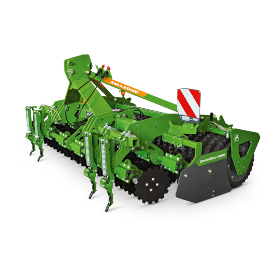
- Page 1 Original operating manual Mounted compact disc harrow CombiDisc 3000 For seedbed preparation SmartLearning www .amazone.de...
- Page 2 Please enter the identification data of the implement. The identification data can be found on the rating plate.
-
Page 3: Table Of Contents
TABLE OF CONTENTS TABLE OF CONTENTS 4.8.1 Concave discs 1 About this operating manual 4.8.2 Side guide plate Diagrams 4.8.3 Rollers 1.1.1 Warnings and signal words Universal operating tool 1.1.2 Further instructions 4.10 Lighting and identification for 1.1.3 Instructions road travel 1.1.4 Lists 4.10.1... - Page 4 TABLE OF CONTENTS 6.3.4 Preparing the wheel mark Cleaning the machine eradicator for operation 6.3.5 Adjusting the scraper to the roller 10 Loading the machine 6.3.6 Adjusting the soil guiding angle bracket 10.1 Lifting the implement Preparing the machine for road 10.2 Lashing the machine travel...
-
Page 5: About This Operating Manual
1 | About this operating manual About this operating manual CMS-T-00000081-D.1 1.1 Diagrams CMS-T-005676-C.1 1.1.1 Warnings and signal words CMS-T-00002415-A.1 Warnings are marked with a vertical bar with a triangular safety symbol and the signal word. The signal words "DANGER", "WARNING" or "CAUTION" describe the severity of the potential danger and have the following meanings: DANGER... -
Page 6: Instructions
1 | About this operating manual Diagrams ENVIRONMENTAL INFORMATION Indicates a risk for environmental damage. NOTE Indicates application tips and instructions for optimal use. 1.1.3 Instructions CMS-T-00000473-B.1 Numbered instructions CMS-T-005217-B.1 Actions that have to be performed in a specific sequence are represented as numbered instructions. The specified sequence of the actions must be observed. -
Page 7: Lists
1 | About this operating manual Diagrams Example: 1. Instruction 1 Alternative instruction 2. Instruction 2 Instructions with only one action CMS-T-005211-C.1 Instructions with only one action are not numbered, but rather shown with a arrow. Example: Instruction Instructions without sequence CMS-T-005214-C.1 Instructions that do not require a specific sequence are shown as a list with arrows. -
Page 8: Other Applicable Documents
Your suggestions for improvement help us Technische Redaktion to create ever more user-friendly operating manuals. Postfach 51 Please send us your suggestions by post, fax or D-49202 Hasbergen email. Fax: +49 (0) 5405 501-234 E-Mail: td@amazone.de MG6214-EN-II | E.1 | 17.05.2021... -
Page 9: Safety And Responsibility
2 | Safety and responsibility Safety and responsibility CMS-T-00002298-J.1 2.1 Basic safety instructions CMS-T-00002301-J.1 2.1.1 Meaning of the operating manual CMS-T-00006180-A.1 Observe the operating manual The operating manual is an important document and a part of the implement. It is intended for the user and contains safety-related information. - Page 10 2 | Safety and responsibility Basic safety instructions the machine must meet the following minimum requirements: The person is physically and mentally capable of controlling the machine. The person can safely perform work with the machine within the scope of this operating manual.
- Page 11 2 | Safety and responsibility Basic safety instructions Farmers can be e.g.: Farmers with higher education or training from a technical college Farmers by experience (e.g. inherited farm, comprehensive practical knowledge) Contractors who work by order of farmers Activity example: Safety training for agricultural helpers 2.1.2.1.4 Agricultural helpers CMS-T-00002313-A.1...
- Page 12 2 | Safety and responsibility Basic safety instructions 2.1.2.3 Danger for children CMS-T-00002308-A.1 Danger for children Children cannot assess dangerous situations and can behave unpredictably. As a result, children are at a higher risk. Keep children away. When you drive out or actuate machine movements, make sure that there are no children in the danger area.
- Page 13 2 | Safety and responsibility Basic safety instructions Observe the technical limit values Non-observance of the technical limits values of the machine can result in accidents and serious personal injury or even death. Moreover, the machine can be damaged. The technical limit values can be found in the Technical Data.
-
Page 14: Knowing And Preventing Dangers
2 | Safety and responsibility Basic safety instructions 2.1.2.4.3 Warning symbols CMS-T-00002317-B.1 Keep warning symbols legible Warning symbols on the machine warn you of risks in danger areas and are an important element of the machine's safety equipment. Missing warning symbols increase the risk of serious and lethal personal injury. - Page 15 2 | Safety and responsibility Basic safety instructions 2.1.3.2 Danger areas CMS-T-00002319-C.1 Dangers areas on the machine The following basic dangers are encountered in the danger areas: The implement and its work tools move during operation. Hydraulically raised machine parts can descend unnoticed and slowly.
-
Page 16: Safe Operation And Handling Of The Machine
2 | Safety and responsibility Basic safety instructions 2.1.4 Safe operation and handling of the machine CMS-T-00002304-G.1 2.1.4.1 Coupling implements CMS-T-00002320-C.1 Coupling the implement to the tractor Incorrectly coupling of the implement to the tractor results in hazards that can cause serious accidents. - Page 17 2 | Safety and responsibility Basic safety instructions 2.1.4.2 Driving safety CMS-T-00002321-D.1 Risk when driving on roads and fields Any mounted or towed implement as well as front or rear ballast weights on the tractor influence the driving behaviour and the steering and braking power of the tractor.
- Page 18 2 | Safety and responsibility Basic safety instructions Preparing the machine for road travel If the machine is not properly prepared for road travel, it can result in serious traffic accidents. Check the lighting and identification for road travel for proper function. Remove coarse dirt from the implement.
-
Page 19: Safe Maintenance And Modification
To ensure that the operating permit remains valid in accordance with national and international regulations, ensure that the specialist workshop only uses conversion parts, spare parts and special equipment approved by AMAZONE. MG6214-EN-II | E.1 | 17.05.2021... - Page 20 2 | Safety and responsibility Basic safety instructions 2.1.5.2 Work on the machine CMS-T-00002323-C.1 Only work on the machine when it is at a standstill If the machine is not standing still, part can move unintentionally or the machine can be set in motion.
- Page 21 2 | Safety and responsibility Basic safety instructions Maintenance work Improper maintenance work, particularly on safety-related components, endangers operational safety. This can result in accidents and serious personal injury or even death. Safety-related components include, for example, hydraulic components, electronic components, frames, springs, trailer coupling, axles and axle suspensions, lines and tanks containing flammable substances.
- Page 22 Before welding on the implement, uncouple the implement from the tractor. 2.1.5.3 Operating materials CMS-T-00002324-C.1 Unsuitable operating materials Operating materials that do not meet AMAZONE requirements can cause implement damage and accidents. Only use operating material that meet the requirements in the Technical Data.
-
Page 23: Safety Routines
CMS-T-00002325-B.1 Special equipment, accessories, and spare parts Special equipment, accessories, and spare parts that do not meet AMAZONE requirements can impede the operational safety of the implement and cause accidents. Only use original parts or parts that meet AMAZONE requirements. - Page 24 2 | Safety and responsibility Safety routines Securing the machine After uncoupling, the implement has to be secured. If the implement and implement parts are not secured, there is a risk of personal injury due to crushing and cutting. Only park the implement on stable and level ground.
- Page 25 2 | Safety and responsibility Safety routines Climbing on and off Negligent behaviour while climbing on and off can cause people to fall off the ladder. People who climb onto the machine without using the intended access steps can slip, fall, and suffer severe injury.
-
Page 26: Intended Use
Further instructions for intended use in special cases can be requested from AMAZONE. Uses other than those specified under the intended use are considered as improper. The manufacturer is not liable for any damage resulting from improper use, solely the operator is responsible. -
Page 27: Product Description
4 | Product description Product description CMS-T-00001166-E.1 4.1 Implement overview CMS-T-00001148-D.1 CMS-I-00000932 3-point mounting frame Rating plate on the implement Wheel mark eradicator Lighting and identification for road travel Disc array Track marker Side guide plate Mechanical working depth adjustment, depending on the equipment MG6214-EN-II | E.1 | 17.05.2021... -
Page 28: Function Of The Implement
4 | Product description Function of the implement CMS-I-00003754 Lighting and identification for road travel Hydraulic working depth adjustment, depending on the equipment QuickLink quick-coupling system Hose cabinet Roller scraper Threaded cartridge Trailing roller in various versions Scale for the hydraulic working depth adjustment, depending on the equipment 4.2 Function of the implement CMS-T-00005181-A.1... -
Page 29: Protective Equipment
4 | Product description Protective equipment Track marker Wheel mark eradicator Lighting and identification for road travel Trailing rollers in different versions Seed drill mounting parts 4.4 Protective equipment CMS-T-00001493-B.1 4.4.1 Track marker locking mechanism CMS-T-00001600-B.1 Both track markers must be raised for transporting the implement. -
Page 30: Warning Symbols
4 | Product description Warning symbols 4.5 Warning symbols CMS-T-00001494-D.1 4.5.1 Position of the warning symbols CMS-T-00001495-B.1 CMS-I-00000963 4.5.2 Layout of the warning symbols CMS-T-000141-D.1 Warning symbols indicate danger areas on the machine and warn against residual dangers. In these danger areas, there are permanent or unexpected dangers. -
Page 31: Description Of The Warning Symbols
4 | Product description Warning symbols 4.5.3 Description of the warning symbols CMS-T-00001497-C.1 MD 082 Risk of falling from tread surfaces and platforms Do not let anybody ride on the implement. Do not let anybody climb onto the driving implement. CMS-I-000081 MD 084 Risk of crushing for the whole body from lowering... - Page 32 4 | Product description Warning symbols MD 096 Risk of infection from escaping hydraulic fluid under high pressure Never look for leaks in hydraulic hose lines using your hand or fingers. Never attempt to plug leaks in hydraulic hose lines using your hand or fingers. If you are injured by hydraulic oil, consult a doctor immediately.
-
Page 33: Rating Plate On The Implement
4 | Product description Rating plate on the implement MD 102 Risk due to unintentional starting and rolling away of the machine Before performing any work, secure the implement against unintentional starting and rolling away. CMS-I-00002253 MD 199 Risk of accident if the hydraulic system pressure is too high Only couple the implement to tractors with a maximum tractor hydraulic pressure of 210 bar. -
Page 34: Threaded Cartridge
4 | Product description Threaded cartridge 4.7 Threaded cartridge CMS-T-00001776-B.1 The threaded cartridge contains the following items: Documents Aids CMS-I-00002306 4.8 Soil tillage tools CMS-T-00001500-E.1 4.8.1 Concave discs CMS-T-00001501-C.1 The disc array is equipped with serrated concave discs 1 . The disc gangs have an offset arrangement. -
Page 35: Side Guide Plate
4 | Product description Soil tillage tools 4.8.2 Side guide plate CMS-T-00001656-C.1 The side guide plates ensure uniform levelling of the soil surface across the whole working width. To do so, the working width and height of the side guide plates can be adjusted. - Page 36 The larger trapeze ring roller with 600 mm is suitable for heavy soils. CMS-I-00000962 4.8.3.5 Packer rollers from other manufacturers CMS-T-00005061-B.1 The AMAZONE roller product range is supplemented with rollers from suppliers. Packer rollers from Working width 3 m Working width 4 m...
-
Page 37: Universal Operating Tool
4 | Product description Universal operating tool 4.9 Universal operating tool CMS-T-00001735-B.1 Setting work on the implement is performed with the universal operating tool 1 . The universal operating tool is parked in a holder on the implement frame. CMS-I-00001082 4.10 Lighting and identification for road travel CMS-T-00006398-A.1 4.10.1 Lighting and identification to the rear... -
Page 38: Lighting And Identification To The Front
4 | Product description QuickLink quick-coupling system 4.10.2 Lighting and identification to the front CMS-T-00006393-A.1 Warning signs Reflector, white Side marker lights CMS-I-00002940 NOTE The lighting and identification for road travel can vary depending on the national regulations. 4.11 QuickLink quick-coupling system CMS-T-00001659-B.1 Using the quick-coupling system, the soil tillage implement can be combined with a pack top seed... -
Page 39: Technical Data
5 | Technical data Technical data CMS-T-00003163-D.1 5.1 Dimensions CMS-T-00003165-B.1 Dimensions CombiDisc 3000 [mm] Transport width 3000 Transport height 1560 Total length 1870 Working width 3000 Centre of gravity distance 1100 5.2 Permissible total weight CMS-T-00003167-B.1 CombiDisc 3000 4180 kg 5.3 Soil tillage tool... -
Page 40: Mounting Category
5 | Technical data Mounting category 5.4 Mounting category CMS-T-00003170-B.1 Type Category 3 top link CombiDisc 3000 as a solo implement Category 2 or Category 3 lower link CombiDisc 3000 as a seeding combination Category 3 5.5 QuickLink quick-coupling system CMS-T-00003190-C.1... -
Page 41: Noise Development Data
5 | Technical data Noise development data Hydraulic system Maximum operating pressure 210 bar Tractor pump output At least 15 l/min at 150 bar HLP68 DIN51524 Implement hydraulic oil The hydraulic oil is suitable for the combined hydraulic oil circuits of all standard tractors. Control units Depending on the implement equipment 5.8 Noise development data... -
Page 42: Preparing The Machine
6 | Preparing the machine Preparing the machine CMS-T-00001472-D.1 6.1 Calculating the required tractor characteristics CMS-T-00000063-B.1 CMS-I-00000581 Calculated Designation Unit Description values Tractor empty weight Front axle load of the operational tractor without mounted implement or ballast weights Rear axle load of the operational tractor without mounted implement or ballast weights Total weight of front-mounted implement or front ballast Permissible total weight of rear-mounted implement or rear... - Page 43 6 | Preparing the machine Calculating the required tractor characteristics Calculated Designation Unit Description values Distance between the centre of the front axle and the centre of the lower link connection Centre of gravity distance: Distance between the centre of gravity of the front-mounted implement or the front ballast and the centre of the lower link connection Wheelbase...
- Page 44 6 | Preparing the machine Calculating the required tractor characteristics 3. Calculate the actual total weight of the tractor- implement combination. CMS-I-00000515 4. Calculate the actual rear axle load. Htat Vtat Htat Htat CMS-I-00000514 5. Determine the tyre load capacity for two tractor tyres in the manufacturer specifications.
-
Page 45: Coupling The Implement
6 | Preparing the machine Coupling the implement 6.2 Coupling the implement CMS-T-00003183-C.1 6.2.1 Preparing the 3-point mounting frame CMS-T-00003187-B.1 6.2.1.1 Attach the ball sleeves for mounting category 2 CMS-T-00003188-B.1 Mounting category 2 Diameter measurements 25 mm 28 mm 1. Select the top link pin 1 and lower link step pin 2 for mounting category 2. - Page 46 6 | Preparing the machine Coupling the implement 6.2.1.2 Attach the ball sleeves for mounting category 3 CMS-T-00003189-B.1 Mounting category 3 Diameter measurements 31.7 mm 36.6 mm 1. Install the top link pin 1 and lower link step pin 2 of mounting category 3. CMS-I-00001817 2.
-
Page 47: Coupling The 3-Point Mounting Frame
6 | Preparing the machine Coupling the implement 6.2.1.3 Mounting the 3-point mounting frame extension CMS-T-00001564-A.1 The extension of the 3-point mounting frame 1 serves to enlarge the distance from the tractor to the implement. 1. The 3-point mounting frame extension consists of 3 spacer elements. -
Page 48: Coupling The Hydraulic Hose Lines
6 | Preparing the machine Coupling the implement 6.2.3 Coupling the hydraulic hose lines CMS-T-00006275-A.1 All hydraulic hoses are equipped with handles. The handles have colour labels with a code number or a code letter. The labels are assigned to the respective hydraulic functions of the pressure line of a tractor control unit. -
Page 49: Coupling The Power Supply
6 | Preparing the machine Coupling the implement IMPORTANT Implement damage due to insufficient hydraulic oil return flow Only use DN16 lines for the pressureless hydraulic oil return flow. Select short return paths. Connect the pressureless hydraulic return flow correctly. Install the supplied coupling sleeve on the pressureless hydraulic oil return. -
Page 50: Preparing The Implement For Operation
6 | Preparing the machine Preparing the implement for operation 6.3 Preparing the implement for operation CMS-T-00003184-C.1 6.3.1 Adjusting the working depth CMS-T-00001475-C.1 6.3.1.1 Manually adjusting the working depth of the concave discs CMS-T-00001727-B.1 6.3.1.1.1 Increase the working depth of the concave discs manually CMS-T-00001554-B.1 1. - Page 51 6 | Preparing the machine Preparing the implement for operation 6.3.1.1.2 Reduce the working depth of the concave discs manually CMS-T-00001728-B.1 1. Raise the implement. The front spacer elements 1 are relieved. To reduce the working depth, swivel out the desired number of spacer elements in front of the stop washer 2 .
- Page 52 6 | Preparing the machine Preparing the implement for operation NOTE Selection of the working depth depends on different factors, e.g.: Soil type: light to heavy, dry to wet Forward speed Setting Condition of the seedbed 6.3.1.3 Adjust the working depth of individual concave discs manually CMS-T-00001480-B.1 CAUTION Crushing hazard for hands...
-
Page 53: Preparing The Side Guide Plates For Operation
6 | Preparing the machine Preparing the implement for operation 6.3.1.4 Adjust the working depth of the side guide plates CMS-T-00001483-B.1 1. Remove the nuts and washers 5 . To adjust the working depth of the side guide plates install the side guide plates in the hole pattern 4 in the desired position. -
Page 54: Preparing The Track Marker For Operation
6 | Preparing the machine Preparing the implement for operation 6.3.3 Preparing the track marker for operation CMS-T-00001725-D.1 6.3.3.1 Unfolding the track markers CMS-T-00001561-C.1 The hydraulically actuated track markers produce alternating marks. This mark serves as an reference to the tractor driver for driving the next bout after turning at the headland. - Page 55 6 | Preparing the machine Preparing the implement for operation 6.3.3.2 Determining the track marker length CMS-T-00004725-B.1 Working width of the Distance A [m] implement [m] Read the distance A from the centre of the implement to the track marker disc from the table. CMS-I-00003078 6.3.3.3 Adjusting the track marker length CMS-T-00001487-C.1...
-
Page 56: Preparing The Wheel Mark Eradicator For Operation
6 | Preparing the machine Preparing the implement for operation 6.3.3.4 Adjusting the track marker intensity CMS-T-00001726-C.1 1. loosen the bolts 1 with the universal operating tool. Work application Pitch Reduce - Light soils About parallel to the direction of travel Increase + Heavy soils More on-grip to the direction of... - Page 57 6 | Preparing the machine Preparing the implement for operation 1. Raise the implement. 2. Release the linch pin 2 . 3. Hold the wheel mark eradicator by the recessed grip 1 . 4. Remove the locking pin 3 . The maximum working depth is 150 mm.
-
Page 58: Adjusting The Scraper To The Roller
6 | Preparing the machine Preparing the implement for operation Wheel mark eradicator Number Operating conditions Pulling force requirement coulter Shallow loosening and levelling of High pulling force Wing coulter medium, silty soils requirement Medium pulling force Heart-shaped coulter Medium-depth loosening of various soils requirement Low pulling force Narrow coulter... -
Page 59: Adjusting The Soil Guiding Angle Bracket
6 | Preparing the machine Preparing the machine for road travel NOTE Permitted distances between the roller element and scraper: Wedge ring roller: 10 mm to 15 mm Tooth packer roller and trapeze ring roller: 0.5 mm to 4 mm 6.3.6 Adjusting the soil guiding angle bracket CMS-T-00005249-A.1 1. -
Page 60: Preparing The Track Markers For Road Travel
6 | Preparing the machine Calculating the permissible payload 1. Raise the implement. 2. Remove the linch pin 2 . 3. Pull out the pin 3 . To maintain the transport width, move the side guide plates 1 to the desired position. - Page 61 6 | Preparing the machine Calculating the permissible payload Maximum payload = Permissible technical implement weight - tare weight 1. Read the permissible technical implement weight from the rating plate. To determine the tare weight, weigh the implement with empty hoppers. 3.
-
Page 62: Using The Machine
7 | Using the machine Using the machine CMS-T-00001492-A.1 7.1 Using the implement CMS-T-00001531-A.1 During field operation as a solo implement, operations are limited to lifting and lowering the implement at the headlands. 1. Align the implement parallel to the ground. 2. -
Page 63: Parking The Machine
8 | Parking the machine Parking the machine CMS-T-00001609-D.1 8.1 Moving the wheel mark eradicator into parking position CMS-T-00001616-B.1 IMPORTANT Damage to the wheel mark eradicators due to the implement weight When you park the implement, put the wheel mark eradicators into parking position. -
Page 64: Uncoupling The 3-Point Mounting Frame
8 | Parking the machine Uncoupling the 3-point mounting frame 8.2 Uncoupling the 3-point mounting frame CMS-T-00001401-C.1 1. Park the implement on a level surface with solid ground. 2. Release the top link 1 . 3. Uncouple the top link 1 from the implement. 4. -
Page 65: Uncoupling The Power Supply
8 | Parking the machine Uncoupling the power supply 8.4 Uncoupling the power supply CMS-T-00001402-D.1 1. Pull out the plug 1 for the power supply. CMS-I-00001048 2. Hang the plugs 1 in the hose cabinet. CMS-I-00001248 MG6214-EN-II | E.1 | 17.05.2021... -
Page 66: Repairing The Machine
9 | Repairing the machine Repairing the machine CMS-T-00001529-E.1 9.1 Maintaining the machine CMS-T-00003174-C.1 9.1.1 Maintenance schedule After initial operation Checking the hydraulic hose lines see page 63 Checking the concave disc carrier connection see page 64 Checking the roller see page 66 as required Replacing the discs... -
Page 67: Checking The Top Link Pin And Lower Link Pin
9 | Repairing the machine Maintaining the machine 9.1.2 Checking the top link pin and lower link pin CMS-T-00002330-C.1 INTERVAL daily 1. Check the top link pins and lower link pins for cracks or broken areas. 2. Replace the pins if there is significant wear. 9.1.3 Checking the hydraulic hose lines CMS-T-00002331-B.1 INTERVAL... -
Page 68: Replacing The Discs
9 | Repairing the machine Maintaining the machine 9.1.4 Replacing the discs CMS-T-00002327-C.1 INTERVAL as required REQUIREMENTS The wear limit specified in the technical data has been reached. 1. Slightly raise the implement. 2. Loosen the 4 bolts 1 for the disc fastening. 3. -
Page 69: Checking The Wheel Mark Eradicator Coulter
9 | Repairing the machine Maintaining the machine 9.1.6 Checking the wheel mark eradicator coulter CMS-T-00002497-C.1 INTERVAL Every 50 operating hours Every 3 months IMPORTANT The tool carriers become worn when constantly working in the soil. When the wear limit of the wheel mark eradicator coulter has been exceeded, the tool carriers constantly work in the soil horizon. -
Page 70: Checking The Roller
9 | Repairing the machine Maintaining the machine 9.1.7 Checking the roller CMS-T-00003191-B.1 INTERVAL After initial operation Every 200 operating hours Every 3 months 1. Check the alignment of the bolted connection 1 . 2. Check the bolts for tightness. To check the bearings of the roller for ease of movement, turn the roller 2 by hand. -
Page 71: Lubricating The Machine
9 | Repairing the machine Lubricating the machine 9.2 Lubricating the machine CMS-T-00003175-B.1 IMPORTANT Implement damage due to improper lubrication Grease the implement at the marked lubrication points according to the lubrication schedule. To ensure that dirt is not pressed into the lubrication points, thoroughly clean the grease nipples and the grease gun. -
Page 72: Overview Of Lubrication Points
9 | Repairing the machine Lubricating the machine 9.2.1 Overview of lubrication points CMS-T-00003176-B.1 CMS-I-00002452 Every 50 operating hours CMS-I-00002080 MG6214-EN-II | E.1 | 17.05.2021... -
Page 73: Eliminating Faults
9 | Repairing the machine Eliminating faults 9.3 Eliminating faults CMS-T-00003178-B.1 Errors Cause Solution The packer roller turns stiffly. If the tooth packer roller rotates pull the roller over firm ground. stiffly during initial operation, e.g. due to areas glued by paint, The track marker collision The track marker has encountered see page 70... -
Page 74: Cleaning The Machine
9 | Repairing the machine Cleaning the machine 9.3.1 The track marker collision protection is triggered. CMS-T-00002345-B.1 The track marker has encountered a solid obstacle. The shear bolt is torn and the track marker folded to the rear. NOTE Only use original bolts as a replacement. Refer to the online spare parts list. -
Page 75: Loading The Machine
10 | Loading the machine Loading the machine CMS-T-00001527-D.1 10.1 Lifting the implement CMS-T-00001528-D.1 CMS-I-00001012 The implement has 4 lashing points for slings for lifting. MG6214-EN-II | E.1 | 17.05.2021... -
Page 76: Lashing The Machine
10 | Loading the machine Lashing the machine WARNING Risk of accidents due to improperly attached slings for lifting If the slings are not attached at the marked lashing points, the implement can be damaged during lifting and endanger safety. Only attach the slings for lifting at the marked lashing points. - Page 77 10 | Loading the machine Lashing the machine WARNING Risk of accidents due to improperly attached lashing straps If the lashing straps are not attached at the marked lashing points, the implement can be damaged during lashing and endanger safety. Attach the lashing straps only at the marked lashing points.
-
Page 78: Appendix
11 | Appendix Appendix CMS-T-00001468-C.1 11.1 Bolt tightening torques CMS-T-00000373-B.1 CMS-I-000260 NOTE Unless specified otherwise, the bolt tightening torques listed in the table apply. 10.9 12.9 M8x1 16(17) M10x1 18(19) M12x1.5 M 14x1.5 M16x1.5 M18x1.5 M20x1.5 MG6214-EN-II | E.1 | 17.05.2021... -
Page 79: Other Applicable Documents
11 | Appendix Other applicable documents 10.9 12.9 M22x1.5 1050 1000 1200 M24x2 1100 1300 1050 1500 1800 M27x2 1150 1600 1950 1450 2000 2400 M30x2 1600 2250 2700 CMS-I-00000065 20.4 40.7 70.5 11.2 Other applicable documents CMS-T-00001469-A.1 Tractor operating manual Operating manual for the Cataya 3000 Special/ Super Operating manual for the Centaya 3000 Super... -
Page 80: Directories
12 | Directories Directories 12.1 Glossary CMS-T-00000513-B.1 Machine Mounted implements are accessory parts of the tractor. However, mounted implements are always referred to as the implement in this operating manual. Operating materials Operating materials serve to ensure operational readiness. Operating materials include e.g. cleaning agents and lubricants such as lubricating oil, greases or cleaners. -
Page 81: Index
12 | Directories Index 12.2 Index Contact data Technical editing 3-point mounting frame coupling Extension, installation of Dimensions uncoupling Discs 3-point mounting frame extension replacing mounting Documents Drivable slope inclination Address Technical editing Adjusting the soil guiding angle bracket Eliminating faults Adjust the working depth of the concave discs hydraulically Headlands... - Page 82 12 | Directories Index Preparing the track marker for operation Adjusting the track marker intensity Adjusting the track marker length Lighting and identification Determining the track marker length Front Unfolding the track markers Rear Preparing the wheel mark eradicator for operation Loading Adjusting the track width of the wheel mark Lubricants...
- Page 83 12 | Directories Index Rollers Side guide plate Technical data Dimensions Drivable slope inclination Lubricants Mounting category Noise development data Performance characteristics of the tractor QuickLink quick-coupling system Soil tillage tool Working speed Threaded cartridge Three-point hitch coupling Track marker locking mechanism Product description Unloading Warning symbols...
- Page 86 AMAZONEN-WERKE H. DREYER SE & Co. KG Postfach 51 49202 Hasbergen-Gaste Germany +49 (0) 5405 501-0 amazone@amazone.de www.amazone.de MG6214-EN-II | E.1 | 17.05.2021...
Need help?
Do you have a question about the CombiDisc 3000 and is the answer not in the manual?
Questions and answers