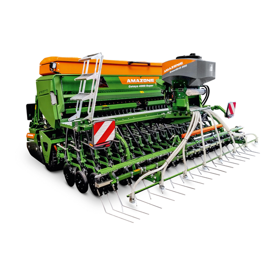
Amazone Cataya 3000 Super Original Operating Manual
Mechanical pack top seed drill
Hide thumbs
Also See for Cataya 3000 Super:
- Operating manual (223 pages) ,
- Operating manual (252 pages) ,
- Operating manual (168 pages)

Subscribe to Our Youtube Channel
Related Manuals for Amazone Cataya 3000 Super


Summary of Contents for Amazone Cataya 3000 Super
- Page 1 Original operating manual Mechanical pack top seed drill Cataya 3000/4000 Super SmartLearning www.amazone.de...
- Page 2 Please enter the identification data of the implement. The identification data can be found on the rating plate.
-
Page 3: Table Of Contents
Permissible mounting categories Protective devices Noise emission data 4.4.1 Grating screen Drivable slope inclination 4.4.2 Chain drive cover 4.4.3 Metering unit cover 4.4.4 Road safety bars Warning symbols 4.5.1 Positions of the warning symbols MG7371-US-EN-US | A.1 | 24.01.2023 | © AMAZONE... - Page 4 Folding the tramline marker on the 10.2.2 Checking the TwinTeC cutting disk exact following harrow spacing 6.4.3 Bringing the exact following harrow 10.2.3 Checking the TwinTeC cutting disks or seed harrow into transport position 106 MG7371-US-EN-US | A.1 | 24.01.2023 | © AMAZONE...
- Page 5 Lubricating the drive chain on the right metering drive 11 Loading the implement 11.1 Lifting the implement 11.2 Lashing the implement 12 Appendix 12.1 Bolt tightening torques 12.2 Other applicable documents 13 Directories 13.1 Glossary 13.2 Index MG7371-US-EN-US | A.1 | 24.01.2023 | © AMAZONE...
-
Page 7: About This Operating Manual
WARNING Indicates a possible danger with moderate risk of severe or fatal physical injury. CAUTION Indicates a danger with low risk of minor or moderate physical injury. MG7371-US-EN-US | A.1 | 24.01.2023 | © AMAZONE... -
Page 8: Additional Instructions
CMS-T-005678-B.1 Responses to instructions are indicated by an arrow. Example: 1. Instruction 1 Response to instruction 1 2. Instruction 2 1.2.3.2 Alternative instructions CMS-T-00000110-B.1 Alternative instructions are introduced with the word "or". MG7371-US-EN-US | A.1 | 24.01.2023 | © AMAZONE... -
Page 9: Listings
Example: Point 1 Point 2 1.2.5 Item numbers in illustrations CMS-T-000023-B.1 A framed number in the text, e.g. a 1 , indicates an item number in an adjacent figure. MG7371-US-EN-US | A.1 | 24.01.2023 | © AMAZONE... -
Page 10: Direction Information
Your suggestions for improvement help us Technische Redaktion provide increasingly user-friendly operating manuals. Postfach 51 Please send us your suggestions by post, fax or D-49202 Hasbergen email. Fax: +49 (0) 5405 501-234 E-Mail: td@amazone.de CMS-I-00000638 MG7371-US-EN-US | A.1 | 24.01.2023 | © AMAZONE... -
Page 11: Safety And Responsibility
2.1.2.1.1 Requirements imposed on all persons who work with the implement CMS-T-00011160-A.1 If the implement is used improperly, people can be injured or killed. To prevent accidents due to improper use, every person who works with MG7371-US-EN-US | A.1 | 24.01.2023 | © AMAZONE... - Page 12 Farmers are categorically familiar with work involving agricultural machines and can instruct agricultural helpers in how to use the machines, if necessary. They can perform specific, simple repairs and maintenance tasks on agricultural machines themselves. MG7371-US-EN-US | A.1 | 24.01.2023 | © AMAZONE...
- Page 13 Objects thrown upward by the tractor or implement can hit and injure persons accompanying the driver. Never allow persons to ride on the implement. Never allow people to climb onto the moving implement. MG7371-US-EN-US | A.1 | 24.01.2023 | © AMAZONE...
- Page 14 Failure to comply with the technical limits values of the implement can cause accidents and serious personal injury or death. Moreover, the implement can be damaged. The technical limit values are provided in the Technical data. Comply with the technical limit values. MG7371-US-EN-US | A.1 | 24.01.2023 | © AMAZONE...
- Page 15 Missing warning symbols increase the risk of serious or fatal injury. Clean dirty warning symbols. Immediately replace any damaged or illegible warning symbols. Affix the intended warning symbols on spare parts. MG7371-US-EN-US | A.1 | 24.01.2023 | © AMAZONE...
-
Page 16: Recognizing And Avoiding Dangers
If people enter the danger area, immediately switch off engines and drives. Before working in the danger area of the implement, secure the tractor and implement. This also applies for quick inspection tasks. MG7371-US-EN-US | A.1 | 24.01.2023 | © AMAZONE... - Page 17 Only couple and transport the implement with suitable tractors. When the implement is coupled on the tractor, ensure that the tractor's connecting device meets the implement requirements. Carefully couple the implement to the tractor. MG7371-US-EN-US | A.1 | 24.01.2023 | © AMAZONE...
- Page 18 If the implement is not properly prepared for road travel, it can cause serious traffic accidents. Check the lighting and identification for road travel for proper function. Remove coarse contaminants from the implement. Follow the instructions in the section "Preparing the implement for road travel". MG7371-US-EN-US | A.1 | 24.01.2023 | © AMAZONE...
-
Page 19: Safe Maintenance And Modification
This ensures that the operating permit remains valid in accordance with national and international regulations. Ensure that the specialist workshop only uses conversion parts, spare parts, and special equipment approved by AMAZONE. MG7371-US-EN-US | A.1 | 24.01.2023 | © AMAZONE... - Page 20 Remove the key from the battery circuit breaker. Wait until all parts still in motion after the unit is switched off have come to a stop and until hot parts have cooled down. MG7371-US-EN-US | A.1 | 24.01.2023 | © AMAZONE...
- Page 21 Never position yourself under raised implement parts. If you must perform tasks on or under raised implement parts, lower the implement parts or secure the raised implement parts with a mechanical support or hydraulic locking device. MG7371-US-EN-US | A.1 | 24.01.2023 | © AMAZONE...
- Page 22 CMS-T-00011149-A.1 Special equipment, accessories, and spare parts Special equipment, accessories, and spare parts that do not meet AMAZONE requirements can impair the operational reliability of the implement and cause accidents. Only use original parts or parts that meet the AMAZONE requirements.
-
Page 23: Safety Routines
If there is doubt as to whether the protective devices are properly installed and functional, have the protective devices checked by a qualified specialist workshop. Ensure that the protective devices are properly installed and functional before any activity on the implement. Replace damaged protective devices. MG7371-US-EN-US | A.1 | 24.01.2023 | © AMAZONE... - Page 24 When climbing up and down, never use the control elements as a hand grip. Accidental activation of control elements can unintentionally trigger potentially dangerous functions. When climbing down, never jump off of the implement. MG7371-US-EN-US | A.1 | 24.01.2023 | © AMAZONE...
-
Page 25: Intended Use
Uses other than those specified under the intended use are considered non-intended use. The manufacturer is not liable for any damage resulting from non-intended use; the owner is exclusively liable for such damage. MG7371-US-EN-US | A.1 | 24.01.2023 | © AMAZONE... -
Page 26: Product Description
Product description CMS-T-00012475-A.1 4.1 Implement overview CMS-T-00007914-A.1 CMS-I-00005518 Hopper Radar sensor Tramline marker Roller harrow, or exact following harrow TwinTeC double-disk coulters, or RoTec single- Loading board disk coulters Metering unit Track marker MG7371-US-EN-US | A.1 | 24.01.2023 | © AMAZONE... -
Page 27: Function Of The Implement
4 | Product description Function of the implement CMS-I-00005519 Cabinet for supply lines SmartCenter 4.2 Function of the implement CMS-T-00007918-A.1 CMS-I-00005498 MG7371-US-EN-US | A.1 | 24.01.2023 | © AMAZONE... -
Page 28: Special Equipment
Connection unit for tramline marker without track marker Seed metering wheel for peas and beans Mechanical coulter pressure indicator Harrow set on the TwinTeC coulter Exact following harrow Mounting kit for exact following harrow MG7371-US-EN-US | A.1 | 24.01.2023 | © AMAZONE... -
Page 29: Protective Devices
Preparation loading dimension 8.04 ft (2.45 m) 4.4 Protective devices CMS-T-00007927-A.1 4.4.1 Grating screen CMS-T-00007928-A.1 The grating screen 1 in the hopper prevents contact with the running agitator shaft. CMS-I-00005523 MG7371-US-EN-US | A.1 | 24.01.2023 | © AMAZONE... -
Page 30: Chain Drive Cover
CMS-I-00005526 4.4.4 Road safety bars CMS-T-00007937-C.1 The road safety bars 1 cover the tines of the exact following harrow or seed harrow during road travel to protect against injury or damage. CMS-I-00005527 MG7371-US-EN-US | A.1 | 24.01.2023 | © AMAZONE... -
Page 31: Warning Symbols
4 | Product description Warning symbols 4.5 Warning symbols CMS-T-00012476-A.1 4.5.1 Positions of the warning symbols CMS-T-00012478-A.1 CMS-I-00005544 CMS-I-00005551 MG7371-US-EN-US | A.1 | 24.01.2023 | © AMAZONE... - Page 32 4 | Product description Warning symbols CMS-I-00005552 CMS-I-00005550 MG7371-US-EN-US | A.1 | 24.01.2023 | © AMAZONE...
-
Page 33: Structure Of The Warning Symbols
Ensure that no one is in the danger area. MD082 Risk of falling from stepping surfaces and platforms Never allow people to ride on the implement. Never allow people to climb onto the moving implement. CMS-I-000081 MG7371-US-EN-US | A.1 | 24.01.2023 | © AMAZONE... - Page 34 Never search for leaks in hydraulic hose lines using your hand or fingers. Never attempt to seal leaks in hydraulic hose lines using your hand or fingers. If you are injured by hydraulic oil, seek medical attention immediately. CMS-I-000216 MG7371-US-EN-US | A.1 | 24.01.2023 | © AMAZONE...
- Page 35 CMS-I-00000486 MD154 Risk of severe or fatal injury due to seeding harrow tines without safeguard Before driving on public roads, attach the road safety bar as described in the operating manual. CMS-I-00003657 MG7371-US-EN-US | A.1 | 24.01.2023 | © AMAZONE...
- Page 36 Wait until moving parts have come to a standstill before reaching into the danger area. CMS-I-00003694 Ensure that no one is standing in the danger area or in the vicinity of moving parts. MG7371-US-EN-US | A.1 | 24.01.2023 | © AMAZONE...
-
Page 37: Rating Plate On The Implement
Ensure that no one is standing in the danger area or in the vicinity of moving parts. 4.6 Rating plate on the implement CMS-T-00004505-G.1 Implement number Vehicle ID number Product Permissible technical implement weight Model year Year of manufacture CMS-I-00004294 MG7371-US-EN-US | A.1 | 24.01.2023 | © AMAZONE... -
Page 38: Gewindepack
The hand wash tank has a water tap 1 and a soap dispenser 2 . The hand wash tank has a capacity of 1.32 gal (5 l) and it has a screw cap 3 . CMS-I-00005533 MG7371-US-EN-US | A.1 | 24.01.2023 | © AMAZONE... -
Page 39: Metering System
4.10 Universal operating tool CMS-T-00001735-C.1 Use the universal operating tool to perform adjustment tasks on the implement 1 . The universal operating tool is parked in a holder on the implement frame. CMS-I-00001082 MG7371-US-EN-US | A.1 | 24.01.2023 | © AMAZONE... -
Page 40: Camera System
4.12 Radar sensor CMS-T-00001778-C.1 For electric drives, the radar sensor detects the working speed. The working speed is used to determine the worked area and the rotational speed required for the metering drives. CMS-I-00002221 MG7371-US-EN-US | A.1 | 24.01.2023 | © AMAZONE... -
Page 41: Lighting
The coulter array lighting 1 enables better visibility of the seeding coulters in the dark. The coulter array lighting is switched together with the work floodlights via the control terminal or control computer. CMS-I-00005664 MG7371-US-EN-US | A.1 | 24.01.2023 | © AMAZONE... -
Page 42: Mounting Frame
The depth control disks and depth control wheel 1 limit the placement depth and clean the cutting disks. Coulter pressure and placement depth can be adjusted. For soil tillage without seeding, the coulters can be lifted-out. CMS-I-00004578 MG7371-US-EN-US | A.1 | 24.01.2023 | © AMAZONE... -
Page 43: Twintec Coulter
Coulter pressure and placement depth can be adjusted. For soil tillage without seeding, the coulters can be lifted. CMS-I-00003166 MG7371-US-EN-US | A.1 | 24.01.2023 | © AMAZONE... -
Page 44: Exact Following Harrow
4.18 Coulter harrow CMS-T-00006648-C.1 The harrow tines 1 of the coulter harrow uniformly cover the deposited metered material with loose soil. The pitch and the height of the harrow tines can be adjusted. CMS-I-00004734 MG7371-US-EN-US | A.1 | 24.01.2023 | © AMAZONE... -
Page 45: Roller Harrow
Depending on the implement equipment, a different number of disks can be installed on the implement. The track width and the pitch of the track disks can be adjusted. CMS-I-00003167 MG7371-US-EN-US | A.1 | 24.01.2023 | © AMAZONE... -
Page 46: Track Markers
CMS-I-00005540 4.22 GreenDrill CMS-T-00005046-B.1 The GreenDrill pack top seed drill enables seeding of fine seed and catch crops while tilling the soil or seeding of nurse crops while sowing. CMS-I-00003609 MG7371-US-EN-US | A.1 | 24.01.2023 | © AMAZONE... -
Page 47: Technical Data
Working speed (dependent on the soil tillage Seeding coulter implement) TwinTec coulter 4.97 mph (8 km/h) to 7.46 mph (12 km/h) RoTeC coulter 3.73 mph (6 km/h) to 7.46 mph (12 km/h) MG7371-US-EN-US | A.1 | 24.01.2023 | © AMAZONE... -
Page 48: Soil Tillage Tools
The emission sound pressure level primarily depends on the vehicle used. 5.8 Drivable slope inclination CMS-T-00004990-A.1 Across the slope In direction of travel left In direction of travel right Uphill and downhill Uphill Downhill MG7371-US-EN-US | A.1 | 24.01.2023 | © AMAZONE... -
Page 49: Capacity Characteristics Of The Tractor
At least 2.64 gpm (10 l/min) at 2,175.57 psi (150 bar) HLP68 DIN 51524 Implement hydraulic oil The hydraulic oil is suitable for the combined hydraulic oil circuits of all standard tractor manufacturers. Control units Depending on the implement equipment MG7371-US-EN-US | A.1 | 24.01.2023 | © AMAZONE... -
Page 50: Preparing The Implement
Permissible total weight of rear-mounted implement or rear lb ( kg) ballast Distance between the center of gravity of the front-mounted ft ( m) implement or the front ballast and the center of the front axle MG7371-US-EN-US | A.1 | 24.01.2023 | © AMAZONE... - Page 51 T b 0,2 T b Vmin Vmin Vmin CMS-I-00000513 2. Calculate the actual front axle load. × × - × G a b T b G c + d Vtat Vtat Vtat CMS-I-00000516 MG7371-US-EN-US | A.1 | 24.01.2023 | © AMAZONE...
- Page 52 ( kg) lb ( kg) ≤ ≤ Front axle load lb ( kg) lb ( kg) lb ( kg) ≤ ≤ Rear axle load lb ( kg) lb ( kg) lb ( kg) MG7371-US-EN-US | A.1 | 24.01.2023 | © AMAZONE...
-
Page 53: Coupling The Implement
The tractor control unit is used in different activation types, depending on the hydraulic function: CMS-I-00000121 Activation type Function Symbol Latching Permanent oil circulation Oil circulation until action is Momentary executed Free oil flow in the tractor control Floating unit MG7371-US-EN-US | A.1 | 24.01.2023 | © AMAZONE... - Page 54 Only use DN16 lines for the pressureless hydraulic oil return flow. Select short return paths. Connect the pressureless hydraulic return flow correctly. Mount the supplied coupling sleeve on the pressureless hydraulic oil return. MG7371-US-EN-US | A.1 | 24.01.2023 | © AMAZONE...
-
Page 55: Coupling The Power Supply
1 or into an extension cable 2 at the rear of the tractor. 2. Route the camera system cable with sufficient freedom of movement and without chafing or pinching points. CMS-I-00007453 MG7371-US-EN-US | A.1 | 24.01.2023 | © AMAZONE... -
Page 56: Coupling The 3-Point Mounting Frame
2. Dismount the lock bracket 3 . 3. Slowly lift the soil tillage implement. The pack top seed drill 1 rests in the catching sockets 2 of the soil tillage implement. CMS-I-00003590 MG7371-US-EN-US | A.1 | 24.01.2023 | © AMAZONE... - Page 57 9. Adjust the top link to the desired length. 10. Lift the soil tillage implement with the coupled seed drill. 11. Take the parking supports 1 out of the implement 2 on both sides. CMS-I-00004938 MG7371-US-EN-US | A.1 | 24.01.2023 | © AMAZONE...
- Page 58 1 . CMS-I-00003485 14. Connect the supply line 2 for the rear lighting and identification to the soil tillage implement 1 . CMS-I-00004527 MG7371-US-EN-US | A.1 | 24.01.2023 | © AMAZONE...
-
Page 59: Preparing The Implement For Use
CMS-I-00002608 completely lift and lower the implement. To configure the working position sensor, see the ISOBUS software operating manual, "Configuring the working position sensor" see operating manual "control computer". MG7371-US-EN-US | A.1 | 24.01.2023 | © AMAZONE... -
Page 60: Operating The Hopper Cover
For lower spread rates, the fill level sensor must be attached in the lower area of the hopper. For higher spread rates, the fill level sensor must be attached in the upper area of the hopper. MG7371-US-EN-US | A.1 | 24.01.2023 | © AMAZONE... - Page 61 The fill level sensor can be adjusted vertically. 6. Tighten the wing nut. NOTE When the fill level sensor is no longer covered, a warning message appears on the control terminal or control computer. CMS-I-00005568 MG7371-US-EN-US | A.1 | 24.01.2023 | © AMAZONE...
-
Page 62: Attaching The Seed Guide Elements
1. Open the hopper cover. 2. Release the locking mechanism 1 with the universal operating tool 2 . CMS-I-00005769 3. Slide the lock plate 1 to the side. The grating screens can be opened. CMS-I-00005771 MG7371-US-EN-US | A.1 | 24.01.2023 | © AMAZONE... -
Page 63: Filling The Hopper
7. Close hopper cover. CMS-I-00006247 6.3.5 Filling the hopper CMS-T-00008053-A.1 1. Lower the implement. 2. Open the hopper cover. 3. Fill the hopper via the grating screen 1 . 4. Close hopper cover. CMS-I-00005572 MG7371-US-EN-US | A.1 | 24.01.2023 | © AMAZONE... -
Page 64: Adjusting The Placement Depth On The Twintec Coulter
The optimal adjustment can only be determined in field operation. The greatest placement depth is achieved by removing the depth control disks or depth control wheels. CMS-I-00004587 MG7371-US-EN-US | A.1 | 24.01.2023 | © AMAZONE... -
Page 65: Manual Coulter Pressure Adjustment
2. Fit the universal operating tool on the adjustment spindle 1 . NOTE Adjustment of the coulter pressure must be adapted to the respective operating conditions. The optimal adjustment can only be determined in field operation. CMS-I-00004579 MG7371-US-EN-US | A.1 | 24.01.2023 | © AMAZONE... - Page 66 The actual coulter pressure is shown on the mechanical coulter pressure indicator on the front side of the implement. NOTE The scale value is only for orientation. The scale value does not correspond to a specific measurement. CMS-I-00005586 MG7371-US-EN-US | A.1 | 24.01.2023 | © AMAZONE...
- Page 67 "green 1" To reduce the coulter pressure: Activate the tractor control unit "green 2". To check the adjustment: Sow 98.43 ft (30 m) at working speed and check the work pattern. MG7371-US-EN-US | A.1 | 24.01.2023 | © AMAZONE...
-
Page 68: Adjusting The Coulter Harrow
To bring the harrow tines into the steep working position: Mount the pin 4 in hole 2 . To check the adjustment: Sow 98.43 ft (30 m) at working speed and check the work pattern. MG7371-US-EN-US | A.1 | 24.01.2023 | © AMAZONE... - Page 69 The optimal adjustment can only be determined in field operation. 3. Bring the harrow holder 2 into the desired position. CMS-I-00003182 4. Mount the bolt 3 . MG7371-US-EN-US | A.1 | 24.01.2023 | © AMAZONE...
-
Page 70: Adjusting The Exact Following Harrow
3. Tighten the bolt 2 with the universal operating tool. 4. Make the same adjustment on the other side of the implement. To check the adjustment: Sow 98.43 ft (30 m) at working speed and check the work pattern. CMS-I-00004674 MG7371-US-EN-US | A.1 | 24.01.2023 | © AMAZONE... - Page 71 The exact following harrow pressure must be adjusted such that all seed rows are uniformly covered with soil. For heavy soils, the pressure must be higher than it is for light soils. MG7371-US-EN-US | A.1 | 24.01.2023 | © AMAZONE...
- Page 72 1 . 3. Offload the lever and fasten it in transport position. To check the adjustment: Sow 98.43 ft (30 m) at working speed and check the work pattern. MG7371-US-EN-US | A.1 | 24.01.2023 | © AMAZONE...
- Page 73 With higher coulter pressure, 'a higher exact following harrow pressure is also set at the same time. 1. Take the lever 1 out of the transport lock 2 and pull it upwards. CMS-I-00004673 MG7371-US-EN-US | A.1 | 24.01.2023 | © AMAZONE...
- Page 74 For seed drills with exact following harrow lift-out, the exact following harrow can be lifted out independently of the position of the coulters. A hydraulic cylinder 1 lifts the exact following harrow. CMS-I-00004703 MG7371-US-EN-US | A.1 | 24.01.2023 | © AMAZONE...
-
Page 75: Adjusting The Roller Harrow
1. Lift the implement until the harrow tines no longer touch the ground. To change the working depth of the harrow tines: Peg the linch pin 2 above the link 1 . CMS-I-00005162 MG7371-US-EN-US | A.1 | 24.01.2023 | © AMAZONE... - Page 76 4. Take off the universal operating tool and allow the catch 1 to engage in the groove. To check the adjustment: Sow 98.43 ft (30 m) at working speed and check the work pattern. MG7371-US-EN-US | A.1 | 24.01.2023 | © AMAZONE...
-
Page 77: Adjusting The Tramlines
2 , the coulters are completely lifted-out. CMS-I-00005600 6.3.13 Adjusting the tramlines CMS-T-00008084-A.1 6.3.13.1 Adjusting the tramline marker CMS-T-00008298-A.1 6.3.13.1.1 Adjusting track width CMS-T-00004375-F.1 1. Determine the track width a of the cultivating implement. CMS-I-00003195 MG7371-US-EN-US | A.1 | 24.01.2023 | © AMAZONE... - Page 78 Peg the pin in position + . To secure the pin in the adjuster segment: Turn the pin downwards. To check the adjustment: Sow 98.43 ft (30 m) at working speed and check the work pattern. MG7371-US-EN-US | A.1 | 24.01.2023 | © AMAZONE...
- Page 79 Depending on the track width, the tramline metering wheels mounted next to each other are positioned differently. 1. Fit the universal operating tool 3 on the locking mechanism 2 . CMS-I-00005742 MG7371-US-EN-US | A.1 | 24.01.2023 | © AMAZONE...
- Page 80 Move the universal operating tool 2 upwards. The metering unit cover 1 can be opened. CMS-I-00005740 3. Open the lay shaft bearing 1 . CMS-I-00005651 4. Swing down the lay shaft 1 . CMS-I-00005652 MG7371-US-EN-US | A.1 | 24.01.2023 | © AMAZONE...
- Page 81 5. Determine the wheelmark width c of the cultivating implement. CMS-I-00003196 6. Determine the track width a of the cultivating implement. CMS-I-00003195 7. Flip down the metering wheel cover 1 . CMS-I-00005653 MG7371-US-EN-US | A.1 | 24.01.2023 | © AMAZONE...
- Page 82 CMS-I-00005654 9. Put the spur gear 3 on the seeding shaft 2 . 10. Tighten bolts 1 . CMS-I-00005655 MG7371-US-EN-US | A.1 | 24.01.2023 | © AMAZONE...
- Page 83 14. Unscrew the hexagon socket screw 2 . 15. Position the spur gear 1 on the lay shaft under the spur gear 3 of the seeding shaft. 16. Tighten the hexagon socket bolt 2 . CMS-I-00005659 MG7371-US-EN-US | A.1 | 24.01.2023 | © AMAZONE...
- Page 84 6 | Preparing the implement Preparing the implement for use 17. Swing up the lay shaft 1 . CMS-I-00005660 18. Close the lay shaft bearing 1 . CMS-I-00005661 MG7371-US-EN-US | A.1 | 24.01.2023 | © AMAZONE...
-
Page 85: Operating One-Sided Switching
On implements with 2 electric metering drives, each half of the seeding shaft is driven by one metering drive. 1. Pull the handles 1 of the couplings to the left side. CMS-I-00005662 MG7371-US-EN-US | A.1 | 24.01.2023 | © AMAZONE... -
Page 86: Operating The Loading Board Steps
4. Climb onto the loading board 3 via the steps. 5. After use, swing the steps upwards and bring them into parking position. The transport lock engages automatically. CMS-I-00004942 6. Check whether the transport lock is properly locked. MG7371-US-EN-US | A.1 | 24.01.2023 | © AMAZONE... -
Page 87: Preparing The Metering Unit For Operation
Peas (TGW to Coarse 3/4 open Driven 15.52 oz (440 g) Peas (TGW < 15.52 oz Coarse 3/4 open Driven (440 g)) Flax (dressed) Coarse 3/4 open Driven Millet Coarse 3/4 open Driven MG7371-US-EN-US | A.1 | 24.01.2023 | © AMAZONE... - Page 88 6.3.16.2.1 Removing the seeding shaft halves CMS-T-00011816-A.1 6.3.16.2.1.1 Removing the seeding shaft half that is driven via the coupling CMS-T-00008538-A.1 1. Use the lever 2 to set the bottom flap to scale value 8. CMS-I-00005745 MG7371-US-EN-US | A.1 | 24.01.2023 | © AMAZONE...
- Page 89 2 . CMS-I-00005742 To open the locking mechanism: Move the universal operating tool 2 upwards. The metering unit cover 1 can be opened. CMS-I-00005740 4. Open the lay shaft bearing 1 . CMS-I-00005651 MG7371-US-EN-US | A.1 | 24.01.2023 | © AMAZONE...
- Page 90 6 | Preparing the implement Preparing the implement for use 5. Swing down the lay shaft 1 . CMS-I-00005652 6. Unscrew the bolt 2 on the gear wheels and on the seeding shaft 1 . CMS-I-00005744 MG7371-US-EN-US | A.1 | 24.01.2023 | © AMAZONE...
- Page 91 CMS-I-00005741 10. Take off the tension spring 1 . 11. Swing down the chain idler sprocket 3 . 12. Remove the drive chain 2 . CMS-I-00005724 13. Unscrew bolt 1 . CMS-I-00005749 MG7371-US-EN-US | A.1 | 24.01.2023 | © AMAZONE...
- Page 92 CMS-I-00005747 NOTE When pulling out the seeding shaft half, ensure that the adjusting rings or coupling parts do not fall into the implement. 16. Pull out the seeding shaft 1 . CMS-I-00005743 MG7371-US-EN-US | A.1 | 24.01.2023 | © AMAZONE...
- Page 93 2. Fit the universal operating tool 3 on the locking mechanism 2 . CMS-I-00005742 To open the locking mechanism: Move the universal operating tool 2 upwards. The metering unit cover 1 can be opened. CMS-I-00005740 MG7371-US-EN-US | A.1 | 24.01.2023 | © AMAZONE...
- Page 94 6 | Preparing the implement Preparing the implement for use 4. Open the lay shaft bearing 1 . CMS-I-00005651 5. Swing down the lay shaft 1 . CMS-I-00005652 MG7371-US-EN-US | A.1 | 24.01.2023 | © AMAZONE...
- Page 95 6. Unscrew the bolt 2 on the gear wheels and on the seeding shaft 1 . CMS-I-00005744 7. Unscrew the bolt 1 on the seeding shaft coupling. 8. Unscrew the bolt 1 on the adjusting ring. CMS-I-00005794 MG7371-US-EN-US | A.1 | 24.01.2023 | © AMAZONE...
- Page 96 10. Fit the universal operating tool 3 on the locking mechanism 2 . To unlock the cover of the chain drive: Turn the universal operating tool clockwise. The cover of the chain drive can be opened. CMS-I-00005793 MG7371-US-EN-US | A.1 | 24.01.2023 | © AMAZONE...
- Page 97 CMS-I-00005809 13. Take off the tension spring 1 . 14. Swing down the chain idler sprocket 3 . 15. Remove the drive chain 2 . CMS-I-00005810 16. Unscrew bolt 1 . CMS-I-00005812 MG7371-US-EN-US | A.1 | 24.01.2023 | © AMAZONE...
- Page 98 CMS-I-00005813 NOTE When pulling out the seeding shaft half, ensure that the adjusting rings or coupling parts do not fall into the implement. 19. Pull out the seeding shaft 1 . CMS-I-00005814 MG7371-US-EN-US | A.1 | 24.01.2023 | © AMAZONE...
- Page 99 To open the metering unit cover Slightly press in the metering wheel cover on the sides. CMS-I-00005800 2. Take the fine metering wheel 2 and coarse metering wheel 1 out of the metering unit. CMS-I-00005801 MG7371-US-EN-US | A.1 | 24.01.2023 | © AMAZONE...
- Page 100 4. Mount the bean metering wheel 1 and metering wheel bearing 2 . CMS-I-00005804 5. Insert the bean metering wheel 2 and fine metering wheel 1 into the seed housing. 6. Close the metering wheel cover 3 . CMS-I-00005805 MG7371-US-EN-US | A.1 | 24.01.2023 | © AMAZONE...
- Page 101 1. Install the seeding shaft 1 . CMS-I-00005815 2. Fit the gear wheel 1 onto the seeding shaft 2 . CMS-I-00005813 3. Mount bolt 2 and nut 1 . CMS-I-00005748 MG7371-US-EN-US | A.1 | 24.01.2023 | © AMAZONE...
- Page 102 6. Swing up the chain idler sprocket 3 . 7. Attach tension spring 1 . 8. Close the cover of the chain drive. CMS-I-00006263 9. Tighten the bolts on the adjusting rings. CMS-I-00005746 MG7371-US-EN-US | A.1 | 24.01.2023 | © AMAZONE...
- Page 103 Preparing the implement for use 10. Tighten the bolt 2 . 11. Tighten the bolt 1 . 1,5 ft-lb 2,2 ft-lb CMS-I-00005863 12. Tighten the bolt 1 on the adjusting ring behind the SmartCenter. CMS-I-00005795 MG7371-US-EN-US | A.1 | 24.01.2023 | © AMAZONE...
- Page 104 6 | Preparing the implement Preparing the implement for use 13. Tighten the bolt 2 on the gear wheels on the seeding shaft 1 . CMS-I-00005744 MG7371-US-EN-US | A.1 | 24.01.2023 | © AMAZONE...
- Page 105 6 | Preparing the implement Preparing the implement for use 14. Swing up the lay shaft 1 . CMS-I-00005660 15. Close the lay shaft bearing 1 . CMS-I-00005661 MG7371-US-EN-US | A.1 | 24.01.2023 | © AMAZONE...
- Page 106 The bottom flap lever must always lock in place. 1. The required bottom flap position is specified in the section "Selecting setting values". 2. Place the bottom flap lever 1 in the desired position. CMS-I-00005783 MG7371-US-EN-US | A.1 | 24.01.2023 | © AMAZONE...
- Page 107 1. Fit the universal operating tool 1 on the locking mechanism 2 . To unlock the cover of the chain drive: Turn the universal operating tool clockwise. The cover of the chain drive can be opened. CMS-I-00005741 MG7371-US-EN-US | A.1 | 24.01.2023 | © AMAZONE...
- Page 108 To select the correct bottom flap position for calibration: Read-out the bottom flap position from the table 1 and move the lever 2 to the desired position. CMS-I-00005714 2. Pull out the calibration trough 1 . CMS-I-00005707 MG7371-US-EN-US | A.1 | 24.01.2023 | © AMAZONE...
- Page 109 To route the seed into the calibration trough: Bring the calibration lever 1 into the end position beyond the catch. 6. Push the calibration lever back and let it engage in calibration position. CMS-I-00005715 MG7371-US-EN-US | A.1 | 24.01.2023 | © AMAZONE...
- Page 110 "Calibrating menu" see operating manual "control computer". 10. Swing down the bracket 1 on the steps. CMS-I-00005700 11. Take the scale 2 and the collapsible bucket 1 out of the SmartCenter. CMS-I-00005697 MG7371-US-EN-US | A.1 | 24.01.2023 | © AMAZONE...
-
Page 111: Preparing The Implement For Road Travel
3. Bring the swivel arm 4 into transport position. 4. Peg the swivel arm in transport position 2 . To secure the pin in the adjuster segment, Turn the pin downwards. CMS-I-00003216 MG7371-US-EN-US | A.1 | 24.01.2023 | © AMAZONE... -
Page 112: Folding The Tramline Marker On The Exact Following Harrow
The outer harrow elements can exceed the permissible transport width in road transport. To avoid exceeding the permitted transport width, the exact following harrow or seed harrow must be brought into transport position before road transport. MG7371-US-EN-US | A.1 | 24.01.2023 | © AMAZONE... -
Page 113: Attaching The Road Safety Bars On The Exact Following Harrow
If the payload is exceeded, this can result in implement damage or/and uncontrolled driving behavior of the tractor. Carefully determine the payload of the implement. Never exceed the specified payload of the implement. MG7371-US-EN-US | A.1 | 24.01.2023 | © AMAZONE... - Page 114 – tare weight 1. Read off the permissible technical implement weight from the rating plate. To obtain the tare weight, Weigh the implement with the hopper empty. 3. Calculate the payload. MG7371-US-EN-US | A.1 | 24.01.2023 | © AMAZONE...
-
Page 115: Using The Implement
1. Remove the road safety bars 1 from the exact following harrow. CMS-I-00007544 2. Turn the road safety bars 2 by 180°; place them on top of each other on the holders 1 . CMS-I-00007545 MG7371-US-EN-US | A.1 | 24.01.2023 | © AMAZONE... -
Page 116: Bringing The Exact Following Harrow Or Seed Harrow Into Working Position
3. Tighten the bolt 2 with the universal operating tool. 4. Make the same adjustment on the other side of the implement. To check the adjustment: Sow 98.43 ft (30 m) at working speed and check the work pattern. CMS-I-00004674 MG7371-US-EN-US | A.1 | 24.01.2023 | © AMAZONE... -
Page 117: Unfolding The Tramline Marker
5. Bring the "yellow" tractor control unit into float position. The tramline marker folds into working position. CMS-I-00005174 7.4 Using the implement CMS-T-00008414-A.1 1. Align the implement parallel to the ground. 2. Lower the implement onto the field. MG7371-US-EN-US | A.1 | 24.01.2023 | © AMAZONE... -
Page 118: Checking The Placement Depth
CMS-I-00003257 7.6 Turning on headlands CMS-T-00008416-A.1 NOTE When the implement is lifted, the metering unit is switched off. To prevent transverse loads when turning on headlands, Lift out the implement. MG7371-US-EN-US | A.1 | 24.01.2023 | © AMAZONE... - Page 119 7 | Using the implement Turning on headlands To prevent implement damage: Pay attention to obstacles when turning. If the direction of the implement is the same as the direction of travel: Lower the implement. MG7371-US-EN-US | A.1 | 24.01.2023 | © AMAZONE...
-
Page 120: Rectifying Faults
The height of the coulter harrow is See "Adjusting the TwinTeC incorrectly set. coulter" > "Adjusting the harrow height" The harrow tines of the coulter see page 118 harrow are worn. MG7371-US-EN-US | A.1 | 24.01.2023 | © AMAZONE... - Page 121 "Configuring the working position sensor". The lighting for road travel has a Lamp or lighting supply line is Replace the lamp. malfunction. damaged. Replace the lighting supply line. MG7371-US-EN-US | A.1 | 24.01.2023 | © AMAZONE...
- Page 122 6. Mount the bolt 2 . CMS-I-00003242 To mount the TwinTeC seed outlet: Place the guides 4 in the coulter body 5 . 8. Mount the bolt 7 . 9. Mount hose. MG7371-US-EN-US | A.1 | 24.01.2023 | © AMAZONE...
- Page 123 4. Replace the inner scrapers 2 . 5. Mount bolt. To mount the TwinTeC seed outlet: CMS-I-00003245 Place the guides 3 in the coulter body 4 . 7. Mount bolt. 8. Mount hose. MG7371-US-EN-US | A.1 | 24.01.2023 | © AMAZONE...
- Page 124 5. Bring the harrow holder into the desired position. 6. Mount bolt. CMS-I-00004632 7. Mount and tighten the nut. To check the adjustment: Sow 98.43 ft (30 m) at working speed and check the work pattern. MG7371-US-EN-US | A.1 | 24.01.2023 | © AMAZONE...
- Page 125 1. Remove nuts 1 . 2. Dismount bolts 5 and plates 2 . 3. Replace harrow tines 3 and 4 . 4. Mount plates and bolts. 5. Mount and tighten washers and nuts. CMS-I-00004677 MG7371-US-EN-US | A.1 | 24.01.2023 | © AMAZONE...
- Page 126 1. Remove nut 3 . 2. Remove the bolt 1 . 3. Dismount plates 4 . 4. Replace roller 2 . 5. Mount the plates. 6. Mount bolt. CMS-I-00005332 7. Mount and tighten the nut. MG7371-US-EN-US | A.1 | 24.01.2023 | © AMAZONE...
-
Page 127: Parking The Implement
9.1 Emptying hopper and metering units CMS-T-00008484-A.1 1. Pull out the calibration trough 1 . CMS-I-00005707 To collect the seed in the calibration trough Turn the calibration trough with the opening facing CMS-I-00005708 MG7371-US-EN-US | A.1 | 24.01.2023 | © AMAZONE... - Page 128 To route the seed into the calibration trough: Bring the calibration lever 1 into the end position beyond the catch. 6. Push the calibration lever back and let it engage in calibration position. CMS-I-00007686 MG7371-US-EN-US | A.1 | 24.01.2023 | © AMAZONE...
- Page 129 Bring the bottom flap lever into the position of the last seeding. CMS-I-00005745 To empty the metering wheels via the calibration button or the TwinTerminal: See the "Emptying menu" in the ISOBUS software operating manual. MG7371-US-EN-US | A.1 | 24.01.2023 | © AMAZONE...
- Page 130 "Checking the basic setting of the bottom flaps". CMS-I-00007493 13. Pull out the calibration trough 1 . 14. Empty the calibration trough. CMS-I-00005760 15. Retract in the 1 calibration trough. CMS-I-00005709 MG7371-US-EN-US | A.1 | 24.01.2023 | © AMAZONE...
-
Page 131: Parking The Twintec Coulter
2. Bring the tractor control unit into float position. 3. Uncouple the hydraulic hose lines 1 . 4. Attach the dust caps on the hydraulic sockets. CMS-I-00001065 5. Hook-in the hydraulic hose lines 1 on the hose cabinet. CMS-I-00001250 MG7371-US-EN-US | A.1 | 24.01.2023 | © AMAZONE... -
Page 132: Uncoupling The Isobus Or Control Computer
3. Hook-in the plug connector on the hose cabinet. CMS-I-00006891 9.5 Uncoupling the power supply CMS-T-00001402-G.1 1. Unplug the connector 1 for the power supply. CMS-I-00001048 2. Hook-in the connector 1 on the hose cabinet. CMS-I-00001248 MG7371-US-EN-US | A.1 | 24.01.2023 | © AMAZONE... -
Page 133: Uncoupling The Seeding Combination
6. Drive the tractor forward. 9.7 Parking the pack top seed drill CMS-T-00008491-A.1 Parking support 1 for implements with RoTeC coulters. Parking support 2 for implements with TwinTeC coulters. CMS-I-00004939 MG7371-US-EN-US | A.1 | 24.01.2023 | © AMAZONE... - Page 134 3. Disconnect the supply line 1 from the soil tillage implement 2 . CMS-I-00004528 4. Disconnect the supply line 2 for the rear lighting and identification from the soil tillage implement CMS-I-00004527 MG7371-US-EN-US | A.1 | 24.01.2023 | © AMAZONE...
- Page 135 Dismount the parking supports. 7. Mount the parking supports 1 on both sides of the implement 2 . CMS-I-00004938 8. Park the soil tillage implement with the coupled pack top seed drill. MG7371-US-EN-US | A.1 | 24.01.2023 | © AMAZONE...
- Page 136 The pack top seed drill 1 rests on the parking supports. 17. Mount the safety clamps 3 on the soil tillage implement. CMS-I-00003590 18. Slowly drive the tractor with the coupled soil tillage implement 1 forward. CMS-I-00005764 MG7371-US-EN-US | A.1 | 24.01.2023 | © AMAZONE...
-
Page 137: Maintaining The Implement
11.81 in (30 cm) between the high- pressure nozzle and the implement. Do not exceed maximum water pressure of 1,740.45 psi (120 bar). Clean the implement with a high-pressure cleaner or a hot water high-pressure cleaner. MG7371-US-EN-US | A.1 | 24.01.2023 | © AMAZONE... -
Page 138: Maintaining The Implement
Checking the TwinTeC depth control wheel see page 136 Checking the cutting disks see page 140 Checking the hydraulic hose lines see page 142 Checking the RoTeC furrow formers see page 143 MG7371-US-EN-US | A.1 | 24.01.2023 | © AMAZONE... - Page 139 The right central bolt has right-hand thread CMS-I-00003234 The left central bolt has left-hand thread To ensure that the cutting disks touch slightly, adjust the spacing of the cutting disks with the spacer disks 4 and 2 . MG7371-US-EN-US | A.1 | 24.01.2023 | © AMAZONE...
-
Page 140: Checking The Twintec Cutting Disks
6. Pay attention to the alignment of the sealing ring CMS-I-00003233 7. Mount new TwinTeC cutting disks. To ensure that the TwinTeC cutting disks touch slightly: See section "Checking the TwinTeC cutting disk spacing". MG7371-US-EN-US | A.1 | 24.01.2023 | © AMAZONE... -
Page 141: Checking The Twintec Depth Control Wheel Scraper
8. Dismount nut and washer. 9. Replace the TwinTeC depth control wheel scraper. 10. Mount washer and nut. To check the distance: Rotate the wheel. MG7371-US-EN-US | A.1 | 24.01.2023 | © AMAZONE... -
Page 142: Checking The Twintec Depth Control
Move the lever all the way down and push it to the rear in the slotted hole 3 until the RoTeC depth control disk or RoTeC depth control wheel can be taken off. CMS-I-00004665 MG7371-US-EN-US | A.1 | 24.01.2023 | © AMAZONE... - Page 143 To adjust the placement depth: Pull on the lever for the RoTeC depth control disk or RoTeC depth control wheel, move it up and let it engage in the desired hole 2 . CMS-I-00004836 MG7371-US-EN-US | A.1 | 24.01.2023 | © AMAZONE...
-
Page 144: Checking The Tightening Torque Of The Radar Sensor Bolts
1. Fit the universal operating tool 1 on the locking mechanism 2 . To unlock the cover of the chain drive: Turn the universal operating tool clockwise. The cover of the chain drive can be opened. CMS-I-00005741 MG7371-US-EN-US | A.1 | 24.01.2023 | © AMAZONE... -
Page 145: Lubricating The Drive Chain On The Right Metering Drive
To unlock the cover of the chain drive: Turn the universal operating tool clockwise. The cover of the chain drive can be opened. CMS-I-00005793 3. Flip up the cover 1 of the chain drive. CMS-I-00005809 MG7371-US-EN-US | A.1 | 24.01.2023 | © AMAZONE... -
Page 146: Checking The Cutting Disks
To replace the cutting disk: Dismount the bolts 2 on the front side of the cutting disk. 4. Replace a worn cutting disk 1 . 5. Mount the bolts. CMS-I-00005324 MG7371-US-EN-US | A.1 | 24.01.2023 | © AMAZONE... -
Page 147: Cleaning The Hopper
3. Slide the lock plate 1 to the side. The grating screens can be opened. CMS-I-00005771 4. Swing up the grating screen 1 . CMS-I-00005770 5. Clean the hopper. 6. Close hopper cover. MG7371-US-EN-US | A.1 | 24.01.2023 | © AMAZONE... -
Page 148: Checking The Top Link Pin And Lower Link Pin
Hydraulic hose lines must not be more than 6 years old. 3. Check the manufacturing date 1 . CMS-I-00000532 4. Have any worn, damaged or aged hydraulic hose lines replaced immediately in a specialist workshop. 5. Retighten loose threaded connections. MG7371-US-EN-US | A.1 | 24.01.2023 | © AMAZONE... -
Page 149: Checking The Rotec Furrow Formers
When the hopper is full, close all sliding shutters. 2. Empty the metering wheels, see section "Emptying the hopper and metering unit". 3. Set the bottom flap lever 1 at scale value 1. CMS-I-00005783 MG7371-US-EN-US | A.1 | 24.01.2023 | © AMAZONE... -
Page 150: Cleaning The Hand Wash Tank
To empty the hand wash tank: Open the water tap 1 . 2. Open the screw cap 2 . To remove contamination: Direct a jet of water into the hand wash tank. CMS-I-00005772 MG7371-US-EN-US | A.1 | 24.01.2023 | © AMAZONE... -
Page 151: Lubricating The Implement
Only lubricate the implement with the lubricants listed in the technical data. CMS-I-00002270 Press all the spent grease completely out of the bearings. MG7371-US-EN-US | A.1 | 24.01.2023 | © AMAZONE... -
Page 152: Overview Of Lubrication Points
10 | Maintaining the implement Lubricating the implement 10.3.1 Overview of lubrication points CMS-T-00008506-A.1 CMS-I-00005774 Every 100 operating hours CMS-I-00005328 CMS-I-00003231 Cataya 3000 and Cataya 4000 Cataya 4000 MG7371-US-EN-US | A.1 | 24.01.2023 | © AMAZONE... -
Page 153: Lubricating Chain Drives
1. Fit the universal operating tool 1 on the locking mechanism 2 . To unlock the cover of the chain drive: Turn the universal operating tool clockwise. The cover of the chain drive can be opened. CMS-I-00005741 MG7371-US-EN-US | A.1 | 24.01.2023 | © AMAZONE... -
Page 154: Lubricating The Drive Chain On The Right Metering Drive
To unlock the cover of the chain drive: Turn the universal operating tool clockwise. The cover of the chain drive can be opened. CMS-I-00005793 3. Flip up the cover 1 of the chain drive. CMS-I-00005809 MG7371-US-EN-US | A.1 | 24.01.2023 | © AMAZONE... - Page 155 10 | Maintaining the implement Lubricating chain drives 4. Lubricate the drive chain 2 from inside to outside. 5. Check chain tensioner 1 for ease of movement. 6. Close the cover of the chain drive. CMS-I-00006269 MG7371-US-EN-US | A.1 | 24.01.2023 | © AMAZONE...
-
Page 156: Loading The Implement
8,818.49 lb (4,000 kg) 1. Attach the slings for lifting on the intended attachment points. 2. Slowly lift the implement. 11.2 Lashing the implement CMS-T-00008510-A.1 The implement has 3 lashing points for lashing straps. MG7371-US-EN-US | A.1 | 24.01.2023 | © AMAZONE... - Page 157 1. Place the implement on the transport vehicle. 2. Attach the lashing straps at the marked lashing points. 3. Lash the implement in compliance with the national regulations for securing loads. MG7371-US-EN-US | A.1 | 24.01.2023 | © AMAZONE...
-
Page 158: Appendix
Appendix CMS-T-00008511-A.1 12.1 Bolt tightening torques CMS-T-00008512-A.1 CMS-I-000260 NOTE Unless otherwise specified, the bolt tightening torques listed in the table apply. 10.9 12.9 M8x1 16(17) M10x1 18(19) M12x1.5 M14x1.5 M16x1.5 M18x1.5 M20x1.5 MG7371-US-EN-US | A.1 | 24.01.2023 | © AMAZONE... -
Page 159: Other Applicable Documents
1600 2250 2700 CMS-I-00000065 20.4 40.7 70.5 12.2 Other applicable documents CMS-T-00008513-A.1 Tractor operating manual Soil tillage implement operating manual ISOBUS software operating manual AmaDrill software operating manual Control terminal operating manual MG7371-US-EN-US | A.1 | 24.01.2023 | © AMAZONE... -
Page 160: Directories
Tractor In this operating manual, the designation tractor is always used, even for other agricultural towing machines. Implements are mounted on the tractor or towed by the tractor. MG7371-US-EN-US | A.1 | 24.01.2023 | © AMAZONE... -
Page 161: Index
Technical Editing organization Track disk pitch Track width of the tramline marker Control computer TwinTeC cutting disk spacing Coupling the line Uncoupling the line Agitator shaft support adjusting attaching Seed guide elements Auxiliary material MG7371-US-EN-US | A.1 | 24.01.2023 | © AMAZONE... - Page 162 Exact following harrow pressure insert Hydraulic adjustment lubricating turning Exact following harrow tines adjusting installing Seeding shaft Intended use Faults ISOBUS rectifying Coupling the line filling Uncoupling the line Hopper Fill level sensor adjusting MG7371-US-EN-US | A.1 | 24.01.2023 | © AMAZONE...
- Page 163 Other applicable documents RoTeC coulter Adjusting the placement depth Description Furrow former Pack top seed drill Hydraulic coulter pressure adjustment coupling Manual coulter pressure adjustment parking Position parking Pack top seed drill MG7371-US-EN-US | A.1 | 24.01.2023 | © AMAZONE...
- Page 164 Tire load capacity Tramline marker on the exact following harrow 111 calculating Tramline marker on the implement frame Top link pin Tramline marker on the seed harrow checking Universal operating tool Description MG7371-US-EN-US | A.1 | 24.01.2023 | © AMAZONE...
- Page 165 13 | Directories Index unloading Warning symbols Description Positions Structure Working depth adjusting the harrow tines on the roller harrow 69 Working position sensor adjusting Work lights Description MG7371-US-EN-US | A.1 | 24.01.2023 | © AMAZONE...
- Page 168 AMAZONEN-WERKE H. DREYER SE & Co. KG Postfach 51 49202 Hasbergen-Gaste Germany +49 (0) 5405 501-0 amazone@amazone.de www.amazone.de MG7371-US-EN-US | A.1 | 24.01.2023 | © AMAZONE...
Need help?
Do you have a question about the Cataya 3000 Super and is the answer not in the manual?
Questions and answers