Table of Contents
Advertisement
Quick Links
Operating Manual
az
Cirrus 3001
Cirrus 4001
Cirrus 6001
Cirrus 8001
Cirrus 9001
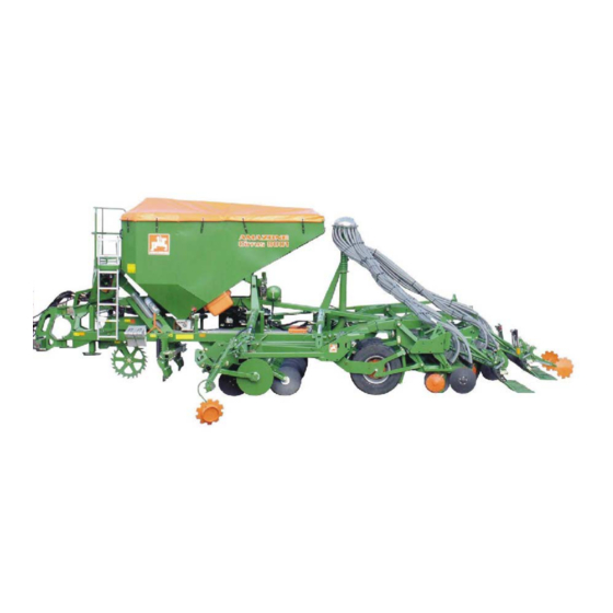
PacTeC Share Sowing Combinations with Integrated Running Gear
Please read this operating
manual before first
MG 1455
commissioning.
BAH0006 03.06
Keep it in a safe place for
Printed in Germany
future use.
1
Cirrus BAH0006 03.06
Advertisement
Table of Contents

Related Manuals for Amazone Cirrus 3001


Summary of Contents for Amazone Cirrus 3001
- Page 1 Operating Manual Cirrus 3001 Cirrus 4001 Cirrus 6001 Cirrus 8001 Cirrus 9001 PacTeC Share Sowing Combinations with Integrated Running Gear Please read this operating manual before first MG 1455 commissioning. BAH0006 03.06 Keep it in a safe place for Printed in Germany future use.
- Page 2 Reading the instruction manual and to adhere to it should not appear to be inconvenient and superfluous as it is not enough to hear from others and to realise that a machine is good, to buy it and to believe that now everything would work by itself.
- Page 3 Hasbergen Tel.: + 49 (0)5405 501-290 Fax: + 49 (0)5405 501-106 E-mail: et@amazone.de Online spare parts' catalogue: www.amazone.de When ordering spare parts, always specify the (ten-digit) machine identification number. Formalities of the operating manual Document number: MG 1455 Compilation date: 03.06...
- Page 4 Send us your suggestions by fax. AMAZONEN-WERKE H. DREYER GmbH & Co. KG Postfach 51 D-49202 Hasbergen Tel.: + 49 (0)5405 501-0 Fax: + 49 (0)5405 501-234 E-mail: amazone@amazone.de Cirrus BAH0006 03.06...
-
Page 5: Table Of Contents
Table of Contents User Information ..................9 Purpose of the document ....................9 Locations in the operating manual ..................9 Diagrams used ........................9 General Safety Instructions ..............10 Obligations and liability......................10 Representation of safety symbols..................12 Organisational measures....................13 Safety and protection equipment ..................13 Informal safety measures ....................13 User training........................14 Safety measures in normal operation.................15 Dangers from residual energy....................15... - Page 6 Table of Contents Dual-circuit pneumatic service braking system..............57 5.2.1 Coupling the brake and supply lines .................. 58 5.2.2 Uncoupling the brake and supply lines ................59 Hydraulic operating brake system..................60 5.3.1 Coupling the hydraulic operating brake system..............60 5.3.2 Uncoupling the hydraulic operating brake system ..............
- Page 7 Table of Contents 8.1.1 Table of seed dosing rollers....................99 8.1.2 Replacing the dosing roller ....................100 Setting the level sensor ....................101 Setting the sowing rate on ..............102 Calibration test ........................102 8.4.1 Preparing for the calibration test ..................103 8.4.2 Calibration test on the Cirrus with a Vario gearbox with seed volume adjustment.....104 8.4.3 Calibration test on the Cirrus with full dosing..............105 Fan speed ........................106...
- Page 8 Lower link pin........................181 12.6 Screw tightening torques....................182 Hydraulic plans..................184 13.1 Hydraulic plan of the Cirrus 3001..................184 13.2 Hydraulic plan of the Cirrus 4001/6001 ................186 13.3 Hydraulic plan of the Cirrus 8001/9001 ................188 Cirrus BAH0006 03.06...
-
Page 9: User Information
User Information User Information The User Information section supplies information on handling the operating manual. Purpose of the document This operating manual · Describes the operation and maintenance of the machine. · Provides important information on safe and efficient handling of the machine. -
Page 10: General Safety Instructions
General Safety Instructions General Safety Instructions This section contains important information on safe operation of the machine. Obligations and liability Comply with the instructions in the operating manual Knowledge of the basic safety information and safety regulations is a basic requirement for safe handling and fault-free machine operation. Obligations of the operator The operator is obliged only to let those people work with/on the machine who... - Page 11 General Safety Instructions Risks in handling the machine The machine has been constructed to the state-of-the art and the recognised rules of safety. However, there may be risks and restrictions which occur when operating the machine · For the health and safety of the user or third persons, ·...
-
Page 12: Representation Of Safety Symbols
General Safety Instructions Representation of safety symbols Safety instructions are indicated by the triangular safety symbol and the highlighted signal word. The signal word (DANGER, WARNING, CAUTION) describes the gravity of the risk and has the following significance: DANGER Indicates an immediate high risk, which will result in death or serious physical injury (loss of body parts or long term damage) if not avoided. -
Page 13: Organisational Measures
General Safety Instructions Organisational measures The operator must provide the necessary personal protective equipment, such as: · Protective glasses · Protective shoes · Protective suit · Skin protection agents etc. The operation manual · Must always be kept at the place at which the machine is operated. -
Page 14: User Training
General Safety Instructions User training Only those people who have been trained and instructed may work with/on the machine. The operator must clearly specify the responsibilities of the people charged with operation, maintenance and repair work. People being trained may only work with/on the machine under the supervision of an experienced person. -
Page 15: Safety Measures In Normal Operation
General Safety Instructions Safety measures in normal operation Only operate the machine if all the safety and protection equipment is fully functional. Check the machine at least once a day for visible damage and check the function of the safety and protection equipment. Dangers from residual energy Note that there may be residual mechanical, hydraulic, pneumatic and electrical/electronic energy on the machine. -
Page 16: Spare And Wear Parts And Aids
General Safety Instructions 2.10.1 Spare and wear parts and aids Immediately replace any machine parts which are not in a perfect state. Use only genuine spare and wear parts or the parts cleared by AMAZONEN-WERKE so that the operating permit retains its validity in accordance with national and international regulations. -
Page 17: Warning Pictograms And Other Signs On The Machine
General Safety Instructions 2.13 Warning pictograms and other signs on the machine Always keep all the warning pictograms of the machine clean and in a legible state. Replace illegible warning pictograms. You can obtain the warning pictograms from your dealer using the order number (e.g. - Page 18 General Safety Instructions Order number and explanation Warning pictograms MD 076 Danger of your hand or arm being drawn in or caught by a power driven, unprotected chain or belt drive! This hazard can cause extremely serious injuries with the loss of parts of the hand or arm. Never open or remove the guard devices on chains or belt drives ·...
- Page 19 General Safety Instructions MD 081 Danger of getting crushed for the whole body by machine parts that are raised by lifting cylinders and unintentionally lowered! This danger will cause serious injuries anywhere on the body or death. Secure the machine parts raised by the lifting cylinder against unintentional lowering before you enter the danger zone under raised machine parts.
- Page 20 General Safety Instructions MD 090 Risk of contusions from unintentional rolling of the uncoupled, unsecured machine! This danger will cause serious injuries anywhere on the body or death. Secure the machine against unintentional rolling, before uncoupling the machine from the tractor. For this, use the parking brake and/or the wheel chock(s).
- Page 21 General Safety Instructions MD 097 Danger of crushing your torso in the stroke range of the three-point suspension due to the narrowing spaces when the three-point hydraulic system is actuated! This danger causes extremely serious injuries and even death. Personnel are prohibited from entering the stroke area of the three-point suspension when the three-point hydraulics are actuated.
- Page 22 General Safety Instructions MD 104 Danger of your torso getting crushed by laterally swivelling machine parts! This danger will cause serious injuries to the torso or death. Maintain a sufficient safety distance between you and any moving machinery parts. It is forbidden to stand in the swivel area of moving machine parts.
-
Page 23: Positioning Of Warning Pictograms And Other Labels
General Safety Instructions 2.13.1 Positioning of warning pictograms and other labels Warning pictograms The following diagrams show the arrangement of the warning pictograms on the machine. Fig. 1 Fig. 2 Fig. 3 Fig. 4 Fig. 5 Cirrus BAH0006 03.06... - Page 24 General Safety Instructions Fig. 6 The following illustrations show warning symbols that are located only on folding machines. Fig. 7 Cirrus BAH0006 03.06...
-
Page 25: Dangers If The Safety Information Is Not Observed
General Safety Instructions 2.14 Dangers if the safety information is not observed Nonobservance of the safety information · Can pose both a danger to people and also to the environment and machine. · Can lead to the loss of all warranty claims. Seen individually, non-compliance with the safety information could pose the following risks: ·... -
Page 26: Safety Information For Users
General Safety Instructions 2.16 Safety information for users WARNING Risk of contusions, cuts, dragging, catching or knocks from insufficient traffic and operational safety. Before starting up the machine and the tractor, always check their traffic and operational safety. 2.16.1 General safety and accident prevention information ·... - Page 27 General Safety Instructions three-point hydraulic system. · When coupling and uncoupling machines, move the support equipment (if available) to the appropriate position (stability). · When actuating the support equipment, there is a danger of injury from contusion and cutting points! ·...
- Page 28 General Safety Instructions Use of the machine · Before starting work, ensure that you understand all the equipment and actuation elements of the machine and their function. There is no time for this when the machine is already in operation! ·...
- Page 29 General Safety Instructions the approved axle and support loads of the tractor. · The tractor must guarantee the prescribed brake delay for the loaded vehicle combination (tractor plus connected machine). · Check the brake power before moving off. · When turning corners with the machine connected, take the broad load and balance weight of the machine into account.
-
Page 30: Hydraulic System
General Safety Instructions 2.16.2 Hydraulic system · The hydraulic system is under a high pressure. · Ensure that the hydraulic hose lines are connected correctly. · When connecting the hydraulic hose lines, ensure that the hydraulic system is depressurised on both the machine and tractor sides. -
Page 31: Electrical System
General Safety Instructions 2.16.3 Electrical system · When working on the electrical system, always disconnect the battery (negative terminal). · Only use the prescribed fuses. If fuses are used that are too highly rated, the electrical system will be destroyed – danger of fire! ·... -
Page 32: Brake System
General Safety Instructions 2.16.5 Brake system · Only specialist workshops or recognised brake service may carry out adjustment and repair work on the brake system. · Have the brake system checked regularly. · If there are any functional faults in the brake system, stop the tractor immediately. -
Page 33: Tyres
General Safety Instructions Hydraulic braking system for export machines · Hydraulic brake systems are not approved in Germany. · When filling up or replacing the brake fluid, use the prescribed hydraulic fluids. When replacing the hydraulic fluids, comply with the appropriate regulations. 2.16.6 Tyres ·... -
Page 34: Cleaning, Maintenance And Repairs
General Safety Instructions 2.16.8 Cleaning, maintenance and repairs · Only carry out cleaning, maintenance and repair work on the machine when: The drive is switched off The tractor engine is at a standstill The ignition key has been removed The machine's connector has been disconnected from the on-board computer! ·... -
Page 35: Loading And Unloading
Loading and unloading Loading and unloading Loading and unloading with a tractor WARNING There is a risk of an accident when the tractor is unsuitable and the machine brake system is not connected to the tractor or is filled. · Correctly couple the machine to the tractor, before loading the machine onto a transport vehicle or unloading it from a transport vehicle. -
Page 36: Loading The Cirrus
Loading and unloading Loading the Cirrus 1. Put the Cirrus in its transport position (see section "Transportation", on page 120). 2. Raise the Cirrus via the integrated running gear up to a middle position (via control unit 1, see section 7.1.1.1, on page 92). 3. -
Page 37: Loading And Unloading The Cirrus 8001/9001 On Transport Trailers With A Central Spar
Loading and unloading Loading and unloading the Cirrus 8001/9001 on transport trailers with a central spar When loading and unloading the Cirrus 8001/9001 the two middle wheel links (Fig. 14/1) must be raised so that they do not collide with the central spar (Fig. - Page 38 Loading and unloading 7. Lower the Cirrus fully (control unit 1, see section 7.1.1.1, on page 92) as soon as the Cirrus has reached its transport position on the transport vehicle. 8. Secure the Cirrus in compliance with regulations. Bear in mind that the Cirrus has no parking brake.
- Page 39 Loading and unloading 5. Remove the tensioning belt (Fig. 13/1). WARNING Lower the Cirrus fully before removing the tensioning belt (Fig. 13/1). 6. Open the ball valve (Fig. 18/1) of the middle running gear cylinder. The open ball valve is illustrated. 7.
-
Page 40: Product Description
Product description Product description This section: · Provides a comprehensive overview of the machine structure. · Provides the names of the individual modules and controls. Read this section when actually at the machine. This helps you to understand the machine better. Main assemblies of the machine Fig. -
Page 41: Overview Of Subassemblies
Product description Overview of subassemblies Fig. 20/... (1) Draw rail (2) Sustainer, extendable Fig. 20 Fig. 21/... (1) Mounting for supply lines Fig. 21 Fig. 22/... (1) Wheel chocks (2) Platform with ladder (3) Holding point (4) Star wheel Fig. 22 Fig. - Page 42 Product description Fig. 24/... (1) Vario gearbox Fig. 24 Fig. 25/... (1) Calibration crank (in transport mounting) (2) Seed doser (3) Calibration trough (in mounting for calibration test) (4) Injector housing Fig. 25 Fig. 26/... (1) Sieve grate (2) Level sensor Fig.
- Page 43 Product description Fig. 28/... (1) Pre-emergence marker Fig. 28 Fig. 29/... (1) Brake valve with release valve (viewed from below) Fig. 29 Fig. 30/... (1) Electrohydraulic control blocks (2) Hydraulic accumulator with nitrogen filling for pretensioning the outswung machine extension arms Fig.
-
Page 44: Safety And Protection Equipment
Product description Safety and protection equipment Fig. 32/... (1) Guard panelling, electrohydraulic control blocks Fig. 32 Fig. 33/... (1) Hydraulic stop-cock anti-rotation lock (equalising system) Fig. 33 Fig. 34/... (1) Fan guard Fig. 34 Fig. 35/... (1) Sieve grate lock (for full dosing) Fig. - Page 45 Product description Fig. 36/... (1) Dosing window lock. Interruption of the roller drive when the dosing window is opened (Fig. 36/2) with full dosing. Fig. 36 Fig. 37/... (1) Spacer for safeguarding the axle rocker prior to servicing work. Fig. 37 Cirrus BAH0006 03.06...
-
Page 46: Overview - Supply Lines Between The Tractor And The Machine
Product description Overview – Supply lines between the tractor and the machine Fig. 38 Fig. 38/.. Designation Marking Hydraulic line 1 Feed line 1 cable tie, yellow Hydraulic line 1 Return line 2 cable ties, yellow Hydraulic line 2 Feed line 1 cable tie, green Hydraulic line 2 Return line... -
Page 47: Transportation Equipment
Product description Transportation equipment Fig. 39/... (1) 2 rear lights (2) 2 brake lights (3) 2 direction indicators (4) 2 red reflectors (round, rectangular or triangular) (5) 1 licence plate holder with lighting (6) 2 warning boards pointing to the rear (7) 1 road safety bar (8) 1 speed sign. -
Page 48: Intended Use
Product description Intended use The machine · is constructed for the seedbed preparation of agriculturally used arable land and for the dosing and output of commonly available seeds. · This is coupled to the tractor using the lower tractor line and is operated by an additional person. -
Page 49: Danger Area And Danger Points
Product description Danger area and danger points The danger area is the area around the machine in which people can be caught: · By work movements made by the machine and its tools · By materials or foreign bodies thrown out of the machine ·... -
Page 50: Nameplate And Ce Labelling
Product description Nameplate and CE labelling The following illustrations show the arrangement of the type plate (Fig. 42/1) and of the CE marking (Fig. 42/2). The nameplate shows: · Mach. ident. no. · Type · Permissible system pressure, bar · Year of manufacture ·... -
Page 51: Technical Data
Product description Technical data Cirrus Cirrus Cirrus Cirrus Cirrus 3001 4001 6001 8001 9001 Working width Filling height 2350 2350 2500 2800 2800 Total length 7.42 7.92 7.92 8.90 8.90 Hopper volume 2200 2200 3000 5000 5000 Full load (on field) [kg] 1800 1800... -
Page 52: Conformity
Necessary tractor equipment For operation of the machine in compliance with the intended use the tractor must fulfil the following requirements. Tractor engine power Cirrus 3001 from 90 kW (120 bhp) upwards Cirrus 4001 from 110 kW (150 bhp) upwards... -
Page 53: Noise Production Data
Product description Operational brake system · Dual-circuit service · braking system: 1 hose coupling (red) for the supply line · 1 hose coupling (yellow) for the brake line · Hydraulic 1 hydraulic coupling in accordance with ISO 5676 braking system: The hydraulic braking system is not allowed in Germany and several other EU countries! 4.11... -
Page 54: Structure And Function
Structure and function Structure and function The following section provides information on the machine structure and the functions of the individual components. Fig. 44 Cirrus PacTeC share sowing combinations make seeding possible with or without previous soil cultivation in one work process. With the disc array (Fig. -
Page 55: Hydraulic Hose Lines
Structure and function Hydraulic hose lines WARNING Danger of infection from escaping hydraulic fluid at high pressure! When coupling and uncoupling the hydraulic hose lines, ensure that the hydraulic system is depressurised on both the machine and tractor sides. If you are injured by hydraulic fluid, contact a doctor immediately. 5.1.1 Coupling the hydraulic hose lines WARNING... -
Page 56: Uncoupling The Hydraulic Hose Lines
Structure and function 5.1.2 Uncoupling the hydraulic hose lines 1. Swivel the actuation lever on the control valve on the tractor to float position (neutral position). 2. Unlock the hydraulic connectors from the hydraulic sockets. 3. Safeguard the hydraulic connectors and hydraulic connector sockets against soiling with the dust protection caps. -
Page 57: Dual-Circuit Pneumatic Service Braking System
Structure and function Dual-circuit pneumatic service braking system DANGER The Cirrus does not have a parking brake! Always secure the machine with the wheel chocks before you uncouple the machine from the tractor! Compliance with the maintenance intervals is essential for the correct function of the two-line operating brake system. -
Page 58: Coupling The Brake And Supply Lines
Structure and function 5.2.1 Coupling the brake and supply lines WARNING Risk of contusions, cuts, dragging, catching or knocks from incorrectly functioning brake system. · When coupling the brake and supply line, ensure that: the sealing rings of the hose couplings are clean the sealing rings of the hose couplings form a proper seal. -
Page 59: Uncoupling The Brake And Supply Lines
Structure and function 5. Remove the hose coupling of the supply line (red) from the empty coupling. 6. Check the sealing rings on the hose coupling for damage and cleanliness. 7. Clean the dirty sealing rings and replace any damaged sealing rings. -
Page 60: Hydraulic Operating Brake System
Structure and function Hydraulic operating brake system To control the hydraulic operating brake system, the tractor requires hydraulic braking equipment. 5.3.1 Coupling the hydraulic operating brake system Only couple clean hydraulic couplings. 1. Remove the protective cap (Fig. 52/1). 2. If necessary, clean the hydraulic connectors (Fig. -
Page 61: Seed Hopper And Seed Dosing
Structure and function Seed hopper and seed dosing The dosing roller of the seed doser (Fig. 53/2) doses the seed coming from the seed hopper (Fig. 53/1) into the air stream of the venturi cone (Fig. 53/3). The air stream conveys the seed through the seed feed tube to the distributor head (Fig. -
Page 62: Level Sensor
Structure and function For sowing particularly large seeds, e.g. beans, the chambers (Fig. 57/1) of the coarse dosing roller can be enlarged by repositioning the wheels and the plates. Fig. 57 Level sensor The level sensor monitors the seed level in the seed hopper. -
Page 63: Star Wheel
Structure and function Star wheel Via the Vario gearbox the star wheel drives the dosing rollers in the seed doser. With full dosing the star wheel is the roller feeler for distance. The rotational drive speed of the dosing rollers ·... -
Page 64: Full Dosing (Optional)
Structure and function Full dosing (optional) With full dosing one electric motor (Fig. 62/1) each drives a dosing roller. The rotational drive speed of the dosing roller is determined by the working speed and the preset sowing rate. A star wheel determines the working speed and the distance covered. -
Page 65: Blower
Structure and function 5.11 Blower The hydraulic motor (Fig. 64/2) drives the blower (Fig. 64/1) and generates an air current. The air current conveys the seeds from the venturi cone to the shares. The blower speed determines the air volume of the air current. -
Page 66: Tapered Ring Tyres
Structure and function 5.13 Tapered ring tyres The tapered ring tyres (Fig. 67/1) · are arranged individually next to one another · compact the cultivated soil in strips · assume depth guidance of the PacTeC shares (Fig. 67/2) for uniform seed depositing ·... -
Page 67: Pactec Share
Structure and function 5.14 PacTeC share Each PacTeC share (Fig. 70/1) · forms a sowing furrow in the compacted strips of the tapered ring tyres · deposits the seed into the sowing furrow. Fig. 70 The seed depositing depth is set by the support on the tapered ring tyres. -
Page 68: Exact Harroweeder
Structure and function 5.15 Exact harroweeder The exact harroweeder (Fig. 73/1) covers the seeds deposited in the sowing furrows with loose earth and smoothes the ground. The following are adjustable · The exact harroweeder position can be adjusted for adjustment to the set seed depth ·... -
Page 69: Markers
Structure and function 5.17 Markers The hydraulically-actuated markers dig into the ground alternately on the left and the right of the machine. In so doing, the active marker creates a mark. This mark serves as an orientation aid for the next run after turning. After turning, the tractor driver drives over the centre of the mark. -
Page 70: Operator Control Terminal
Structure and function 5.18 Operator control terminal consists of the operator control terminal (Fig. 78), the basic equipment (cable and fastening material) and the job computer on the machine. The following are performed via the operator control terminal · input of the machine-specific data ·... - Page 71 Structure and function For communication purposes the includes · the menu "Work" · the main menu with 4 submenus the menu "Job" the menu "Seed drill calibration" the menu "Machine data" the menu "Setup". the menu "Work" · indicates the requisite data for sowing operation ·...
-
Page 72: Distributor Head And Tramline Circuit
Structure and function 5.19 Distributor head and tramline circuit In the distributor head (Fig. 79/1) the seed is distributed uniformly over all the seed coulters. The number of distributor heads depends on the machine working width. A seed doser always supplies one distributor head. -
Page 73: Tramline Rhythm
Structure and function 5.19.1 Tramline rhythm Tramlines can be created on the field. Tramlines are seed-free tracks (Fig. 81/A) for fertilising and plant care machines used later. The tramline spacing (Fig. 81/b) corresponds to the working width of the care machines (Fig. 81/B), e.g. fertiliser spread and/or sprayer, which are used on sown fields. -
Page 74: 5.19.1.1 Examples For Creating Tramlines
Structure and function 5.19.1.1 Examples for creating tramlines The creation of tramlines is shown in Figure (Fig. 83) using various examples: Working width of the sowing machine Tramline spacing (= working width of fertiliser spreader / field sprayer) Tramline rhythm (input on the Tramline counter (during work the field runs are number consecutively and displayed on the Perform any inputs and outputs with the aid of the... - Page 75 Structure and function Fig. 83 Cirrus BAH0006 03.06...
-
Page 76: Tramline Rhythm 4, 6 And 8
Please refer to the instruction manual for an exact description On the Cirrus 3001/4001 it is not possible to switch a part of the width. Another option for creating tramlines with the tramline rhythm 4, 6 and 8 is to begin with the full working width and the creation of a tramline (see Fig. -
Page 77: 5.19.1.3 Tramline Rhythm 2 And 6Plus
Structure and function 5.19.1.3 Tramline rhythm 2 and 6plus Figure (Fig. 83) shows examples of tramline creation with tramline rhythms 2 and 6plus. When tramlines are created with the tramline rhythm 2 and 6plus (Fig. 85), tramlines are created during the trips forward and backward over the field. -
Page 78: Pre-Emergence Marker (Optional)
Structure and function 5.20 Pre-emergence marker (optional) Upon the creation of tramlines the pre- emergence marker (Fig. 86) drops automatically and the track discs mark the tramline that has just been created. Due to this the tramlines already become visible before the seed has been sown. -
Page 79: Commissioning
Commissioning Commissioning This section contains information · on initial operation of your machine · on checking how you may connect the machine to your tractor. · Before operating the machine for the first time the operator must have read and understood the operating manual. ·... -
Page 80: Checking The Suitability Of The Tractor
Commissioning Checking the suitability of the tractor WARNING Danger of breaking during operation, insufficient stability and insufficient tractor steering and braking power on improper use of the tractor! · Check the suitability of your tractor before you attach or hitch the machine to the tractor. -
Page 81: Data Required For The Calculation (Hitched Machine)
Commissioning 6.1.1.1 Data required for the calculation (hitched machine) Fig. 89 [kg] Empty tractor weight See tractor operating manual or vehicle documentation [kg] Front axle load of the empty tractor [kg] Rear axle load of the empty tractor [kg] Front weight (if available) See front weight in technical data, or weigh [kg] Maximum drawbar load See technical data of machine... -
Page 82: Of The Tractor For Assurance Of The Steering Capability
Commissioning 6.1.1.2 Calculation of the required minimum ballasting at the front G of the tractor for V min assurance of the steering capability · · · · Enter the numeric value for the calculated minimum ballast G V min required on the front side of the tractor, in the table (Section 6.1.1.7). 6.1.1.3 Calculation of the actual front axle load of the tractor T V tat... -
Page 83: Table
Commissioning 6.1.1.7 Table Actual value according to Approved value Double approved calculation according to tractor load capacity (two instruction manual tyres) Minimum ballast front / rear £ Total weight £ £ Front axle load £ £ Rear axle load · You can find the approved values for the total tractor weight, axle loads and load capacities in the tractor registration papers. -
Page 84: Requirements For Tractor Operation With Attached Machines
Commissioning 6.1.2 Requirements for tractor operation with attached machines WARNING Risk of breakage during operation of components through unapproved combinations of connecting equipment! Ensure: · that the connection device on the tractor has a sufficient permissible noseweight for the noseweight actually in question ·... -
Page 85: Securing The Tractor / Machine Against Unintentional Start-Up And Rolling
Commissioning Securing the tractor / machine against unintentional start-up and rolling WARNING Risk of contusions, cutting, catching, drawing in and knocks when making interventions in the machine through · unintentional lowering of the unsecured machine when it is raised via the three-point hydraulic system of the tractor ·... -
Page 86: Installation Regulations For The Hydraulic Fan Drive Connection
Commissioning Installation regulations for the hydraulic fan drive connection The banking-up pressure of 10 bar must not be exceeded. The installation regulations therefore have to be complied with when connecting the hydraulic fan connection. · Connect the hydraulic coupling of the pressure line (Fig. 90/5) to a single-acting or double-acting tractor control unit with priority. -
Page 87: Initial Installation Of The
Commissioning Initial installation of the Install the terminal (Fig. 91) of the in the tractor cab with the aid of the operating manual Fig. 91 Cirrus BAH0006 03.06... -
Page 88: Coupling And Uncoupling The Machine
Coupling and uncoupling the machine Coupling and uncoupling the machine When coupling and uncoupling the machine take heed of the section "Safety information for users", on page 26. WARNING Risk of contusions from unintentional starting and rolling of the tractor and machine when coupling or uncoupling the machine! Secure the tractor and machine against unintentional start-up and rolling away before entering the danger area between the tractor and machine to couple or uncouple the machine. - Page 89 The Cirrus can be coupled or uncoupled whether it is folded in or out (except Cirrus 3001). Always retract the integrated running gear beforehand (lower the machine). When the machine is uncoupled and the running gear is...
- Page 90 The balls of the lower linkage are dependent on the tractor type (see tractor operating manual). The Cirrus 3001 and Cirrus 4001 can be equipped with lower link pins (Cat. II). Fig. 93 CAUTION Danger of getting crushed in the area of the moving draw rail.
- Page 91 Coupling and uncoupling the machine machine before you approach the machine with the tractor. 6. Drive the tractor in reverse up to the machine so that the lower link hooks of the tractor automatically pick up the ball of the lower linking points of the machine.
-
Page 92: Connecting The Hydraulic Connections
Coupling and uncoupling the machine 7.1.1.1 Connecting the hydraulic connections · Clean the hydraulic couplings before connecting them to the tractor. Minor oil impurities from particles can cause a failure of the hydraulic system. · Where possible use only tractor control units with a settable oil flow rate. -
Page 93: Connecting The Electrical Connections
Coupling and uncoupling the machine 7.1.1.2 Connecting the electrical connections Connection/function Installation information Plug (7-pin) for the road traffic lighting system Connect the plugs to the terminal as described in machine plug operating manual. 7.1.1.3 Connecting the pneumatic service brake system Tractor connection Function Connection... -
Page 94: Connecting The Hydraulic Service Brake System
Coupling and uncoupling the machine 7.1.1.4 Connecting the hydraulic service brake system Required on the tractor face is an hydraulic braking device that drives the hydraulic braking system of the Cirrus (not allowed in Germany and several other EU countries). Connect the hydraulic brake connection (Fig. -
Page 95: Uncoupling The Machine
Coupling and uncoupling the machine Uncoupling the machine WARNING Risk of contusions, cutting, catching, drawing in and knocks through insufficient stability and possible tilting of the uncoupled machine! Set the empty machine down on a horizontal parking area with a firm base. - Page 96 Coupling and uncoupling the machine 7. Secure the Cirrus on each side of the machine by placing 2 wheel chocks each (Fig. 99) under the outer tapered ring tyres. DANGER Always secure the machine with 4 wheel chocks before you uncouple the machine from the tractor! The wheel chocks replace the machine's parking...
- Page 97 Coupling and uncoupling the machine 14. Set the Cirrus down on the sustainer. WARNING Set the machine down on a horizontal, firm base only! Ensure that the sustainer does not sink into the ground. If the sustainer does sink into the ground, it will be impossible to recouple the machine! Fig.
-
Page 98: Settings
Settings Settings WARNING Risk of contusions, cutting, catching, drawing in and knocks through · Unintentional falling of the machine raised using the tractor's three-point hydraulic system. · Unintentional falling of raised, unsecured machine parts. · Unintentional start-up and rolling of the tractor-machine combination. -
Page 99: Table Of Seed Dosing Rollers
Settings 8.1.1 Table of seed dosing rollers Seed Dosing roller Seed Dosing roller Spelt wheat Coarse dosing roller Rape Fine dosing roller Oats Coarse dosing roller Red clover Fine dosing roller Coarse dosing roller or Medium dosing roller or Mustard medium dosing roller fine dosing roller Spring barley... -
Page 100: Replacing The Dosing Roller
Settings 8.1.2 Replacing the dosing roller 1. Remove the folding plug (Fig. 105/2) (only necessary to close the filled seed hopper with the slider (Fig. 105/1). The dosing rollers can be replaced more easily, if the seed hopper is empty Fig. -
Page 101: Setting The Level Sensor
Settings 5. Pull the dosing roller out of the seed doser. 6. Refer to table (Fig. 104, on page 99) for the requisite dosing roller and install in the reverse order. 7. Equip all the seed dosing units with the same dosing roller. -
Page 102: Setting The Sowing Rate On
Settings Increase the residual seed volume, which triggered the alarm: · the coarser the seeds · the greater the sowing rate · the greater the working width. Setting the sowing rate on To set the sowing rate on the 1. Open the menu "Job". 2. -
Page 103: Preparing For The Calibration Test
Settings 8.4.1 Preparing for the calibration test CAUTION During preparation for the calibration test: 1. Shut down the tractor engine 2. Apply the parking brake 3. Remove the ignition key. 1. Fill the seed hopper with at least 200 kg of seed (in the case of fine seeds correspondingly less). -
Page 104: Calibration Test On The Cirrus With A Vario Gearbox With Seed Volume Adjustment
Settings 4. Open the venturi cone flap (Fig. 113/1) on all seed dosing units. CAUTION Risk of contusions on opening and closing the venturi cone flap (Fig. 113/1)! Hold the venturi cone flap only by the lug (Fig. 113/2), otherwise there is a risk of injury when the spring-loaded venturi cone flap snaps closed. -
Page 105: Calibration Test On The Cirrus With Full Dosing
Settings During the calibration test the requests that the calibrating crank handle be turned counterclockwise until a signal tone sounds. The number of crank handle turns for the calibration test until the signal tone sounds is governed by the sowing rate and the calibrated area: ·... -
Page 106: Fan Speed
Settings Fan speed DANGER Do not exceed the maximum fan speed of 4000 rpm. The fan speed alters until the hydraulic fluid has reached its working temperature. On initial operation correct the fan speed up to attainment of the working temperature. If the fan is put back into operation after a long stoppage period, the preset fan speed is not attained until the hydraulic fluid has heated up to working temperature. -
Page 107: Setting The Fan Speed Via The Flow Control Valve Of The Tractor
Settings 8.5.2 Setting the fan speed via the flow control valve of the tractor 1. Remove the protective cap (Fig. 117/1) from the machine's pressure control valve. 2. Loosen the lock nut. 3. Close the pressure control valve. To do so, turn the screwdriver clockwise. -
Page 108: Setting The Fan Speed Monitoring On The
Settings 8.5.4 Setting the fan speed monitoring on the Set the fan speed monitoring on the Machine Data menu (see operating manual) · input the fan speed (rpm) that is to be monitored or · adopt the current fan speed (rpm) during operation as the speed to be monitored. -
Page 109: Setting The Seed Depositing Depth
Settings Setting the seed depositing depth 1. Switch off the low lift function (see operating manual). WARNING Direct people out of the danger area. 2. Lift the machine until the bracket (Fig. 119/1) is freed from the depth regulation bolt (Fig. - Page 110 Settings 5. After each repositioning secure the depth regulation bolt with linch pins (Fig. 121/1). Fig. 121 WARNING Direct people out of the danger area. 6. Lower the machine. The brackets (Fig. 122/1) are supported on the depth regulation bolts (Fig. 122/2). 7.
-
Page 111: Adjusting The Marker
The table values specify the distance "A" (Fig. 123) · from the centre of the machine · up to the contact surface of the track marker disc. Distance "A" Cirrus 3001 3.0m Cirrus 4001 4.0m Cirrus 6001 6.0m Cirrus 8001 8.0m Cirrus 9001 9.0m... -
Page 112: Adjusting The Working Intensity Of The Markers
The numbers on the scale (Fig. 126/1) are for the purpose of orientation for setting different disc working depths. The higher the number, the greater the disc working depth. The scale of the (Fig. 127/1) Cirrus 3001 is located on the loading plate. Fig. 127 Cirrus BAH0006 03.06... -
Page 113: Setting The Length Of The Outer Disc Struts
If yes, correct the outside hollow disc setting. Fig. 129 CAUTION Danger of getting crushed when adjusting the outside hollow discs. The outside hollow discs of the Cirrus 3001 are folded inwards for transport (see section 9, on page 120). Cirrus BAH0006 03.06... -
Page 114: Setting The Track Loosener
To avoid damage when setting down the machine · fasten the rigid track looseners (Cirrus 3001, Cirrus 4001 and Cirrus 6001) at the very top after work and do not put them in working position until you are on the field. -
Page 115: Exact Harroweeder
Settings 8.10 Exact harroweeder 8.10.1 Harroweeder spring tine position Set the spring tines of the exact harroweeder so that they: · Are horizontal on the ground and · Have 5 - 8 cm free floating space beneath. The distance of the harroweeder frame from the ground is between 230 and 280 mm (see Fig. -
Page 116: Harroweeder Pressure
Settings 8.10.2 Harroweeder pressure The harroweeder pressure is set with the bolt. The higher a bolt is inserted into the adjusting segment, the greater is the harroweeder pressure. Harroweeders with hydraulic pressure adjustment have two bolts for different soils. Perform the same settings on all adjusting segments. 8.10.2.1 Setting the harroweeder pressure 1. -
Page 117: Setting The Tramlining Rhythm/Meter On The
Settings 8.10.3 Setting the tramlining rhythm/meter on the 1. Select the tramlining rhythm (see table, Fig. 82, on page 73). 2. Set the tramlining rhythm on the Machine Data menu (see operating manual). 3. Refer to Fig. (Fig. 83 on page 75) for the tramline counter of the first field run. -
Page 118: Pre-Emergence Marker (Optional)
Settings 8.11 Pre-emergence marker (optional) 8.11.1 Track disc carrier in operating / transport position Put the track disc carrier in operating position: 1. Hold the track disc carrier tight. 2. Remove the bolt (Fig. 136/1) that is secured with a slit pin (Fig. 136/2). Fig. -
Page 119: Setting The Track Width And Working Intensity Of The Pre-Emergence Marker
Settings 8.11.2 Setting the track width and working intensity of the pre-emergence marker 1. Direct people out of the danger area. 2. Set the tramline counter to "zero" (see operating manual). 3. Actuate control unit 1 and lower the track discs. 4. -
Page 120: Transportation
Transportation Transportation When driving on public roads and ways the tractor and machine must comply with the national road traffic regulations (in Germany the StVZO and the StVO) and the accident prevention regulations (in Germany those of the industrial injury mutual insurance organisation). - Page 121 Transportation WARNING Risk of contusions, cuts, dragging, catching or knocks from tipping and insufficient stability. · Drive in such a way that you always have full control over the tractor with the attached machine. In so doing, take your personal abilities into account, as well as the road, traffic, visibility and weather conditions, the driving characteristics of the tractor and the connected machine.
- Page 122 Transportation WARNING Danger of cuts during transport journeys with the outer harroweeder elements extended! Extended outer harroweeder elements extend laterally into the traffic area during transport journeys and endanger other road users. In addition the permissible transport width of 3 m is exceeded. Push the outer harroweeder elements into the main tube of the harroweeder before you perform any transport journeys.
- Page 123 Transportation When not in use the cover hook (Fig. 141/1) remains inserted in the transport mounting (Fig. 141/2) on the lighting beam. Fig. 141 4. Lift up and lock the ladder (Fig. 142). CAUTION Danger of getting crushed. Hold the ladder by the rungs only. Fig.
- Page 124 Transportation Cirrus 3001 only 7. Close the track marker hydraulic stop- cocks. There is a hydraulic stop-cock next to each track marker (Fig. 144/3). The hydraulic stop-cock can assume two positions: · Hydraulic stop-cock open (see Fig. 144/1) · Hydraulic stop-cock closed (see Fig. 144/2).
- Page 125 Transportation 9. Swivel the left-hand outside hollow disc (Fig. 147/1) to transport position. The outside hollow disc is fastened in transport position and in operating position to the lug (Fig. 147/2), positioned with a bolt (Fig. 147/3) and secured with a linch pin. Fig.
- Page 126 Transportation All types 12. Push the two-part transport securing bar (Fig. 149/1) over the tine tips of the harroweeder. 13. Fasten the transport securing bar with spring holders (Fig. 149/2) to the harroweeder. Fig. 149 14. Fold in the machine's extension arm (see section 10.2, on page 130).
- Page 127 Transportation 16. Check the lighting system for operability (see section "Transportation equipment", on page 47). 17. The warning boards and yellow reflectors must be clean and undamaged. Fig. 152 The maximum speed of the machine is 40 km/h. In particular on bad roads and ways driving may only take place at a considerably lower speed than specified! Switch on the all round lighting (if present), which is subject to authorisation, prior to starting a journey and check for operability.
-
Page 128: Use Of The Machine
Use of the machine Use of the machine When using the machine, observe the information in the sections · "Warning pictograms and other signs on the machine", as of on page 17 and · "Safety information for users", on page 26. Observing this information is important for your safety. -
Page 129: Removing The Transport Safety Bar
Use of the machine 10.1 Removing the transport safety bar 1. Release the spring holder (Fig. 153/2) and remove the transport safety bar (Fig. 153/1). 2. Fasten the transport safety bar to the transport mounting. Fig. 153 Cirrus BAH0006 03.06... -
Page 130: Folding The Machine Extension Arm Out And In
Use of the machine 10.2 Folding the machine extension arm out and in DANGER Instruct people to leave the swivel area of machine's extension arm before you fold the machine's extension arm out or in. Fig. 154 Align the tractor and machine straight on a flat surface before you fold the machine's extension arm out or in! Always raise the machine fully before you fold the machine's extension arm out or in. - Page 131 Use of the machine 7. Actuate control unit 2 until the machine extension arm is folded out. 8. Actuate control unit 2 for a further 3 secs. so that the hydraulic accumulator (Fig. 224) is filled with hydraulic fluid. Fig. 156 The locking hooks (Fig.
-
Page 132: Folding In The Machine's Extension Arm
Use of the machine 10.2.2 Folding in the machine's extension arm 1. Release the parking brake and take your foot off the brake pedal. Never leave the tractor cab with the parking brake released. 2. Actuate control unit 1 until the machine is fully raised (see Fig. - Page 133 Use of the machine The locking hooks (Fig. 160/1) form the mechanical transport locking device and engage onto the locking spigot (Fig. 160/2). DANGER Check whether the bars (Fig. 160/1) are engaged properly after folding in the extension arms. Fig. 160 10.
-
Page 134: Filling The Seed Hopper
Use of the machine 10.3 Filling the seed hopper DANGER Fill the seed hopper on the field only! Transport journeys on roads and ways are prohibited when the seed hopper is filled. The brake system is designed only for an empty machine. - Page 135 Use of the machine 6. Climb on the loading plate via the ladder. 7. Release the rubber loops on the end face. 8. Open the swivel cover. 9. If necessary, remove foreign bodies in the seed hopper. 10. Set the level sensor (see section 8.2, on page 101).
-
Page 136: Load The Seed Hopper With Sacked Merchandise From A Supply Vehicle
Use of the machine 10.3.1 Load the seed hopper with sacked merchandise from a supply vehicle 1. Approach the open loading edge of the trailer with the Cirrus. 2. Put the tractor on an extreme steering lock (approx. 90° to the Cirrus). 3. -
Page 137: Loading The Seed Hopper From Bulk Bags
Use of the machine 10.3.3 Loading the seed hopper from bulk bags 1. Set the Cirrus down on a flat surface. 2. Apply the parking brake, shut off the tractor engine and remove the ignition key. 3. Approach the machine carefully with the bulk bag. -
Page 138: Work Commencement
Use of the machine 10.4 Work commencement Upon commencement of work: 1. Direct people out of the danger area. 2. Move the machine to working position at the start of the field. 3. Actuate control unit 1. This executes the following hydraulic functions: lowering of the machine lowering of the star wheel lowering of the track marker... -
Page 139: During The Work
Use of the machine 10.5 During the work Percentual change in the sowing rate during the work During the work the sowing rate (100 %) can be increased in the Work menu by pressing a button (e.g. +10 %) or reduced (e.g. -10 %) or reset to 100 %. -
Page 140: Turning At End Of The Field
Use of the machine 10.6 Turning at end of the field Before turning at the end of the field: 1. Slow down your travel speed. 2. Do not reduce the tractor's rotational speed too far so that the hydraulic functions continue without interruption at the headland. -
Page 141: Emptying The Seed Dosing Unit And/Or Seed Hopper
Use of the machine 10.7 Emptying the seed dosing unit and/or seed hopper 1. Apply the parking brake, switch off the tractor engine and remove the ignition key! 2. Fasten the calibrating trough(s) under the seed dosing unit(s). Fig. 171 3. - Page 142 Use of the machine 5. Open the remainder emptying flap by turning the handle (Fig. 174/1). For emptying it is also possible to demount the dosing roller (see section 8.1.2, on page 100). Fig. 174 6. Turn the star wheel (Fig. 175), as in the calibration test with the calibrating handle, counterclockwise until the dosing roller(s) and seed dosing unit are completely...
-
Page 143: End Of Work On The Field
(see operating manual 4. Empty the seed hopper (see section 10.7, on page 141). 5. Fold in the machine extension arm (except for the Cirrus 3001) (see section 10.2, on page 130). Only actuate the tractor control units from inside the tractor cab! -
Page 144: Faults
Faults Faults WARNING Risk of contusions, cutting, catching, drawing in and knocks through · Unintentional falling of the machine raised using the tractor's three-point hydraulic system. · Unintentional falling of raised, unsecured machine parts. · Unintentional start-up and rolling of the tractor-machine combination. - Page 145 Faults Working in emergency mode: 1. Shut down the tractor engine, apply the parking brake and remove the ignition key. 2. Remove the guard panelling on the electrohydraulic control blocks (Fig. 177). 3. Undo the Allen screw (Fig. 177/1) up to the stop.
-
Page 146: Deviations Between The Preset And Actual Sowing Rates
Faults After repair · Screw in the Allen screw (Fig. 177/1). · Put the two valve pins (Fig. 178/1) in their normal position. 11.3 Deviations between the preset and actual sowing rates Possible causes that can lead to a deviation between the preset and actual sowing rates: ·... -
Page 147: Fault Table
Faults 11.4 Fault table Fault Possible cause Remedy Track marker not changing Work position sensor wrongly Set the sensor Work position sensor defective Replace the work position sensor Hydraulic valve jamming Replace the hydraulic valve Track marker switching too Working position sensor Set the sensor early or too late wrongly set... -
Page 148: Cleaning, Maintenance And Repairs
Cleaning, maintenance and repairs Cleaning, maintenance and repairs WARNING Risk of contusions, cutting, catching, drawing in and knocks through · Unintentional falling of the machine raised using the tractor's three-point hydraulic system. · Unintentional falling of raised, unsecured machine parts. ·... -
Page 149: Cleaning
Cleaning, maintenance and repairs DANGER If the machine is not fully raised · the shares can suddenly shoot to the rear and upwards at any time and cause extremely serious injuries · never remain in the share swivelling area. Danger of injury when cleaning the shares, if the machine is not fully raised. -
Page 150: Cleaning The Machine
Cleaning, maintenance and repairs Clean with a pressure cleaner / steam cleaner · Always observe the following points when using a high pressure cleaner / steam jet for cleaning: Do not clean any electrical components. Do not clean any chromed components. Never aim the cleaning jet from the nozzle of the high pressure cleaner / steam jet directly on lubrication and bearing points. -
Page 151: Cleaning The Distributor Head (Workshop)
Cleaning, maintenance and repairs 12.1.2 Cleaning the distributor head (workshop) 1. Fold out the machine's extension arm (see section 10.2.1, on page 130). 2. Apply the parking brake, switch off the tractor engine and remove the ignition key. WARNING Apply the parking brake, switch off the tractor engine and remove the ignition key. -
Page 152: Lubrication Regulations
Cleaning, maintenance and repairs 12.2 Lubrication regulations · Lubricate the machine in accordance with the specifications of the manufacturer. · Carefully clean the lubrication nipple and grease gun before lubrication so that no dirt is pressed into the bearings. Press the dirty grease completely into the bearings and replace it with new grease. -
Page 153: Lubrication Point Overview
Cleaning, maintenance and repairs 12.2.2 Lubrication point overview Number of lubrication nipples Lubrication interval Fig. 187/1 25 h Fig. 187/2 25 h Fig. 188/1 25 h Fig. 188/2 25 h Fig. 189/1 25 h 50 h Fig. 191/1 25 h 50 h Fig. -
Page 154: 12.2.2.1 Lubricating The Lubrication Nipples When The Machine Is Folded Out And Lowered
Cleaning, maintenance and repairs 12.2.2.1 Lubricating the lubrication nipples when the machine is folded out and lowered 1. Fold out the machine extension arm (see section 10.2.1, on page 130). 2. Lower the machine. 3. Apply the parking brake, shut down the tractor engine and remove the ignition key. -
Page 155: 12.2.2.2 Lubricating The Lubrication Nipple When The Machine Is Raised
Cleaning, maintenance and repairs 12.2.2.2 Lubricating the lubrication nipple when the machine is raised DANGER Secure the raised machine with spacers (Fig. 190/1). The spacers will prevent the machine from lowering, if the hydraulic line is defective. Lubricate the lubrication nipple when the machine is raised: 1. -
Page 156: Service Plan - Overview
Cleaning, maintenance and repairs 12.3 Service plan – overview · Carry out maintenance work when the first interval is reached. · The times, continuous services or maintenance intervals of any third party documentation shall have priority. Before initial operation Specialist Check and service the hydraulic Section 12.3.6 workshop... - Page 157 Cleaning, maintenance and repairs Every 3 months, at the latest Check the brake lining thickness Section 12.3.9.4 Specialist every 500 operating hours workshop External testing of the Section 12.3.8.2 compressed air tank of the dual- circuit pneumatic braking system Section 12.3.8.3 Specialist Check the pressure in the workshop...
-
Page 158: Wheel Bolts And Hub Tightening Torques (Specialist Workshop)
Cleaning, maintenance and repairs 12.3.1 Wheel bolts and hub tightening torques (specialist workshop) Tightening Fig. 193/… Bolt torque Wheel bolt 325 Nm M18 x 1.5 Bolt 600 Nm M20 x 1.5 10.9 Fig. 193 12.3.2 Tyre pressure Tyres Tyre pressure Running gear tyres (Fig. -
Page 159: Sowing Shaft Bearings
Cleaning, maintenance and repairs 12.3.4 Sowing shaft bearings Lightly grease the seat of the sowing shaft bearing with a thin mineral oil (SAE 30 or SAE 40). Fig. 195 12.3.5 Oil level in the Vario gearbox There is no need to change the oil. Checking the oil level in the Vario gearbox: 1. -
Page 160: Hydraulic System
Cleaning, maintenance and repairs 12.3.6 Hydraulic system WARNING Risk of infection through the high pressure hydraulic fluid of the hydraulic system entering the body! · Only a specialist workshop may carry out work on the hydraulic system. · Depressurize the hydraulic system before carrying out work on the hydraulic system. -
Page 161: 12.3.6.1 Labelling Hydraulic Hose Lines
Cleaning, maintenance and repairs 12.3.6.1 Labelling hydraulic hose lines The assembly labelling provides the following information: Fig. 198/... (1) Manufacturer's marking on the hydraulic hose line (A1HF) (2) Date of manufacture of the hydraulic hose line (04/02 = Year / Month = February 2004) (3) Maximum approved operating pressure (210 BAR). -
Page 162: 12.3.6.4 Installation And Removal Of Hydraulic Hose Lines
Cleaning, maintenance and repairs · Installation requirements not complied with. · Life span of 6 years has been exceeded. The date of manufacture of the hydraulic hose line on the assembly is decisive for determining these six years. If the date of manufacture on the assembly is "2004", then the hose should not be used beyond February 2010. -
Page 163: System
Cleaning, maintenance and repairs 12.3.7 Service brake system: dual-circuit pneumatic braking system - hydraulic braking system The Cirrus is equipped with a dual-circuit pneumatic braking system with a hydraulically actuated brake cylinder. The dual-circuit pneumatic braking system does not actuate as normally a rod or brake cable connected to the brake shoe. -
Page 164: Checking The Service Brake System For Safe Operating Condition (Specialist Workshop)
Cleaning, maintenance and repairs General visual check Carry out a general visual check of the brake system. Observe and check the following criteria: · Piping, hose lines and hose couplings must not be externally damaged or rusted. · Hinges, e.g. on fork heads, must be properly secured, easy to move, and not worn out. -
Page 165: Dual-Circuit Pneumatic Braking System
Cleaning, maintenance and repairs 12.3.8 Dual-circuit pneumatic braking system 12.3.8.1 Draining the compressed air reservoir 1. Run the tractor engine (approx. 3 mins.), until the compressed air reservoir (Fig. 199/1) has filled. 2. Shut down the tractor engine, apply the parking brake and remove the ignition key. -
Page 166: Checking The Pressure In The Compressed Air Reservoir (Specialist Workshop)
Cleaning, maintenance and repairs 12.3.8.3 Checking the pressure in the compressed air reservoir (specialist workshop) 1. Connect a pressure gauge to the test connection on the compressed air reservoir. 2. Run the tractor engine (approx. 3 mins.) until the compressed air reservoir has filled. -
Page 167: Hydraulic Braking System
Cleaning, maintenance and repairs 12.3.9 Hydraulic braking system 12.3.9.1 Checking the brake fluid level The equalising tank (Fig. 202) is filled in accordance with DOT 4 up to the "max." marking with brake fluid. The brake fluid must be between the marks "max."... -
Page 168: Brake Check On The Hydraulic Part Of The Braking System (Specialist Workshop)
Cleaning, maintenance and repairs 12.3.9.3 Brake check on the hydraulic part of the braking system (specialist workshop) Brake check on the hydraulic part of the braking system: · check all flexible brake hoses for wear · check all brake lines for damage ·... - Page 169 Cleaning, maintenance and repairs Carefully open the venting valves so that they are not turned off. It is recommended that the valves be sprayed with a rust releasing agent for approx. 2 hours before venting. Perform a safety check: · Are the venting screws tightened? ·...
-
Page 170: Elimination Of Malfunctions And Repair Work - Overview
Cleaning, maintenance and repairs 12.4 Elimination of malfunctions and repair work - Overview Adjusting the marker Setting the track markers Section 12.4.2 for correct threading into the transport mounting Setting the tramline to Section 12.4.1 Specialist tractor track width workshop Repair of the equalising Section 12.4.3 Specialist... -
Page 171: Setting The Tramline To The Tractor's Track (Specialist Workshop)
Cleaning, maintenance and repairs 12.4.1 Setting the tramline to the tractor's track (specialist workshop) When the machine is delivered or when buying a new tractor, check that the tramline set in the distributor head is set to the wheel gauge of the tractor. -
Page 172: Adjusting The Track (Activate Or Deactivate The Sliders)
Cleaning, maintenance and repairs 12.4.1.1 Adjusting the track (activate or deactivate the sliders) The track of the tramline increases if the number of tramline shares arranged next to each other increases. Six tramline shares can be connected to one distributor head. The sliders close the feed lines to the tramline shares. -
Page 173: Setting The Track Markers For Correct Threading Into The Transport Mounting
Cleaning, maintenance and repairs 12. Install the foam insert (Fig. 206/1). 13. Install the inner distributor cover (Fig. 206/2). 14. Install the ring (Fig. 206/3). 15. Install the outer distributor cover (Fig. 206/4). 16. Check the function of the tramline circuit. Fig. -
Page 174: Repair Of The Equalising System (Specialist Workshop)
Cleaning, maintenance and repairs 12.4.3 Repair of the equalising system (specialist workshop) Each tapered tyre is supported by two hydraulic cylinders (Fig. 208/1). The hydraulic cylinders of one half of the machine are connected to a closed hydraulic circuit. The two closed hydraulic circuits are designated as an equalising system. -
Page 175: 12.4.3.1 Draining, Filling And Calibrating (Specialist Workshop) The Equalising System
4. Raise the disc array. 5. Align the Cirrus straight on a flat surface. 6. Fold out the Cirrus (except for Cirrus 3001) (see section 10.2, on page 130). 7. Switch off the low-lift function. 8. Position the depth regulation bolt (Fig. - Page 176 Cleaning, maintenance and repairs To empty the equalising system each hydraulic circuit is equipped with a hydraulic stop-cock (Fig. 211/1). The hydraulic stop-cocks are equipped with an anti- rotation lock (Fig. 211/2). Figure (Fig. 211) shows the anti-rotation locked hydraulic stop-cock when it is closed. Fig.
- Page 177 Cleaning, maintenance and repairs Flushing the equalising system The hydraulic circuits of the equalising system are connected to a supply line for the hydraulic cylinder of the harroweeder (also if the harroweeder pressure adjustment is mechanical). The connections are closed with the hydraulic stop-cocks in the lever position indicated (Fig.
- Page 178 Cleaning, maintenance and repairs 10. Close both hydraulic stop-cocks (Fig. 217) of the equalising system. The illustration (Fig. 217) shows the hydraulic stop-cock closed. Fig. 217 Filling the equalising system 1. Lower the machine (control unit 1). The piston rod (Fig. 218/1) of the lift-out accumulator must be fully retracted.
- Page 179 Cleaning, maintenance and repairs Calibrating the equalising system 1. Measure the frame height (see Fig. 220) from the wheel contact surface. 2. The machine is correctly calibrated when both frame halves are set to a height of 825 mm. Fig. 220 The measuring edges of the machine are marked with stickers (Fig.
-
Page 180: Repairs To The Pressure Tank (Specialist Workshop)
Cleaning, maintenance and repairs 12.4.4 Repairs to the pressure tank (specialist workshop) Functional description of the pressure tank For re-compaction of the soil the tapered ring tyres are subjected to the weight of the machine. The weight of the machine also has to be conducted via the folding cylinders into the tapered ring tyres which are fastened to the extension arms. -
Page 181: Repair Of The Share Unit (Specialist Workshop)
Cleaning, maintenance and repairs 12.4.5 Repair of the share unit (specialist workshop) Installation and demounting of the draw springs (Fig. 225/1) is only possible with special tools. DANGER Use special tools. Danger of injury if the spring is installed or demounted with unsuitable tools. -
Page 182: Screw Tightening Torques
Cleaning, maintenance and repairs 12.6 Screw tightening torques Tightening torques [Nm] Width across depending on the quality of the nuts/bolts Thread flats [mm] 10.9 12.9 M 8x1 M 10 16 (17) M 10x1 M 12 18 (19) M 12x1.5 M 14 M 14x1.5 M 16 M 16x1.5... - Page 183 Cleaning, maintenance and repairs Cirrus BAH0006 03.06...
-
Page 184: Hydraulic Plans
Hydraulic plans Hydraulic plans 13.1 Hydraulic plan of the Cirrus 3001 Fig. 227/… Designation Share lift-out Pre-emergence marker Equalising system left Equalising system right Lift-out accumulator Harroweeder pressure adjustment Running gear Star wheel T11a Track marker left T11b Track marker right... - Page 185 Hydraulic plans Fig. 227 Cirrus BAH0006 03.06...
-
Page 186: Hydraulic Plan Of The Cirrus 4001/6001
Hydraulic plans 13.2 Hydraulic plan of the Cirrus 4001/6001 Fig. 228/... Designation Notes Share lift-out left Share lift-out right Share lift-out middle Pre-emergence marker Equalising system left Equalising system right Lift-out accumulator Harroweeder pressure adjustment Cirrus 4001: connection to D3 only Folding cylinder, rear left Folding cylinder, rear right Folding frame securing device... - Page 187 Hydraulic plans Fig. 228 Cirrus BAH0006 03.06...
-
Page 188: Hydraulic Plan Of The Cirrus 8001/9001
Hydraulic plans 13.3 Hydraulic plan of the Cirrus 8001/9001 Fig. 229/... Designation Share lift-out left Share lift-out right Share lift-out middle Pre-emergence marker Equalising system left Equalising system right Lift-out accumulator Harroweeder pressure adjustment Folding cylinder, rear left Folding cylinder, rear right Folding frame securing device Folding cylinder, front left Folding cylinder, front right... - Page 189 Hydraulic plans Fig. 229 Cirrus BAH0006 03.06...
- Page 192 Postfach 51 Tel.: + 49 (0) 5405 501-0 D-49202 Hasbergen-Gaste Fax: + 49 (0) 5405 501-234 Germany Email: amazone@amazone.de http:// www.amazone.de BBG Bodenbearbeitungsgeräte Leipzig GmbH & Co.KG Rippachtalstr. 10 D-04249 Leipzig Germany Plants: D-27794 Hude · D-04249 Leipzig · F-57602 Forbach...
Need help?
Do you have a question about the Cirrus 3001 and is the answer not in the manual?
Questions and answers