Table of Contents
Advertisement
Quick Links
Advertisement
Table of Contents

Related Manuals for Salamander Pumps AccuBoost Series


Summary of Contents for Salamander Pumps AccuBoost Series
- Page 1 Installation and warranty guide for AccuBoost range...
- Page 2 Do not unpack until ready to use. Store product upright and in a dry, frost free location. This product must be installed by a qualified/competent person. Please leave this installation guide with the customer for reference to maintenance and safety information. Thank you for choosing Salamander Pumps...
-
Page 3: Table Of Contents
Contents 1. Product Description 2. Application 3. Pre-Installation Checklist 4. Typical Combi Boiler Installations 5. Typical Unvented Cylinder Installations 6. Installation Instructions 6.1 Location 6.2 Water Temperature 6.3 Pipework 6.4 System Connections 6.5 Air Precharge Pressure of the Vessel 6.6 Electrical Installation (pumped versions only) 7. -
Page 4: Product Description
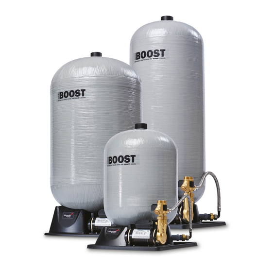
Please read instruction details carefully as they are intended to ensure this product provides long trouble free service. Failure to install the unit in accordance with the installation instructions will lead to invalidation of the warranty. 1. Product Description The AccuBoost unpumped range consists of a pressure vessel and integral base. The AccuBoost pumped range consists of a pressure vessel and an electrically operated pump attached to the integral base. -
Page 5: Pre-Installation Checklist
3. Pre-installation Checklist Our pre-installation guidelines are detailed on the following pages, but some of the key “do’s and don’ts” are highlighted below: Do’s Don’ts - Read this installation manual in full - Do not place any materials over the before commencing installation pump - Allow adequate ventilation of the pump... -
Page 6: Typical Combi Boiler Installations
4. Typical Combi Boiler Installations Unpumped Figure 1 Recommended upstream Maintenance Combi Outlets plumbing (not supplied) bypass Boiler (isolating valve Double Pressure Stop Inline not supplied) check reducing cock strainer valve valve Pumped Figure 2 Recommended upstream Maintenance Combi Outlets plumbing (not supplied) bypass Boiler... -
Page 7: Typical Unvented Cylinder Installations
5. Typical Unvented Cylinder Installations Unpumped Figure 3 Unvented Cylinder Recommended upstream Maintenance Outlets plumbing (not supplied) bypass (isolating valve Double Pressure Stop Inline not supplied) check reducing cock strainer valve valve Pumped Figure 4 Unvented Cylinder Recommended upstream Maintenance Outlets plumbing (not supplied) bypass... -
Page 8: Installation Instructions
6. Installation Instructions 6.1 Location All AccuBoost models are designed to be connected directly to the cold mains water supply within the property. Pumped models should ideally be connected directly after the stopcock. Unpumped AccuBoost units can be located within the building, loft areas, outbuildings, garages or basements - but the location must be dry and frost free. -
Page 9: Water Temperature
Loading/support: - The AccuBoost unit should be installed on a smooth, flat, level surface so that the pressure vessel is vertical. - The base of the unit should be fully supported across the entire base to ensure maximum stability and safe loading. Refer to Figure 5 - The floor/mounting surface must be able to withstand the maximum full weight of the AccuBoost unit (please refer to the technical specification for the weights of each unit). -
Page 10: Pipework
6.3 Pipework General plumbing: - Ensure pipework runs are as short as possible and minimise potential for airlocks. - To meet the requirements of the water supply (water fittings) regulations, a type EC- verifiable double check valve should be fitted. Refer to Figures 1-4 on page 4 & 5. - Ensure the combined mains pressure and pump pressure does not exceed the maximum system pressure of 8.6 Bar/860 kPa. - Page 11 - Unpumped units use the same pipework to the pressure vessel for both filling and emptying the vessel. This should be connected to the mains as shown in Figures 1 & 3. - Pumped units have a seperate inlet and outlet. Arrows on the brass end of the pump clearly show the inlet and outlet, refer to Figure 6.
-
Page 12: Air Precharge Pressure Of The Vessel
6.5 Air precharge pressure of the vessel To maintain optimum performance of the system, a pressure differential of approx. 1.5 Bar between the mains water static pressure and air precharge pressure within the vessel should be maintained. The air precharge of the vessel should never be less than 0.5 Bar. - Pumped units have the air precharge pressure set at the factory to 1.5 Bar/21.75PSI. - Page 13 Adjusting the air precharge pressure: - To reduce the air precharge pressure in the vessel, depress the centre of the Schrader valve to release air pressure. Only release a small amount of pressure at a time and then the remaining pressure should be checked again. Continue to do this until the correct air precharge pressure is achieved.
-
Page 14: Electrical Installation (Pumped Versions Only)
6.6 Electrical installation (pumped versions only) Your pump must be connected to the electrical supply using the supplied mains cable with the attached plug. This plug must be connected to an accessible socket that has been installed in compliance with IET Wiring Regulations. - The plug must be accessible at all times - If the supply cord is damaged, it must be replaced by the manufacturer, its service agent, or similarly qualified person in order to avoid a hazard. -
Page 15: Final Commissioning
7. Final Commissioning Priming (pumped versions only) It is critical to discharge water through the pump into a container using natural flow before connecting the outlet of the pump to the pipework. This ensures the air has been discharged from the inlet pipe work and pump chambers. The best method is :- - Connect the inlet pipework to the inlet anti-vibration hose - Check that all isolating valves on anti-vibration hoses are open - Turn on stopcock and allow water to flow from the pump outlet anti-vibration hose into a... -
Page 16: Accuboost Components
8. AccuBoost Components Unpumped example Figure 10 air precharge valve cover vessel base brass inlet/outlet connection front view side view Pumped example air precharge Figure 11 valve cover inlet outlet connection connection vessel vessel port pump base front view side view... -
Page 17: Maintenance
9. Maintenance Disconnect electrical supply before working on pump (on pumped versions). Turn off water supply to the unit, completely empty the vessel of water by opening outlets before attempting any maintenance. Cleaning the filters The inline strainer filter and filter washer (pumped units) should be cleaned at regular intervals to allow the free flow of water into the system. -
Page 18: Retro Fitting A Pump To An Unpumped Unit
If an unpumped unit has been installed and there is a requirement for a pumped version, a pump can be retrofitted (Salamander Pumps part code ACC-UPG-KIT), as long as all of the criteria within this manual are adhered to. IMPORTANT NOTE: ONLY A SALAMANDER PUMPS ACCUBOOST PUMP (ACC-UPG-KIT) CAN BE RETROFITTED - DO NOT ATTEMPT TO FIT ANY OTHER PUMP INCLUDING THOSE FROM THE OTHER SALAMANDER PUMPS RANGES. - Page 19 4. Attach the 4 anti vibration feet to the pump (one per corner). Place a pump retainer over 2 of the anti vibration feet. Repeat for the other side. Figure 15 5. Position the pump so that the retainer fixing holes line up with the holes on the vessel base.
-
Page 20: Multiple Vessels
11. Multiple Vessels If additional water storage capacity is required, multiple vessels can be installed in a system. NOTE: ONLY ONE PUMP CAN BE FITTED PER INSTALLATION. Additional vessels should be connected via a “T” on the vessel port of the pump (for pumped versions). A Salamander Pumps vessel connector kit (part code TNK-CON-KIT) can be purchased separately to allow multiple vessels to be connected. - Page 21 If multiple vessels are to be connected to a pumped AccuBoost unit, they should be connected after the outlet from the pump. It is advised to connect the vessels to the vessel port on the pump. To install multiple vessels to a pumped unit: 1.
-
Page 22: Technical Specification
12. Technical Specification Pumped Table 3 Part Number ACC-060-SYS ACC-120-SYS ACC-180-SYS ACC-300-SYS ACC-450-SYS Guarantee 3 years Maximum operating pressure 8.6 Bar/860 kPa Ambient temperature range 4°C to 49 °C Specification Vessel size (litres) Maximum vessel water storage 27.5 150.5 226.5 capacity (litres) Height (mm) 1126... -
Page 23: Weee Directive
Note: quoted values may vary due to tolerances and site conditions. Please Note: Salamander Pumps operates a policy of continuous development and reserves the right to change any of the specifications of it’s products without prior notice. All information, data and illustrations given in this leaflet may be subject to variation. -
Page 24: Troubleshooting
14. Troubleshooting Fault Probable cause Recommended solution Unpumped Valves not fully open Check all valves are fully open Reduced/poor flow Blocked filter Ensure all filters are free from debris Incoming mains pressure Check pressure of incoming mains. If below 2 Bar/200 kPa consider a dropped pumped version. -
Page 25: Warranty Information
Once the installation has been completed and the system has been tested to your satisfaction, please assist the customer in completing warranty registration. Please note that Salamander Pumps are able to provide an onsite service visit which may be chargeable. - Page 26 2 Terms and conditions This Warranty shall only be enforceable by you if the following terms and conditions have been complied with: a. That the equipment has been installed in accordance with the installation instructions, guidance and advice contained within the installation and warranty guide and/or provided by the Salamander help desk.
- Page 27 3 The Warranty periods The Warranty periods referred to in paragraph 1 above are as follows: a. i. AccuBoost Pumped products manufactured by the Company 3 years from date of purchase provided the warranty registration is completed online or over the phone within 15 days of purchase.
- Page 28 Get in touch, we’re here to help call us on 0191 516 2002 Unit 2c Colima Avenue Enterprise Park West Sunderland, SR5 3XE Register your warranty Apply online at: www.salamanderpumps.co.uk Apply by phone: 0191 516 2002...
Need help?
Do you have a question about the AccuBoost Series and is the answer not in the manual?
Questions and answers