
Related Manuals for Salamander Pumps TankBoost Series


Summary of Contents for Salamander Pumps TankBoost Series
- Page 1 Installation and warranty guide for TankBoost range This document should be given to the end user and retained for future reference. Should you need to contact Salamander Pumps you will need the below information.
-
Page 2: Table Of Contents
Regulations and local byelaws. Warranty Thank you for choosing Correct installation is the guarantee of safety Salamander Pumps Terms and Conditions and a trouble free system. It is therefore important to read these instructions thoroughly and ensure you comply with them. Incorrect fitting could cause serious injury, death, property damage and invalidate the warranty. -
Page 3: Product Description
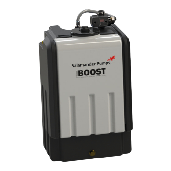
Product Description TankBoost Dimensions TankBoost is a single unit solution for TankBoost is available in 4 different tank TNK-200-SUB TNK-350-SUB TNK-450-SUB TNK-100-SUB domestic situations with low incoming mains sizes (100L, 200L 350L & 450L) depending water pressure or flow, and/or a restrictive on the volume of stored water required for incoming main water pipe (typically lead mains). -
Page 4: Installation Notes
Installation Notes Typical Installation Diagrams Outlet from TankBoost - Location Boosted water to outlets Outlet from TankBoost - and hot water system Boosted water to outlets - The floor/mounting surface (supporting - Ensure that the stored volume of water and hot water system TankBoost) must be flat and level, fully remains above 4°C and below 20°C to avoid Inlet to... -
Page 5: Electrical Installation
Electrical Installation Maintenance TankBoost must be connected to the If the supply cord is damaged, it must be Pressure Vessel Pre-Charge Regular Activation electrical supply using the mains cable, replaced by the manufacturer, its service - To maintain optimum performance of the - We recommend that the unit is activated for wired to a UK 3-pin plug or fused spur (with a agent, or similarly qualified person in order... -
Page 6: Technical Specification
Pressure sensor 4°C - 20°C Water Temperature Contact Salamander Pumps. outlets closed calibration The company operates a policy of continuous development and reserves the right to change any of the specifications of its products without prior notice. All information data and illustrations given in this leaflet may be subject to variation. -
Page 7: Control Unit Display Codes
Control Unit Display Codes Factory Reset (Control Unit) In normal operation the control unit Your unit is pre-set with its operating parameters during assembly and testing. displays pressure or current readings directly from the pump in the tank unit. If your unit is failing to operate and if instructed to do so by the Salamander Tech Desk team, An LED will be lit up to show whether please follow these instructions to reset your unit: the pressure is being displayed (in... -
Page 8: Additional Water Storage Tanks
Additional Water Storage Tanks WEEE Directive Your appliance contains valuable materials which WEEE Directive 2012/19/EU could be recovered or recycled. At the end of the Additional storage tanks must be the same size as the main pumped unit. At the end of the product life dispose product’s useful life please dispose of it at an All tanks must be located on the same level and as close together as possible so as of packaging and product in a... -
Page 9: Warranty
Warranty Terms and conditions This Warranty shall only be enforceable by you 1. The Scope of the Warranty 2. The Warranty Periods if the following terms and conditions have been SALAMANDER PUMPED SHOWER SYSTEMS The Warranty periods referred to in paragraph 1 complied with: LTD (“the company”) Warrants subject to the above are as follows:... - Page 11 Get in touch, we’re here to help call us on 0191 516 2002 Unit 2c Colima Avenue Enterprise Park West Sunderland, SR5 3XE For ROI/EU Customers: MT Agencies Ireland Ltd Fearn House, Jamestown Business Park Jamestown Road, Finglas Dublin 11, D11 K7TV Register your warranty Online at: www.salamanderpumps.co.uk...
Need help?
Do you have a question about the TankBoost Series and is the answer not in the manual?
Questions and answers