Table of Contents
Advertisement
Available languages
Available languages
Quick Links
Advertisement
Chapters
Table of Contents

Related Manuals for Stahl SolConeX 7570/11 Series


Summary of Contents for Stahl SolConeX 7570/11 Series
- Page 1 Betriebsanleitung Operating instructions Additional languages www.stahl-ex.com DE EN SolConeX Wandsteckdose, 16 A SolConeX Wall-Mounted Socket, 16 A Reihe 7570/11 Series 7570/11...
- Page 3 Betriebsanleitung Additional languages www.stahl-ex.com SolConeX Wandsteckdose, 16 A Reihe 7570/11...
-
Page 4: Table Of Contents
Inhaltsverzeichnis Allgemeine Angaben ...................3 Hersteller ......................3 Angaben zur Betriebsanleitung ................3 Weitere Dokumente ....................3 Konformität zu Normen und Bestimmungen ............3 Erläuterung der Symbole ..................3 Symbole in der Betriebsanleitung ...............3 Warnhinweise .....................4 Symbole am Gerät oder in Schaltplänen ............4 Sicherheitshinweise ....................5 Aufbewahrung der Betriebsanleitung ..............5 Sichere Verwendung ...................5 Umbauten und Änderungen ................5 Funktion und Geräteaufbau ................5... -
Page 5: De De
Diese ist rechtsverbindlich in allen juristischen Angelegenheiten. Weitere Dokumente • Datenblatt/Data sheet 7570 Weitere Sprachen, siehe www.stahl-ex.com. Konformität zu Normen und Bestimmungen Siehe Zertifikate und EG-Konformitätserklärung: www.stahl-ex.com. Erläuterung der Symbole Symbole in der Betriebsanleitung Symbol Bedeutung Tipps und Empfehlungen zum Gebrauch des Geräts Gefahr allgemein Gefahr durch explosionsfähige Atmosphäre... -
Page 6: 2.2 Warnhinweise
Erläuterung der Symbole Warnhinweise Warnhinweise unbedingt befolgen, um das konstruktive und durch den Betrieb bedingte Risiko zu minimieren. Die Warnhinweise sind wie folgt aufgebaut: • Signalwort: GEFAHR, WARNUNG, VORSICHT, HINWEIS • Art und Quelle der Gefahr/des Schadens • Folgen der Gefahr •... -
Page 7: Sicherheitshinweise
Bemessungsbetriebsbedingungen) auf Typ- und Datenschildern sowie die Hinweisschilder am Gerät mit den Kabel- und Leitungseinführungen beachten. • Bei Betriebsbedingungen, die von den technischen Daten abweichen, unbedingt bei der R. STAHL Schaltgeräte GmbH rückfragen. Umbauten und Änderungen WARNUNG Gefahr durch Umbauten und Änderungen am Gerät! Explosionsschutz gefährdet! -
Page 8: 5 Technische Daten
Technische Daten Technische Daten Explosionsschutz Europa (ATEX) Gas und Staub PTB 05 ATEX 1013 E II 3 G Ex nA nC [ia Ga] IIC T6 Gc E II 3 D Ex tc IIIC T80°C Dc Bescheinigungen und Zertifikate Bescheinigungen ATEX Technische Daten Elektrische Daten Bemessungs-... -
Page 9: 6 Transport Und Lagerung
2 x M 25 x 1,5; wahlweise auch Verschlussstopfen oder metallische Einführungen Verschlussstopfen 1 x M25 x 1,5 Weitere technische Daten, siehe www.stahl-ex.com. Transport und Lagerung • Gerät nur in Originalverpackung transportieren und lagern. • Gerät trocken (keine Betauung) und erschütterungsfrei lagern. -
Page 10: Montage Und Installation
Montage und Installation Montage und Installation Maßangaben / Befestigungsmaße Maßzeichnung (alle Maße in mm [Zoll]) – Änderungen vorbehalten 10338E00 10333E00 7570/11-3.. 7570/11-4.. und 7570/11-5.. Anordnung der Schutzkontaktbuchse Position: Uhrzeit-Stellung, Ansicht: Vorderseite der Steckdose Beispiel: Uhrzeit-Stellung 06190E00 250 V = 6 h 02395E00 Anordnung der Kontaktbuchsen und Klemmenbezeichnungen 2 P + ¿... - Page 11 Montage und Installation Kennfarbe und Anordnung der Kontaktbuchsen und Klemmenbezeichnungen Polzahl* Frequenz Spannung Kennfarbe Lage der [Hz] Schutzkontaktbuchse 7570/11-3.. 50 und 60 100 ... 130 gelb 2 P + ¿ 50 und 60 200 ... 250 blau hellgrau 50 und 60 480 ...
-
Page 12: Montage / Demontage, Gebrauchslage
Montage und Installation Montage / Demontage, Gebrauchslage 7.2.1 Montage Bei freier Witterung das Gehäuse mit Schutzdach oder -wand ausrüsten. Gebrauchslage Klappdeckel nach unten, Anschlussraum nach oben. • Wandsteckdose mit vier Schrauben in senkrechter Gebrauchslage an einer ebenen Wand befestigen. Die Befestigungsbohrungen sind als Langlöcher ausgebildet. Dadurch ist ein vertikaler und horizontaler Montageausgleich möglich. -
Page 13: Installation
Montage und Installation Installation WARNUNG Gefahr durch spannungsführende Teile! Schwerste Verletzungen möglich! • Alle Anschlüsse und Verdrahtungen spannungsfrei schalten. • Anschlüsse gegen unbefugtes Schalten sichern. GEFAHR Explosionsgefahr! Verletzungen und Sachschäden drohen! • Durch geeignete Leiterauswahl sicherstellen, dass maximal zulässige Leitertemperaturen nicht überschritten werden. •... - Page 14 Montage und Installation Abmessungen [mm] Hauptkontakte Hilfskontakte Hilfskontakte Ex i • Gehäuse öffnen. • Kabel durch Kabeleinführung in Anschlussraum führen. • Leitungen in entsprechende Klemmen einführen und festklemmen (Anzugsdrehmoment siehe Kapitel „Technische Daten“). Die abisolierten Leitungsenden müssen sich vollständig unter der Klemmplatte befinden.
-
Page 15: Betrieb
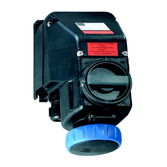
Die Wandsteckdose darf nur in komplett montiertem Zustand betrieben werden. Die Wandsteckdose ist nur bei eingestecktem Stecker schaltbar. Bei gezogenem Stecker Klappdeckel mit dem Bajonettring verschließen. Es dürfen ausschließlich Stecker vom Typ 7570/12 und 8570/12 der Fa. R. STAHL verwendet werden. 126407 / 7570601300 SolConeX Wandsteckdose, 16 A 2014-01-21·BA00·III·de·01... -
Page 16: Instandhaltung, Wartung, Reparatur
Instandhaltung, Wartung, Reparatur Instandhaltung, Wartung, Reparatur WARNUNG Unbefugte Arbeiten am Gerät! Gefahr von Verletzungen und Sachschäden! • Arbeiten am Gerät ausschließlich von dazu befugtem und entsprechend geschultem Personal ausführen lassen. 10.1 Instandhaltung • Art und Umfang der Prüfungen den entsprechenden nationalen Vorschriften entnehmen. -
Page 17: 10.3 Reparatur
10.3 Reparatur GEFAHR Gefahr durch unsachgemäße Wartung/Reparatur! Explosionsschutz gefährdet! • Reparaturen am Gerät nur von R. STAHL Schaltgeräte GmbH durchführen lassen. 10.4 Rücksendung Für die Rücksendung im Reparatur-/Servicefall das Formular "Serviceschein" verwenden. Auf der Internetseite "www.stahl-ex.com" im Menü "Downloads >... - Page 18 SolConeX Wandsteckdose, 16 A 126407 / 7570601300 Reihe 7570/11 2014-01-21·BA00·III·de·01...
- Page 19 Operating instructions Additional languages www.stahl-ex.com SolConeX Wall-Mounted Socket, 16 A Series 7570/11...
- Page 20 Contents General Information ....................3 Manufacturer .......................3 Information Regarding the Operating Instructions ..........3 Further Documents .....................3 Conformity with Standards and Regulations ............3 Explanation of the Symbols ................3 Symbols in these Operating Instructions ............3 Warning Notes ....................4 Symbols on the Device or in the Circuit Diagrams ..........4 Safety Notes .......................5 Operating Instructions Storage ................5 Safe Use ......................5...
-
Page 21: En En
They are legally binding in all legal affairs. Further Documents • Data sheet 7570 For further languages, see www.stahl-ex.com. Conformity with Standards and Regulations See certificates and EC Declaration of Conformity: www.stahl-ex.com. Explanation of the Symbols Symbols in these Operating Instructions Symbol Meaning... -
Page 22: 2.2 Warning Notes
Explanation of the Symbols Warning Notes Warning notes must be observed under all circumstances, in order to minimize the risk due to construction and operation. The warning notes have the following structure: • Signalling word: DANGER, WARNING, CAUTION, NOTICE • Type and source of danger/damage •... -
Page 23: Safety Notes
• Always consult with R. STAHL Schaltgeräte in case of operating conditions which deviate from the technical data. Modifications and Alterations... -
Page 24: 5 Technical Data
Technical Data Technical Data Explosion protection Europe (ATEX) Gas and dust PTB 05 ATEX 1013 E II 3 G Ex nA nC [ia Ga] IIC T6 Gc E II 3 D Ex tc IIIC T80°C Dc Certifications and certificates Certificates ATEX Technical data Electrical data... -
Page 25: 6 Transport And Storage
Stopping plug 1 x M25 x 1.5 For further technical data, see www.stahl-ex.com. Transport and Storage • Transport and store the device only in the original packaging. • Store the device in a dry place (no condensation) and vibration-free. -
Page 26: Mounting And Installation
Mounting and Installation Mounting and Installation Dimensions / Fastening Dimensions Dimensional drawings (all dimensions in mm [inch]) – Subject to alterations 10338E00 10333E00 7570/11-3.. 7570/11-4.. and 7570/11-5.. Arrangement of the earth contact sleeve Position: clock hour position, View: front side of the socket Example: clock hour position 06190E00 250 V = 6 h... - Page 27 Mounting and Installation Colour code and arrangement of socket contacts and terminal markings No. of poles* Frequency Voltage Colour code Position of earth [Hz] contact sleeve 7570/11-3.. 50 and 60 100 ... 130 yellow 2 P + ¿ 50 and 60 200 ...
-
Page 28: Mounting / Dismounting, Operating Position
Mounting and Installation Mounting / Dismounting, Operating Position 7.2.1 Assembly Install a protective roof or wall if mounted outdoors. Operating position Hinged cover at the bottom, connection chamber on top. • Fasten the wall-mounting socket using four screws in the vertical operating position to a flat wall. -
Page 29: Installation
Mounting and Installation Installation WARNING Danger due to live components! Risk of severe injuries! • Disconnect all connectors and wires from the power supply. • Secure the connections against unauthorized switching. DANGER Risk of explosion! Risk of injuries and material damage! •... - Page 30 Mounting and Installation Dimensions [mm] Main contacts Auxiliary contacts Ex i auxiliary contacts • Open the enclosure. • Lead the cable through the cable gland into the connection chamber. • Insert the conductors in the corresponding terminals and clamp them (for tightening torque refer to section "Technical Data").
-
Page 31: Operation
The wall-mounting socket can be switched only with the plug inserted. When the plug has been disconnected, close the hinged cover with the bayonet ring. Only type 7570/12 and 8570/12 plugs by R. STAHL may be used. 126407 / 7570601300 SolConeX Wall-Mounted Socket, 16 A 2014-01-21·BA00·III·en·01... -
Page 32: Maintenance And Repair
Maintenance and Repair Maintenance and Repair WARNING Unauthorized work being performed on the device! Risk of injuries and material damage! • Work performed on the device must only be carried out by appropriately authorized and trained personnel. 10.1 Maintenance • Consult the relevant national regulations to determine the type and extent of inspections. -
Page 33: 10.3 Repair
• Ensure environmentally friendly disposal of all components according to the statutory regulations. Accessories and Spare Parts NOTICE Use only original accessories and spare parts by R. STAHL Schaltgeräte GmbH. For accessories and spare parts, see data sheet on our homepage www.stahl-ex.com. 126407 / 7570601300 SolConeX Wall-Mounted Socket, 16 A 2014-01-21·BA00·III·en·01... - Page 34 SolConeX Wall-Mounted Socket, 16 A 126407 / 7570601300 Series 7570/11 2014-01-21·BA00·III·en·01...
- Page 36 126407 / 7570601300 2014-01-21·BA00·III·de/en·01...
Need help?
Do you have a question about the SolConeX 7570/11 Series and is the answer not in the manual?
Questions and answers