
Related Manuals for Stahl 8575/13


Summary of Contents for Stahl 8575/13
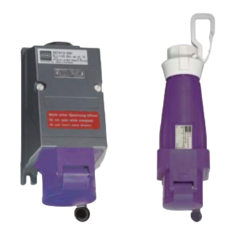
- Page 1 Betriebsanleitung/Operating instructions Wandsteckdose/ Kupplungsdose Wall-mounting socket/ Coupler > 8575/13 > 8575/14...
- Page 3 Betriebsanleitung Wandsteckdose/ Kupplungsdose > 8575/13 > 8575/14...
-
Page 4: Table Of Contents
Inbetriebnahme .....................8 Reparatur und Instandhaltung ................8 Zubehör und Ersatzteile ..................9 Entsorgung ......................9 Baumuster-Prüfbescheinigung (1. Seite) ............10 Konformitätserklärung ..................11 Allgemeine Angaben 2.1 Hersteller R. STAHL Schaltgeräte GmbH Am Bahnhof 30 D-74638 Waldenburg Telefon: +49 7942 943-0 Telefax: +49 7942 943-4333 Internet: www.stahl.de... -
Page 5: Sicherheitshinweise
Die Geräte dürfen nur in geschlossenem Zustand mit aufgesetztem Anschlussraum- deckel betrieben werden! Vor Öffnen des Gerätes Spannungsversorgung unterbrechen! Die Wandsteckdose Typ 8575/13 und die Kupplungsdose Typ 8575/14 sind nur bei eingestecktem Stecker einschaltbar. Es dürfen nur Stecker vom Typ 8575/12 der Fa. R. Stahl verwendet werden. -
Page 6: Funktion
Funktion Funktion Die Wandsteckdose Typ 8575/13 und die Kupplungsdose Typ 8575/14 sind explosions- geschützte elektrische Betriebsmittel. Sie dienen zum Anschluss ortsveränderlicher und ortsfester elektrischer Betriebsmittel sowie zur Verbindung von Leitungen bzw. Stromkreisen in explosionsgefährdeten Bereichen. Technische Daten Explosionsschutz E II 2 G EEx ed IIC T* Gasexplosionsschutz ( 45 °C... - Page 7 12 h 12 h hellgrau 20 - 25 und 40 - 50 100 - 200 grün > 400 - 500 11 h 11 h 20 - 25 10 h violett 40 - 50 10 h hellgrau 8575618300 Wandsteckdose/Kupplungsdose S-BA-8575/13/14-01-de-11/04/2007 8575/13/8575/14...
-
Page 8: Montage
Klappdeckel nach unten, Anschlussraum nach oben Hängende Befestigung mit der Halteöse Die Wandsteckdose Typ 8575/13 ist mittels vier Schrauben in senkrechter Gebrauchslage an ebener Wand zu befestigen (Befestigungsmaße siehe Maßskizze oder Geräterückseite). Die Befestigungsbohrungen sind als Langlöcher ausgebildet, dadurch ist ein vertikaler und horizontaler Montageausgleich möglich. - Page 9 Installation Leitungsanschluss Wandsteckdose 8575/13: Anschlussraumdeckel öffnen. Leitung durch die Leitungseinführung in den Anschlussraum schieben. Leitung (max. 4 mm ) abisolieren. 09197T00 Abisolierte Leitungsenden an den entsprechenden Klemmstellen am Steckdosen- flansch unterklemmen. Beim Unterklemmen ist darauf zu achten, dass sich die abisolierten Leitungsenden vollständig unter der Klemmplatte befinden.
-
Page 10: Inbetriebnahme
Das Eindringen von Reinigungsmitteln und Wasser in die Kontaktbuchsen ist zu vermeiden. WARNUNG Nach jedem im Hauptstromkreis des Schalters aufgetretenen Kurzschluss muss der Schalter ausgetauscht werden, da bei einem hermetisch abgeschlossenen Betriebsmittel der Zustand der Schaltkontakte nicht überprüft werden kann. Wandsteckdose/Kupplungsdose 8575618300 8575/13/8575/14 S-BA-8575/13/14-01-de-11/04/2007... -
Page 11: Zubehör Und Ersatzteile
Zubehör und Ersatzteile 11 Zubehör und Ersatzteile WARNUNG Verwenden Sie nur Original-Zubehör sowie Original-Ersatzteile der Fa. R. STAHL Schaltgeräte GmbH. Benennung Beschreibung Bestellnummer Gewicht Steckdosenflansch für 8575/1.-100, 2-polig 8575069490 0,360 für 8575/1.-110, 2-polig 8575070490 0,362 für 8575/1.-112, 2-polig 8575071490 0,364 für 8575/1.-200, 3-polig... - Page 12 Operating Instructions Wall-mounting socket/ Coupler > 8575/13 > 8575/14...
- Page 13 Repairs and Maintenance ..................8 Accessories and spare parts .................9 Disposal .........................9 Type examination certificate (Page 1) ..............10 Declaration of conformity ..................11 General Information 2.1 Manufacturer R. STAHL Schaltgeräte GmbH Am Bahnhof 30 D-74638 Waldenburg Telephone: +49 7942 943-0 Fax: +49 7942 943-4333 Internet: www.stahl.de...
-
Page 14: Safety Instructions
Sockets may only be used fully closed with connection area cover in place! Before opening the socket, disconnect it from the supply! Wall-mounting socket 8575/13 and coupler 8575/14 can only be energised if a plug is inserted. Only type 8575/12 plugs from R. STAHL may be used. -
Page 15: Function
Function Function The wall-mounting socket type 8575/13 and the coupler type 8575/14 are explosion- protected electrical devices which connect portable and fixed electrical equipment as well as cables and circuits in hazardous areas. Technical Data Explosion protection E II 2 G EEx ed IIC T* Gas explosion protection ( 45 °C... - Page 16 100 - 200 4 o’clock 4 o’clock green 2 o’clock 2 o’clock 3 o’clock 3 o’clock > 400 - 500 11 o’clock 11 o’clock 20 - 25 10 o’clock violet 40 - 50 10 o’clock light grey 8575618300 Wall-mounting socket/Coupler S-BA-8575/13/14-01-en-11/04/2007 8575/13/8575/14...
-
Page 17: Mounting
Flap cover facing downwards, connection area at the top Suspended by clip ring The type 8575/13 wall-mounting socket must be fixed vertically with four screws on a flat wall. (For fixing dimensions, see sketch above or back of socket itself.) The fixing holes are elongated. - Page 18 Installation Connections for wall-mounting socket 8575/13: Open connection area cover. Push cable through cable gland and into connection area. Remove insulation from cable (max. 4 mm ) ends. 09197T00 Fit stripped cable ends to appropriate terminal slots in socket flange and tighten clamp.
-
Page 19: Commissioning
To avoid corrosion, do not allow cleaning fluids and water to penetrate the socket body. WARNING The contact element must be replaced after each short-circuit in the switch main circuit. This is because the element is hermetically sealed and the state of the switching contacts cannot be checked. Wall-mounting socket/Coupler 8575618300 8575/13/8575/14 S-BA-8575/13/14-01-en-11/04/2007... -
Page 20: Accessories And Spare Parts
Accessories and spare parts 11 Accessories and spare parts WARNING Use only original spare parts as well as original accessories made by R. STAHL Schaltgeräte GmbH. Designation Description Ordering code Weight Socket flange for 8575/1.-100, 2-pole 8575069490 0,360 for 8575/1.-110, 2-pole...
Need help?
Do you have a question about the 8575/13 and is the answer not in the manual?
Questions and answers