
Subscribe to Our Youtube Channel
Related Manuals for Stahl 7571/11 Series


Summary of Contents for Stahl 7571/11 Series
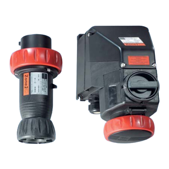
- Page 1 Typen / Types 7571/11, 7571/12 Wandsteckdose, Stecker Wall-mounting socket, Plug Prise murale, Fiche BETRIEBSANLEITUNG OPERATING INSTRUCTIONS INSTRUCTIONS DE SERVICE...
-
Page 2: Table Of Contents
INHALT Symbole ..........................1 Sicherheitshinweise ......................1 Normenkonformität ......................2 Funktion..........................2 Technische Daten ......................2 Anordnung und Montage ....................6 Installation .........................8 Inbetriebnahme / Betrieb ....................11 Instandhaltung .........................12 Transport und Lagerung....................13 Entsorgung ........................13 CONTENTS Symbols ...........................15 Safety instructions ......................15 Conformity to standards ....................16 Function..........................16 Technical data .........................16 Arrangement and Fitting ....................20 Installation ........................22... -
Page 3: Symbole
Symbole Symbole Achtung! Diese Grafik kennzeichnet Hinweise, bei deren Nichtbeachtung Ihre Gesundheit oder die Funktionsfähigkeit des Gerätes bzw. der Komponente gefährdet ist. Hinweis Diese Grafik kennzeichnet wichtige Zusatzinformationen, Tipps und Empfehlungen. Sicherheitshinweise In diesem Kapitel sind die wichtigsten Sicherheitsmaßnahmen zusammengefasst. Es ergänzt die entsprechenden Vorschriften, zu deren Studium das verantwortliche Perso- nal verpflichtet ist. -
Page 4: Normenkonformität
Normenkonformität Normenkonformität Die Geräte entsprechen den folgenden Normen bzw. der folgenden Richtlinie: • Richtlinie 94/9/EG • EN 50 014, EN 50 018, EN 50 019, EN 50 020, EN 50 281-1-1 • IEC 60 079-1, IEC 60 079-7, IEC 60 079-11, IEC 61 241-1 •... - Page 5 Technische Daten 5.2 Mechanische Daten Material Polyamid GF30 Gewicht 7571/11-4 2,0 kg 7571/11-5 2,2 kg 7571/12-4 0,5 kg 7571/12-5 0,6 kg Lebensdauer 5000 Schaltzyklen (elektrisch und mechanisch) Anzugsdrehmomente Klemmen: max. 1,6 Nm Anschlussraum- deckel der Wandsteckdose: max. 1,8 Nm Steckergehäuse: max.
- Page 6 Technische Daten Schaltleistung gemäß IEC 60 947 690 V 32 A Hilfskontakte: AC15 500 V max. 1250 VA AC15 230 V max. 1380 VA AC12 500 V max. 3000 VA DC13 110 V max. 110 W Leistung 7,5 kW 220/230/240 V 15 kW 380/400/415 V 30 kW...
- Page 7 Technische Daten 5.3.2 Kennfarbe und Anordnung der Schutzkontaktbuchse Polzahl Frequenz Bemessungsbetriebs- Kennfarbe Lage der spannung Schutzkontakt- [Hz] buchse 50-60 200-250 blau 380-415 7571/..-4.. 440-460 1) rot 11 h 50-60 480-500 schwarz 600-690 schwarz 100-300 2) > 50 grün 10 h 50-60 120/208-144/250 blau...
-
Page 8: Anordnung Und Montage
Anordnung und Montage Anordnung und Montage 6.1 Maßzeichnungen Abbildung 6-1: Maßzeichnung Typ 7571/11-4.. und Typ 7571/11-5.. Abbildung 6-2: Maßzeichnung Typ 7571/12-506 Ausführungen Abmessungen [mm] 7571/12-4.. (32 A, 3P+ 63,4 7571/12-5.. (32 A, 3P+N+ Tabelle 6-1: Verschiedene Ausführungen des Steckers Typ 7571/12-... Wandsteckdose Typ 7571/11 und Stecker Typ 7571/12... - Page 9 Anordnung und Montage 6.2 Montage Bei freier Bewitterung wird empfohlen, das Gehäuse mit Schutzdach oder -wand auszu- rüsten. Zum Schutz gegen Verschmutzung der Steckerstifte kann eine passende Schutzkappe verwendet werden (Bestell-Nr. siehe Zubehör). Montage Typ 7571/11 Gebrauchslage: Klappdeckel nach unten, Anschlussraum nach oben. •...
-
Page 10: Installation
Installation Installation Beachten Sie bei der Installation die nationalen Normen sowie die anerkannten Regeln der Technik (ebenso die Angaben zu den Klemmen innerhalb der Technischen Daten). Schalten Sie vor dem Öffnen des Gerätes die Spannung ab! 7.1 Netzanschluss Stellen Sie durch geeignete Auswahl der verwendeten Leitungen sowie durch die Art der Verlegung sicher, dass maximal zulässige Leitertemperaturen nicht überschritten werden. - Page 11 Installation Leitungsanschluss Wandsteckdose 7571/11 Abmessungen [mm] Hauptkontakte Hilfskontakte Hilfskontakte EEx i Tabelle 7-1: Maße Leitungsisolation • Öffnen Sie den Anschlussraumdeckel. • Schieben Sie die Leitung durch die Leitungseinführung in den Anschlussraum. • Isolieren Sie die Leitung ab. • Klemmen Sie die abisolierten Leitungsenden an den entsprechenden Klemmstellen. ACHTUNG: Die abisolierten Leitungsenden müssen sich vollständig unter der Klemmplatte befinden! •...
- Page 12 Installation • Schieben Sie die Leitung (max. 10 mm²) durch Verschraubung (3), Druckring (5), Dichtung (6) und das Steckergehäuse (2). Passen Sie die Innendurchmesser der Dichtung (6) gegebenenfalls durch ausschneiden an die Leitung an. • Schwenken Sie die Zugentlastung (7) am Steckerkragen um 90° ab. •...
-
Page 13: Inbetriebnahme / Betrieb
Typ 7571/11 Die Wandsteckdose Typ 7571/11 ist nur bei eingestecktem Stecker einschaltbar. Es dürfen nur Stecker vom Typ 7571/12, 8571/12, 7578/12 und 8578/12 der Fa. R. STAHL verwendet werden. Achten Sie bei gezogenem Stecker darauf, dass der Klappdeckel der Steckdose mit dem Bajonettring verschlossen ist. -
Page 14: Instandhaltung
Instandhaltung Instandhaltung 9.1 Wartung Wartungs-, Reparatur-, und Instandsetzungsarbeiten an den Geräten dürfen nur von dazu befugtem und entsprechend geschultem Personal durchgeführt werden. Beachten Sie auch die geltenden nationalen Bestimmungen im Einsatzland! Schalten Sie vor Beginn der Wartungsarbeiten die Geräte spannungsfrei! Ziehen Sie die Stecker in regelmäßigen Abständen um Kontaktkorrosion vorzubeugen! Überprüfen Sie im Rahmen der Wartung •... -
Page 15: Transport Und Lagerung
Transport und Lagerung 9.3 Zubehör und Ersatzteile Verwenden Sie nur Original-Zubehör sowie Original-Ersatzteile der Firma R. STAHL Schaltgeräte GmbH. Bei Verwendung von Zubehör und Ersatzteilen von Fremdherstel- lern erlischt die Garantie der Firma R. STAHL Schaltgeräte GmbH. Benennung für Typ... - Page 16 Entsorgung Wandsteckdose Typ 7571/11 und Stecker Typ 7571/12...
-
Page 17: Symbols
Symbols Symbols Warning! This symbol indicates advice which, if ignored, puts your health or the ability of the de- vice or devices to function at risk. Note This symbol indicates important additional information, tips and recommendations. Safety instructions The most important safety instructions are summarised in this chapter. It is intended to supplement the relevant regulations which must be studied by the personnel responsi- ble. -
Page 18: Conformity To Standards
Conformity to standards Conformity to standards The devices comply with the following standards and directives: • Directive 94/9/EC • EN 50 014, EN 50 018, EN 50 019, EN 50 020, EN 50 281-1-1 • IEC 60 079-1, IEC 60 079-7, IEC 60 079-11, IEC 61 241-1 •... - Page 19 Technical data 5.2 Mechanical data Material Polyamide GF30 Weight 7571/11-4 2,0 kg 7571/11-5 2,2 kg 7571/12-4 0,5 kg 7571/12-5 0,6 kg Service life 5000 switching cycles (electrical and mechanical) Tightening torques Terminals: max. 1.6 Nm Terminal chamber cover of wall-mount. socket: max.
- Page 20 Technical data Switching capacity as per 690 V 32 A IEC 60 947 Auxiliary contacts: AC15 500 V max. 1250 VA AC15 230 V max. 1380 VA AC12 500 V max. 3000 VA DC13 110 V max. 110 W Power 7.5 kW 220/230/240 V 15 kW...
- Page 21 Technical data 5.3.2 Colour coding and earthing contact socket configuration Number of Frequency Rated operating Identification Position of the pins voltage colour earthing [Hz] contact socket 50-60 200-250 blue 9 o’clock 380-415 6 o’clock 7571/..-4.. 440-460 1) red 11 o’clock 50-60 480-500 black...
-
Page 22: Arrangement And Fitting
Arrangement and fitting Arrangement and fitting 6.1 Dimension drawings Figure 6-1: Dimension drawing for Type 7571/11-4.. and Type 7571/11-5.. Figure 6-2: Dimension drawing for Type 7571/12-506 Versions Dimensions [mm] 7571/12-4.. (32 A, 3P+ 63.4 7571/12-5.. (32 A, 3P+N+ Table 6-1: Various versions of plug Type 7571/12-... Wall-mounting socket Type 7571/11 and plug Type 7571/12... - Page 23 Arrangement and fitting 6.2 Fitting If deployed outdoors / where exposure to the elements is the case, it is recommended to fit the enclosure with a protective roof or wall. To prevent contamination of the plug pins, a fitted protective cap can be used (Order No. see Accessories).
-
Page 24: Installation
Installation Installation During installation, adhere to the national standards as well as the generally recognised technical regulations (in addition to information pertaining to the terminals contained in the technical data). Disconnect the power supply before opening the device! 7.1 Mains connection Ensure that the maximum permissible conductor temperatures are not exceeded by se- lecting suitable cables and a suitable means of running them. - Page 25 Installation Lead connection for wall-mounting socket 7571/11 Dimensions [mm] Main operating contacts Auxiliary contacts EEx i auxiliary contacts Table 7-1: Dimensions for stripping leads • Open the terminal chamber cover. • Guide the lead through the cable entry and into the terminal chamber. •...
- Page 26 Installation • Guide the lead (max. 10 mm²) through the gland nut (3), thrust ring (5), gasket (6) and the plug enclosure (2). If necessary, adjust the inner diameter of the gasket (6) by cutting it to accommodate the lead diameter. •...
-
Page 27: Commissioning / Operation
Wall-mounting socket Type 7571/11 is only supplied with power when a plug is inserted. It should only be used in conjunction with Type 7571/12, 8571/12, 7578/12 or 8578/12 plugs from R.STAHL. Make sure that the socket’s hinged cover is closed with the bayonet ring when the plug is pulled out. Type 7571/12 The plug may only be placed in operation when it is completely and appropriately installed! After a short circuit, thoroughly check the functionality of the plug. -
Page 28: Servicing
Servicing Servicing 9.1 Maintenance Maintenance, repair and servicing work on the devices must only be performed by person- nel who are both authorised and suitably trained for this purpose. Observe the relevant national regulations in the country of use! Before any maintenance work commences, the devices must be disconnected from the power supply! To prevent contact corrosion, pull out the plug from the socket at regular intervals. -
Page 29: Transport And Storage
Transportation and storage 9.3 Accessories and spare parts Use only original accessories and spare parts from R. STAHL Schaltgeräte GmbH. Use of another company's accessories and spare parts invalidates the warranty of R. STAHL Schaltgeräte GmbH. Designation for Type Ordering code... - Page 30 Disposal Wall-mounting socket Type 7571/11 and plug Type 7571/12...
-
Page 31: Symboles
Symboles Symboles Attention ! Ce symbole caractérise les remarques, dont la non-observation met en danger votre santé ou le fonctionnement de l'appareil ou des composants. Remarque Ce symbole caractérise des informations complémentaires, conseils et recommanda- tions d'importance. Consignes de sécurité Dans ce chapitre sont résumées les mesures de sécurité... -
Page 32: Conformité Aux Normes
Conformité aux normes reils et composants, susceptibles d'entraver la protection antidéflagrante, ne sont pas autorisées. Les appareils et composants ne doivent être montés que dans un état intact, sec et propre. Conformité aux normes Les appareils sont conformes aux normes et directives suivantes : •... - Page 33 Caractéristiques techniques Poids 7571/11-4 2,2 kg 7571/11-5 2,0 kg 7571/12-4 0,5 kg 7571/12-5 0,6 kg Durée de vie 5000 cycles de connexion (mécanique et électrique) Couples de serrage Bornes de connexion : maxi 1,6 Nm Couvercle d’entrée des raccordements de la prise murale : 1,8 Nm maxi Boîtier de la fiche : 1,0 Nm maxi...
- Page 34 Caractéristiques techniques Puissance 7,5 kW 220/230/240 V 15 kW 380/400/415 V 30 kW 600/690 V puissance de base 35 A maxi (sans protection thermique) Fusible de puissance puissance de base 63 A maxi (avec protection thermique) Type de raccordement Type 7571/11 : 2 x 2,5 ...
- Page 35 Caractéristiques techniques 5.3.2 Couleur d’identification et disposition de la douille de sécurité Nombre Fréquence Tension d’utilisation Couleur Position de la de pôles assignée d’identification douille de [Hz] sécurité 50-60 200-250 bleu 380-415 rouge 7571/..-4.. 440-460 1) rouge 11 h 50-60 480-500 noir 600-690...
-
Page 36: Disposition Et Montage
Disposition et montage Disposition et montage 6.1 Plans d’encombremen Figure 6-1: Plan d’encombrement type 7571/11-4.. et type 7571/11-5.. Figure 6-2: Plan d’encombrement type 7571/12-506 Versions Dimensions [mm] 7571/12-4.. (32 A, 3P+ 63,4 7571/12-5.. (32 A, 3P+N+ Tableau 6-1 Différentes versions de la fiche type 7571/12-... Prise murale type 7571/11 et connecteur type 7571/12... - Page 37 Disposition et montage 6.2 Montage En cas de libre exposition aux agents atmosphériques, il faut équiper le boîtier d’un pro- tège-conducteur ou d’une paroi de protection. Pour protéger les fiches mâles contre l’encrassement, on peut utiliser un capuchon adap- té (pour le n° de pièce voir dans accessoires). Montage type 7571/11 Position d’utilisation : Couvercle rabattant vers le bas, zone d’entrée des raccordements vers le haut.
-
Page 38: Installation
Installation Installation Respectez lors de l’installation les normes nationales ainsi que les règles de l’art de la technique (et les indications relatives aux bornes dans les caractéristiques techniques). Avant l’ouverture de l’appareil, coupez la tension ! 7.1 Raccordement secteur Pour ne pas dépasser la température maximale autorisée, il convient de bien choisir les conducteurs ainsi que leur cheminement. - Page 39 Installation Raccordement de conducteurs prise murale type 7571/11 Dimensions [mm] Contacts principaux Contacts auxiliaires Contacts auxiliaires EEX i Tableau 7-1 Dimensions du dénudage des conducteurs • Ouvrez le couvercle du logement des raccordements. • Insérez le conducteur à travers l’entrée de conducteur dans le logement des raccor- dements.
- Page 40 Installation • Passez le conducteur (10 mm² maxi) à travers le raccord à vis (3), le cône de ser- rage (5), le joint d’étanchéité (6) et le boîtier de la fiche (2). Adaptez le diamètre inté- rieur du joint d’étanchéité (6) au conducteur par découpe si besoin. •...
-
Page 41: Mise En Service / Fonctionnement
La fiche ne peut être utilisée que dans un état complètement monté ! Après un court-circuit dans le circuit électrique, vérifier le fonctionnement de la fiche. La fiche type 7571/12 peut être utilisée avec les produits suivant de la société R. STAHL Schaltgeräte GmbH : •... -
Page 42: Maintenance
Maintenance Maintenance 9.1 Entretien Les travaux de maintenance, de réparation et d’entretien sur les appareils doivent unique- ment être effectués par des personnes autorisées et formées à cet effet. Observez éga- lement les réglementations en vigueur dans le pays d'utilisation ! Avant toute intervention, les appareils doivent être mis hors tension ! Retirez les fiches à... -
Page 43: Transport Et Stockage
Transport et stockage 9.3 Accessoires et pièces de rechange Utilisez uniquement des pièces de rechange et des accessoires d'origine de R. STAHL Schaltgeräte GmbH. L'utilisation d'accessoires et de pièces de rechange d'autres cons- tructeurs annule la garantie de R. STAHL Schaltgeräte GmbH. - Page 44 Réglementation concernant les déchets Prise murale type 7571/11 et connecteur type 7571/12...
-
Page 45: Anhang / Appendix / Annexes
Anhang / Appendix / Annexes Typen / Types 8571/11, 8571/12... - Page 47 Si vous avez besoin des instructions de mise en service dans une autre langue de l'Union Euro- péenne, prière de contacter votre Représentant R. STAHL. En caso necesario podrá solicitar de su representante R. STAHL estas instrucciones de servicio en otro idioma de la Union Europea.
- Page 48 R. STAHL Schaltgeräte GmbH Am Bahnhof 30 74638 Waldenburg (Württ.) 75 716 01 30 0 S-BA-7571-00-de/en/fr-04/2005 www.stahl.de...
Need help?
Do you have a question about the 7571/11 Series and is the answer not in the manual?
Questions and answers